

Page 1

Contents
Conveyor module XTUC S11 ........................................................................ 3
Conveyor module XTUC S51 ........................................................................ 4
Conveyor module XTUC J51/J52.................................................................. 4
Conveyor module XTUC L51/L52.................................................................. 4
Conveyor module XTUC U51/U52................................................. ... ............. 4
Conveyor module XTUC Z51/Z52 ................................................................. 4
Conveyor module XTUC F51/F52 ................................................................. 4
Conveyor module XTUC Q51/Q52................................................................ 5
Support module XTUF S01A ......................................................................... 6
Support module XTUF S02A ......................................................................... 6
Support module XTUF S03A ......................................................................... 6
Support module XTUF S04............................................................................ 6
Stop function module XTUS P11................................................................... 7
Locating function module XTUL P11A................................. ... ... .... ... ... ... ... .... 8
Transfer function module XTUT S10 A................... ... ... .... ... ... ....................... 9
Transfer function module XTUT S11 A................... ... ... .... ... ... ....................... 9
Transfer function module XTUT S12 A................... ... ... .... ... ... ....................... 9
Transfer function module XTUT R11 A........................................................ 10
Transfer function module XTUT R12 A........................................................ 10
Transfer function module XTUT M11 A ....................................................... 11
Transfer function module XTUT M12 A ....................................................... 11
Work station function module XTUW R11 A................................................ 12
Work station function module XTUW M11 A ............................................... 13
Work station function module XTUW T11 A ................................................ 14
Work station function module XTUW Q11 A................................................ 15
Lift and rotate module XTUR P11................................................................ 16
Lift and locate module XTUL P12................................................................ 17
Mounting instructions................................................................................... 18
Appendix A: EC declaration of incorporation............................................... 74
5113235 2
Page 2

2 5113235
Page 3
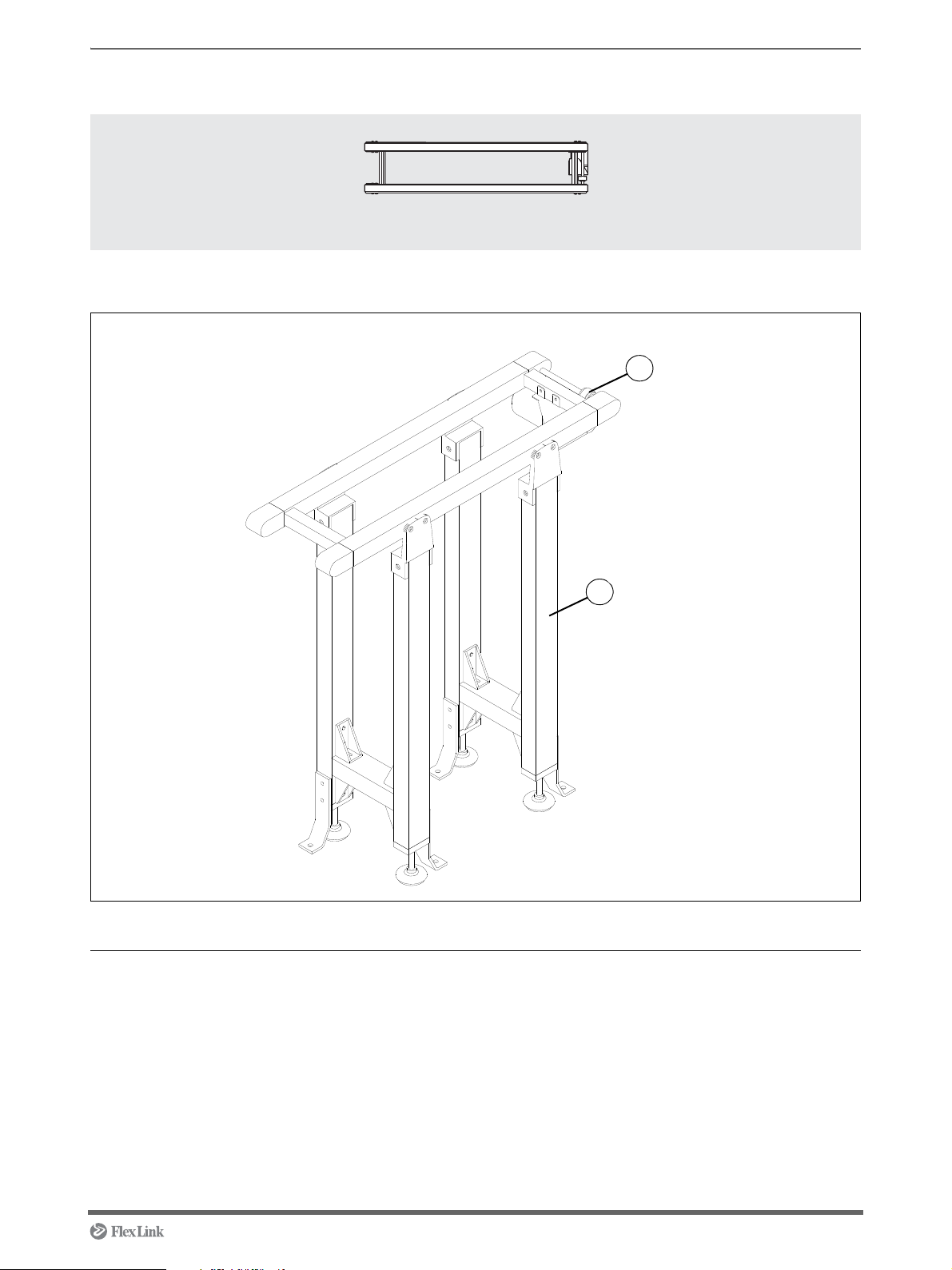
Conveyor module S11 Compact
XTUC S11
1
2
Overview
Assembly order
Pos Name Instruction
1 Connecting motor See page 19
2 Mounting support module See page 35
5113235 3
Page 4
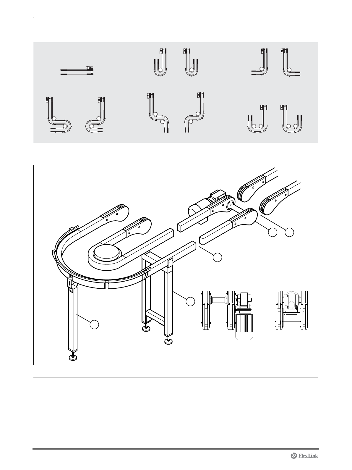
Conveyor modules
XTUC J51
XTUC J52
XTUC F51
XTUC F52
XTUC L51
XTUC L52
XTUC S51
XTUC U51
XTUC U52
XTUC Z51
XTUC Z52
1
2
3
4 5
Motor type L/R Motor type M/HM
Overview
Assembly order
Pos Name Instruction
1 Mounting support module See page 35
2 Mounting support module in bend See page 35
3 Docking XT conveyor sections See page 20
4 Mounting chain to XT conveyor modules See page 22
5 Connecting an XT conveyor module in line with another XT
4 5113235
conveyor:
-Motor type L or R See page 31
-Motor type M or HM See page 33
Page 5
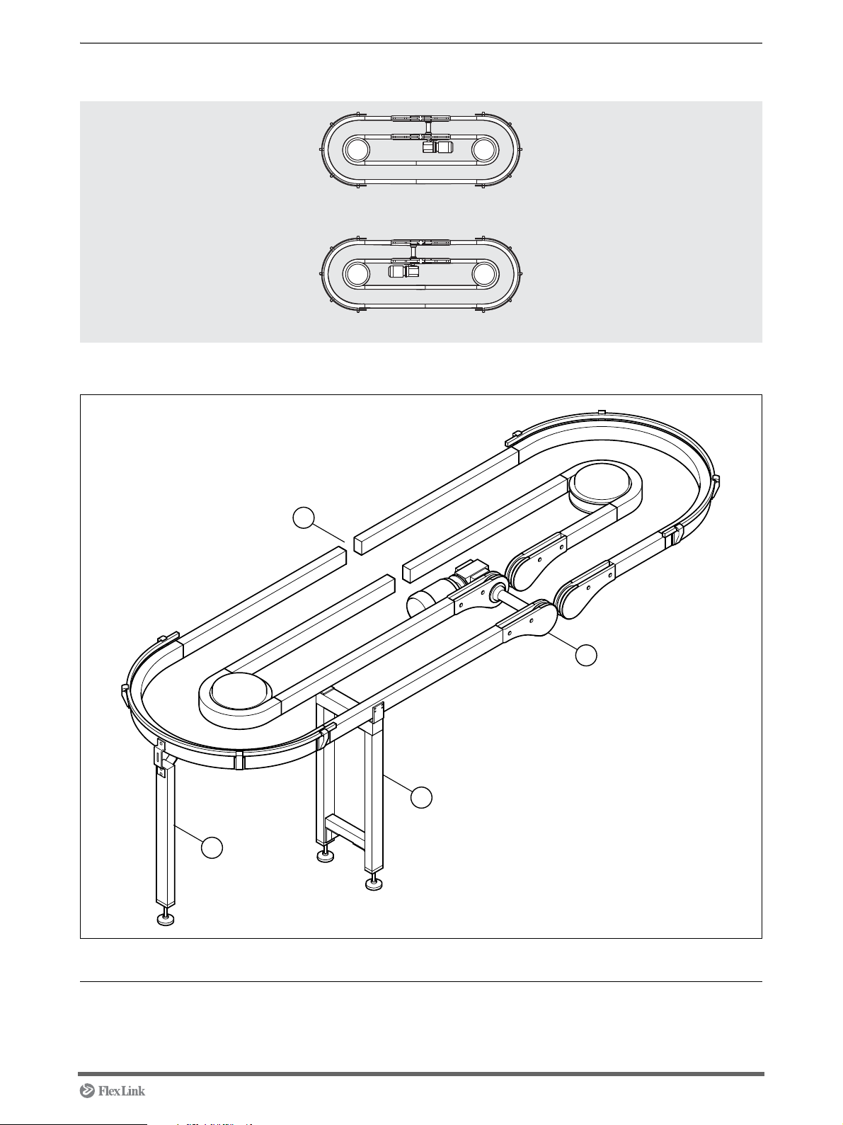
Conveyor module
XTUC Q51
XTUC Q52
1
2
3
4
Overview
Assembly order
Pos Name Instruction
1 Mounting support module See page 35
2 Mounting support module in bend See page 35
3 Docking XT conveyor sections See page 20
4 Mounting chain to XT conveyor module See page 26
5113235 5
Page 6
Support module S01A/S02A/S03A/S04
S 01A
S 03A
S 02A
S 04
1
1 1
1
Overview
Pos Name Instruction
1 Mounting support module See page 35
6 5113235
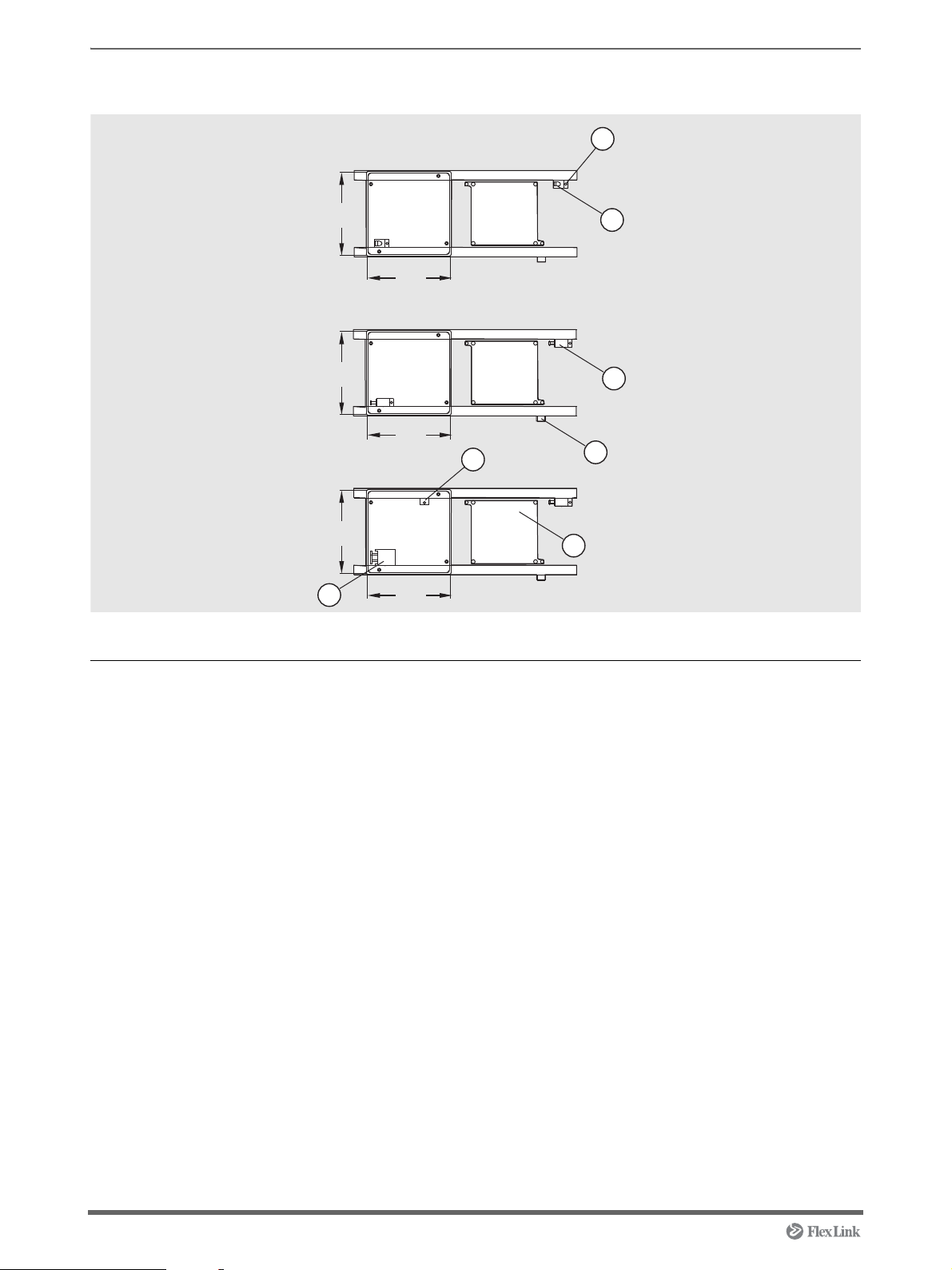
Page 7
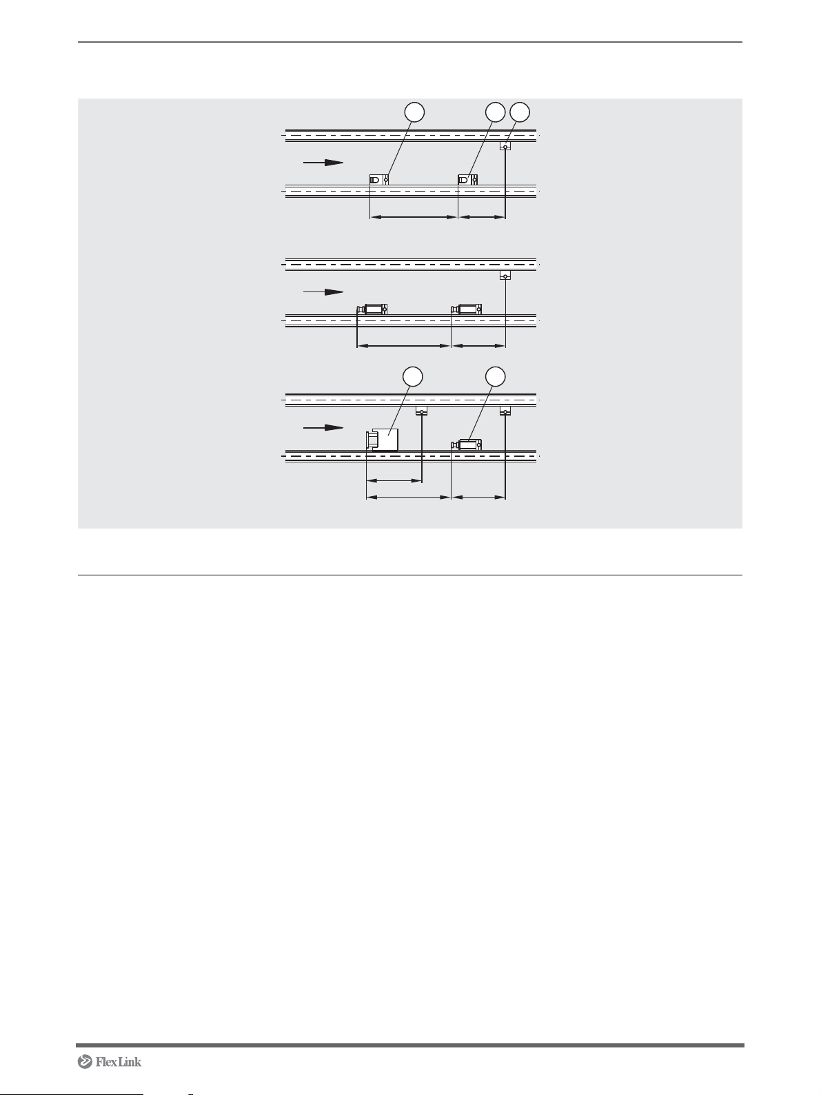
Stop function module P11
D = D00
D = D01
D = D02
PL-54
PL-54*
PL-54*
PL-54*
min PL+20
min PL+20*
min PL+20*
14
23
5
XTUS P11
Overview
* With stop heel compressed
Pos Name Designation Instruction
1 Pallet stop device XTPD U200 See page 38
2 Pallet stop device damped XTPD D35 See page 40
3 Pallet stop device damped XTPD D100 See page 42
4 Sensor bracket XTPB V001 See page 43
5 Sensor bracket XTPB V002 See page 45
5113235 7
Page 8
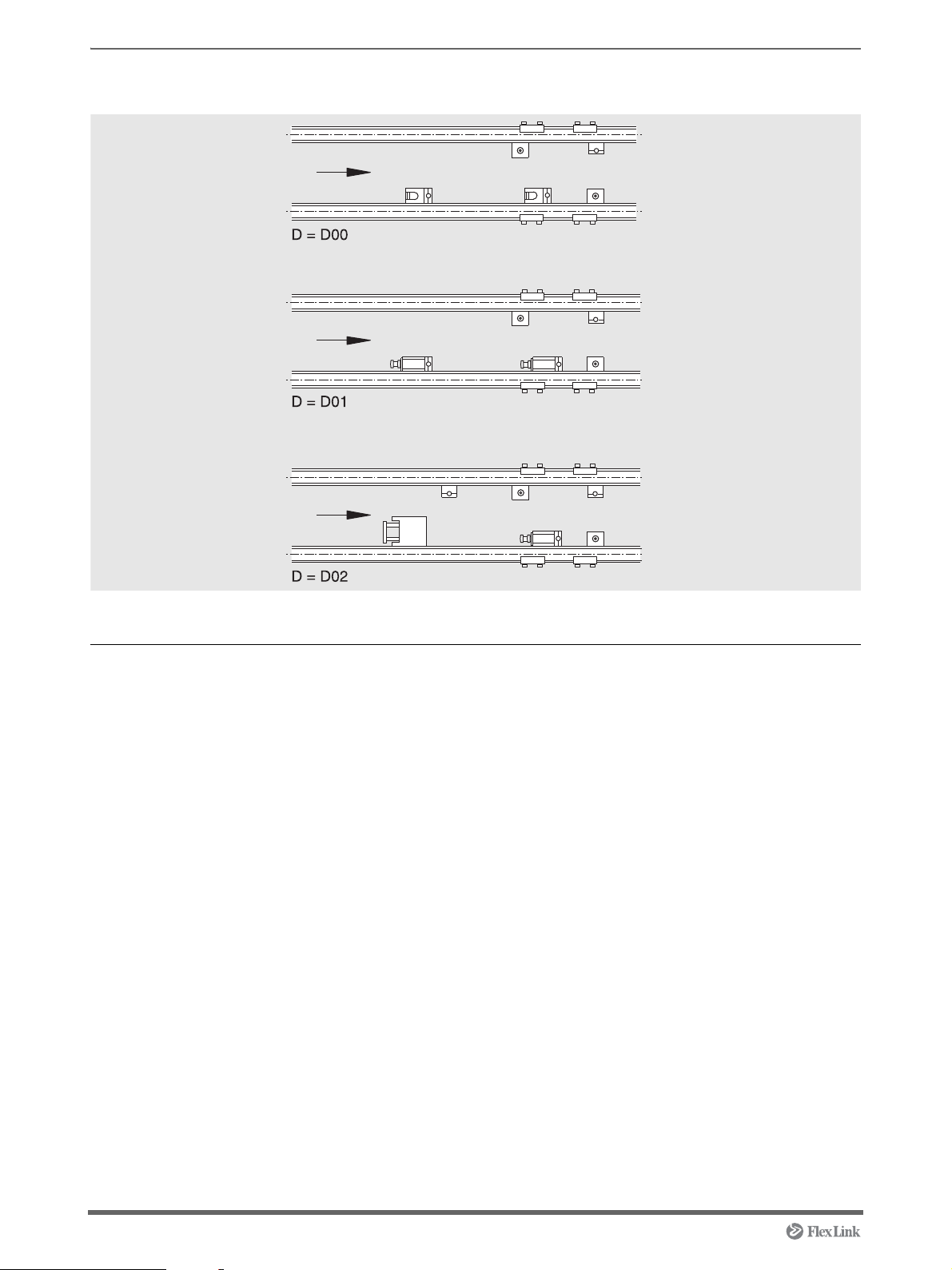
Locating function module P11A
Overview
Placement of stop and sensor brackets, see Stop function module P11.
Pos Name Designation Instruction
1 Pallet stop device XTPD U200 See page 38
2 Pallet stop device damped XTPD D35 See page 40
3 Pallet stop device damped XTPD D100 See page 42
4 Sensor bracket XTPB V001 See page 43
5 Sensor bracket XTPB V002 See page 45
6 Locating station XTPX P11A See page 52
8 5113235
Page 9
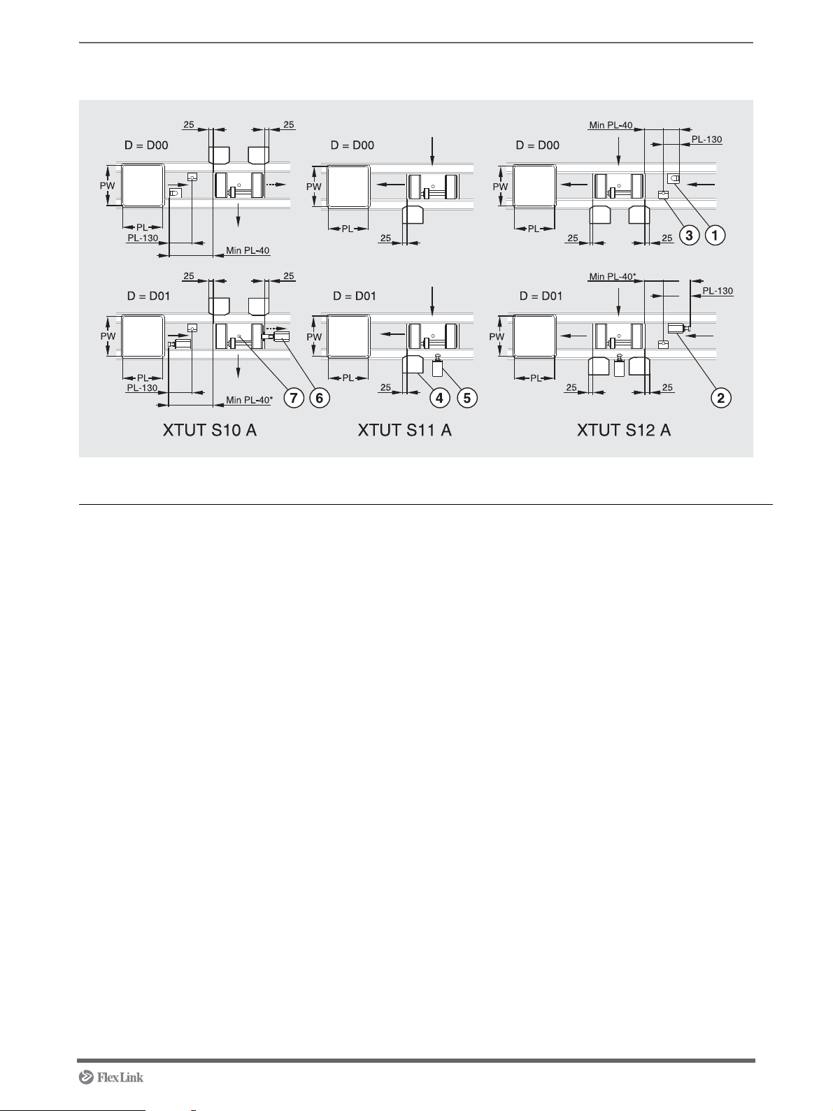
Transfer module S10 A/S11 A/S12 A
Overview
* With stop heel compressed
Pos Name Designation Instruction
1 Pallet stop device XTPD U200 See page 38
2 Pallet stop device damped XTPD D35 See page 40
3 Sensor bracket XTPB V002 See page 45
4 Position sensor XTPB V003 See page 46
5 Damper XTPA CM35 See page 49
6 Damper XTPA MC35 PW A See page 57
7 Mounting transfer unit XTPT See page 57
5113235 9
Page 10
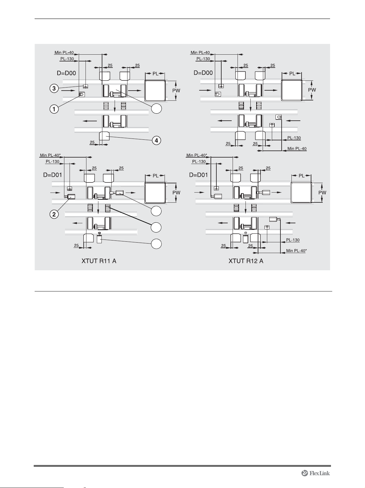
Transfer module R11 A/R12 A
8
5
7
6
Overview
* With stop heel compressed
Pos Name Designation Instruction
1 Pallet stop device XTPD U200 See page 38
2 Pallet stop device damped XTPD D35 See page 40
3 Sensor bracket XTPB V002 See page 45
4 Position sensor XTPB V003 See page 46
5 Damper XTPA CM35 See page 49
6 Roller kit 5049865, 5050117 See page 50
7 Damper XTPA MC35 PW A See page 57
8 Mounting transfer unit XTPT See page 57
10 5113235
Page 11
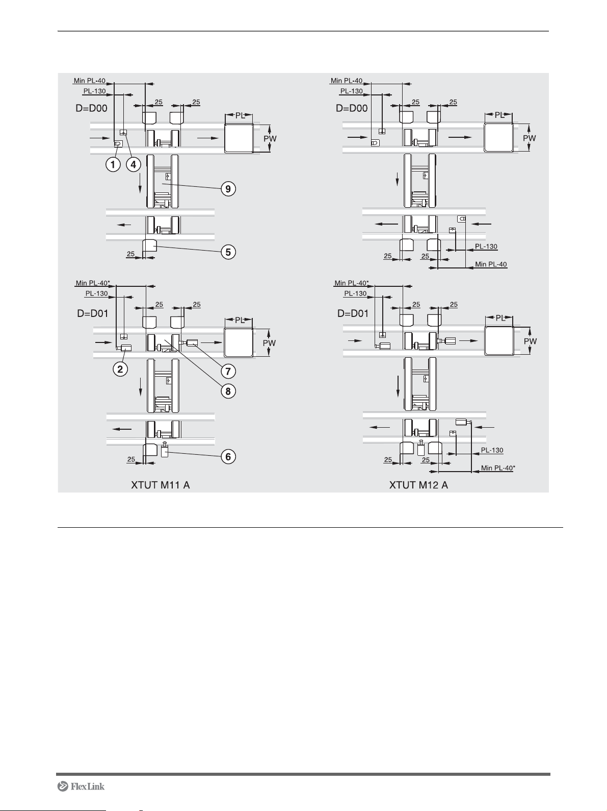
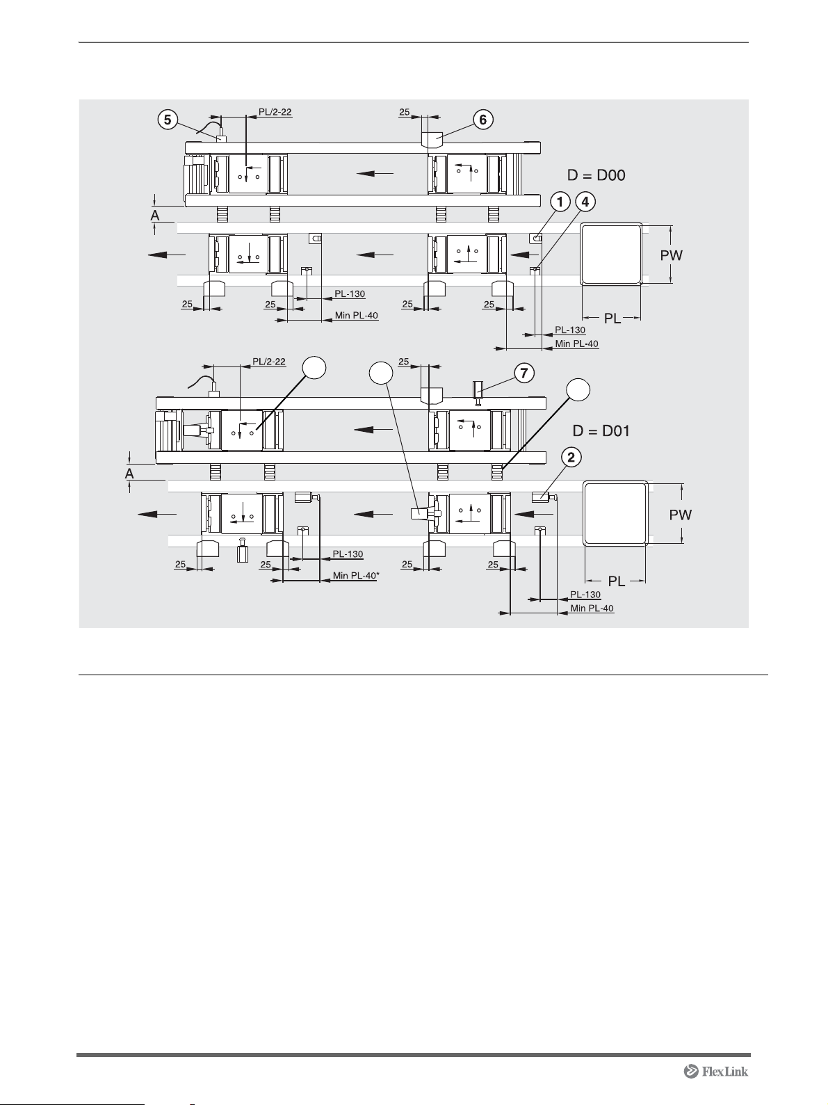
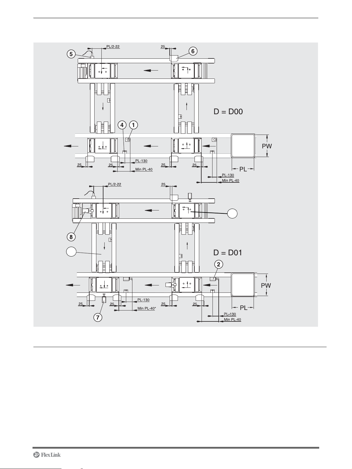
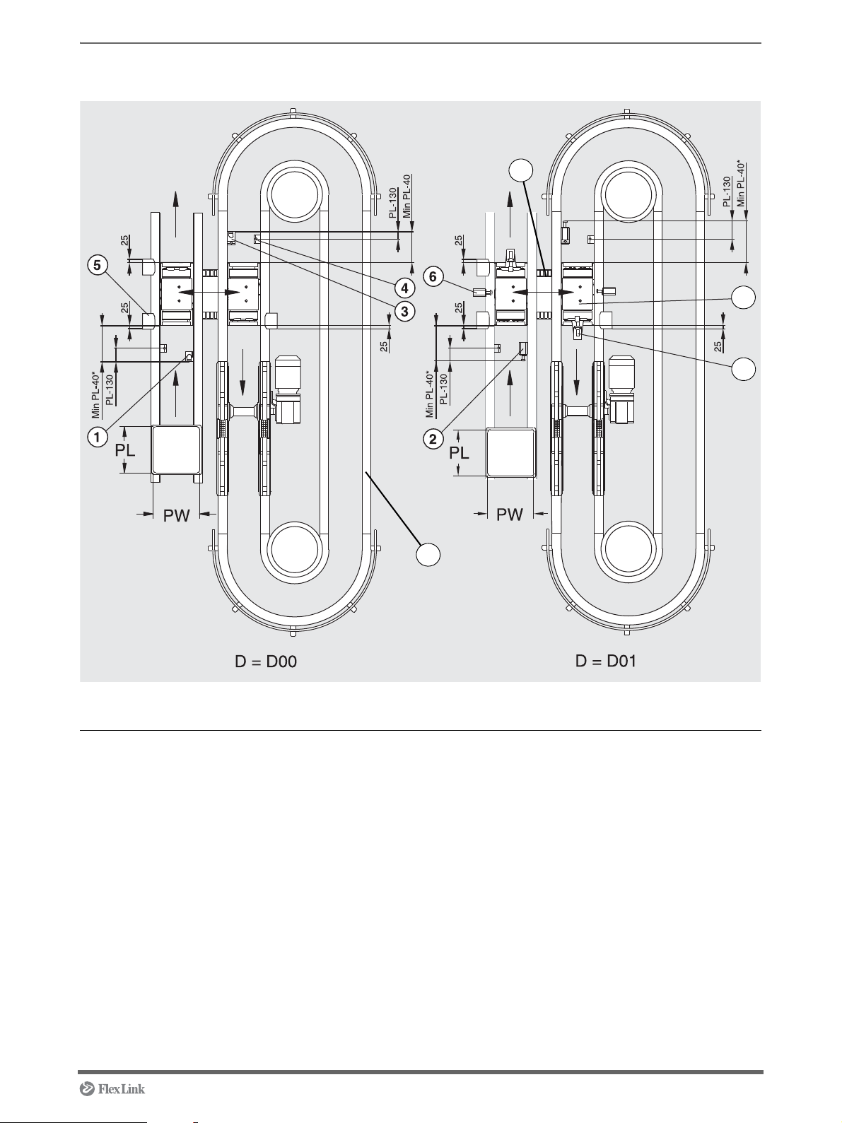
Transfer module M11 A/M12 A
Overview
* With stop heel compressed
Pos Name Designation Instruction
1 Pallet stop device XTPD U200 See page 38
2 Pallet stop device damped XTPD D35 See page 40
3 Sensor bracket (not in picture) XTPB V001 See page 43 (only for option Q01)
4 Sensor bracket XTPB V002 See page 45
5 Position sensor XTPB V003 See page 46
6 Damper XTPA CM35 See page 49
7 Damper XTPA MC35 PW A See page 57
8 Mounting transfer unit XTPT See page 57
9 Mounting connecting kit 5050034 See page 51
5113235 11
Page 12
Work station module R11 A
10
8
9
Overview
* With stop heel compressed
Pos Name Designation Instruction
1 Pallet stop device XTPD U200 See page 38
2 Pallet stop device damped XTPD D35 See page 40
3 Sensor bracket (not in picture) XTPB V001 See page 43 (only for option S01 &
L01).
4 Sensor bracket XTPB V002 See page 45
5 Sensor bracket XTPB H001 See page 48
6 Position sensor XTPB V003 See page 46
7 Damper XTPA CM35 See page 49
8 Roller kit 5049865, 5050117 See page 50
9 Damper XTPA MC35 PW A See page 57
10 Mounting transfer unit XTPT See page 57
12 5113235
Page 13
Work station module M11 A
9
10
Overview
* With stop heel compressed
Pos Name Designation Instruction
1 Pallet stop device XTPD U200 See page 38
2 Pallet stop device damped XTPD D35 See page 40
3 Sensor bracket (not in picture) XTPB V001 See page 43 (only for option Q01,
4 Sensor bracket XTPB V002 See page 45
5 Sensor bracket XTPB H001 See page 48
6 Position sensor XTPB V003 See page 46
7 Damper XTPA CM35 See page 49
8 Damper XTPA MC35 PW A See page 57
9 Mounting transfer unit XTPT See page 57
10 Mounting connecting kit 5050034 See page 51
5113235 13
S01 & L01).
Page 14

Work station module T11 A
6
8
7
Overview
Pos Name Designation Instruction
1 Pallet stop device XTPD U200 See page 38
2 Sensor bracket (not in picture) XTPB V001 See page 43 (only for option Q01,
S01 & L01).
3 Sensor bracket XTPB V002 See page 45
4 Sensor bracket XTPB H001 See page 48
5 Position sensor XTPB V003 See page 46
6 Roller kit 5049865,
5050117
7 Mounting connecting kit 5050034 See page 51
8 Mounting transfer unit XTPT See page 57
See page 50
14 5113235
Page 15
Work station module Q51 A
10
9
8
7
Overview
* With stop heel compressed
Pos Name Designation Instruction
1 Pallet stop device XTPD U200 See page 38
2 Pallet stop device damped XTPD D35 See page 40
3 Sensor bracket XTPB V001 See page 43
4 Sensor bracket XTPB V002 See page 45
5 Position sensor XTPB V003 See page 46
6 Damper XTPA CM35 See page 49
7 Roller kit 5049865, 5050117 See page 50
8 Damper XTPA MC35 PW A See page 57
9 Mounting transfer unit XTPT See page 57
10 Mounting conveyour module XTUC Q51 See page 5
5113235 15
Page 16
Lift and rotate module P11
PW
PL
PW
PW
PL
PL
5
3
7
6
2
1
4
D = D00
D = D01
D = D02
Overview
Pos Name Designation Instruction
1 Pallet stop device XTPD U200 See page 38
2 Pallet stop device, damped XTPD D35 See page 40
3 Pallet stop device, damped XTPD D100 See page 42
4 Sensor bracket XTPB V001 See page 43
5 Sensor bracket XTPB V002 See page 45
6 Sensor bracket XTPB H001 See page 48
7 Mounting lift and rotate unit XTUR P11 See page 68
16 5113235
Page 17
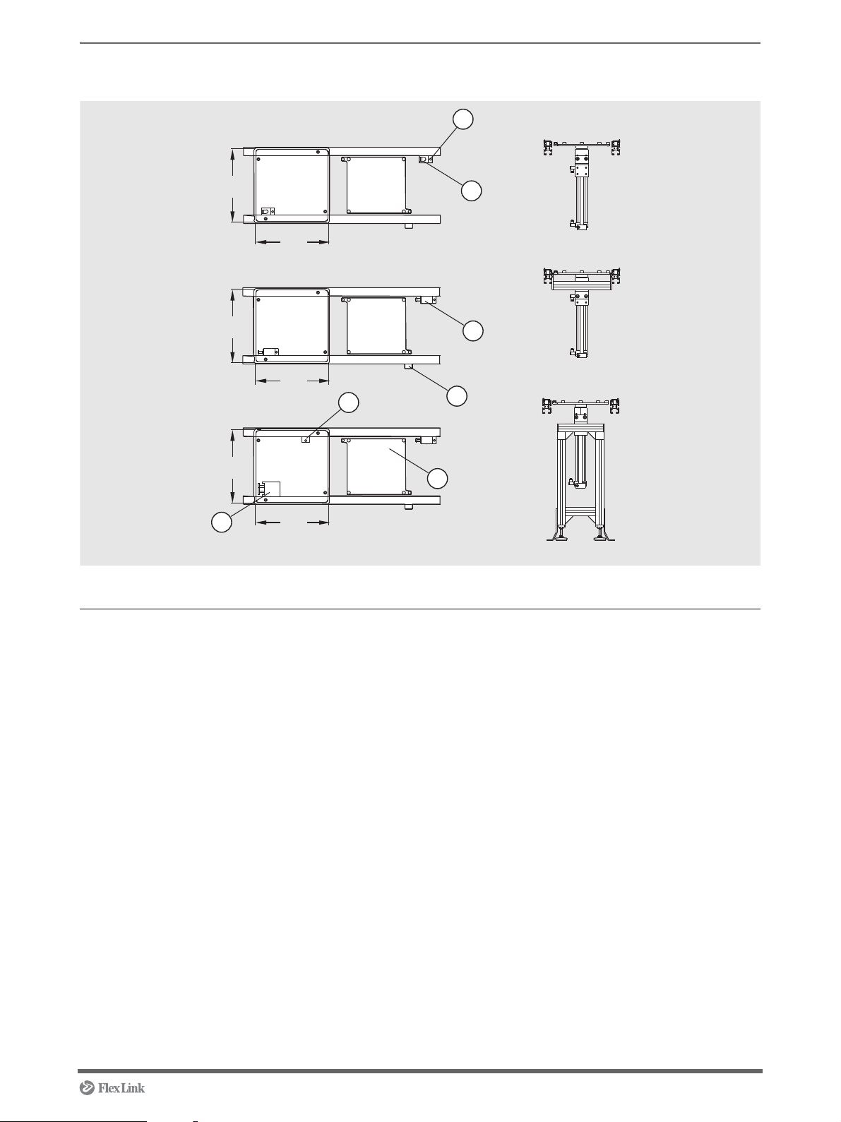
Lift and locate module P12
PW
PL
PW
PW
PL
PL
5
3
7
6
2
1
4
D = D00
D = D01
D = D02
F = F00
F = F01
F = F02
Overview
Pos Name Designation Instruction
1 Pallet stop device XTPD U200 See page 38
2 Pallet stop device, damped XTPD D35 See page 40
3 Pallet stop device, damped XTPD D100 See page 42
4 Sensor bracket XTPB V001 See page 43
5 Sensor bracket XTPB V002 See page 45
6 Sensor bracket XTPB H001 See page 48
7 Mounting lift and locate unit XTUL P12 See page 70
5113235 17
Page 18

Mounting instructions
Contents
Connecting motor XTUC S11...................................................................... 19
Docking XT conveyor sections ............................................ ... ... .... ... ... ... ... .. 20
Mounting chain to XT conveyor modules – End drive ................................. 22
Mounting chain to XT conveyor modules – Catenary drive ......................... 26
Connecting XT conveyor modules in line – Side mounted motor................ 31
Connecting XT conveyor modules in line – Centre mounted motor ............ 33
Mounting support module............................................................................ 35
Mounting pallet stop device XTPD U200..................................................... 38
Mounting pallet stop device XTPD D35....................................................... 40
Mounting pallet stop device XTPD D100..................................................... 42
Mounting sensor bracket XTPB V001.......................................................... 43
Mounting sensor bracket XTPB V002.......................................................... 45
Mounting position sensor XTPB V003......................................................... 46
Mounting sensor bracket XTPB H001 ......................................................... 48
Mounting damper CM 35............................................................................. 49
Mounting roller kit ........................................................................................ 50
Mounting connecting kit 5050034. ... .... ... ... ... ... .... ... ... ... .... ... ... ..................... 51
Mounting pallet locating station XTPX P11A............................................... 52
Mounting transfer unit XTPT M1.......................... ... ... ... .... ... ... ... .................. 57
Mounting transfer unit XTPT M2.......................... ... ... ... .... ... ... ... .................. 60
Mounting transfer unit XTPT L............................. ... ... ... .... ... ... ..................... 63
Mounting damper MC 35 PW A................................................................... 67
Mounting lift and rotate unit XTUR P11 ....................................................... 68
Mounting lift and locate unit XTUL P12 ....................................................... 70
18 5113235
Page 19
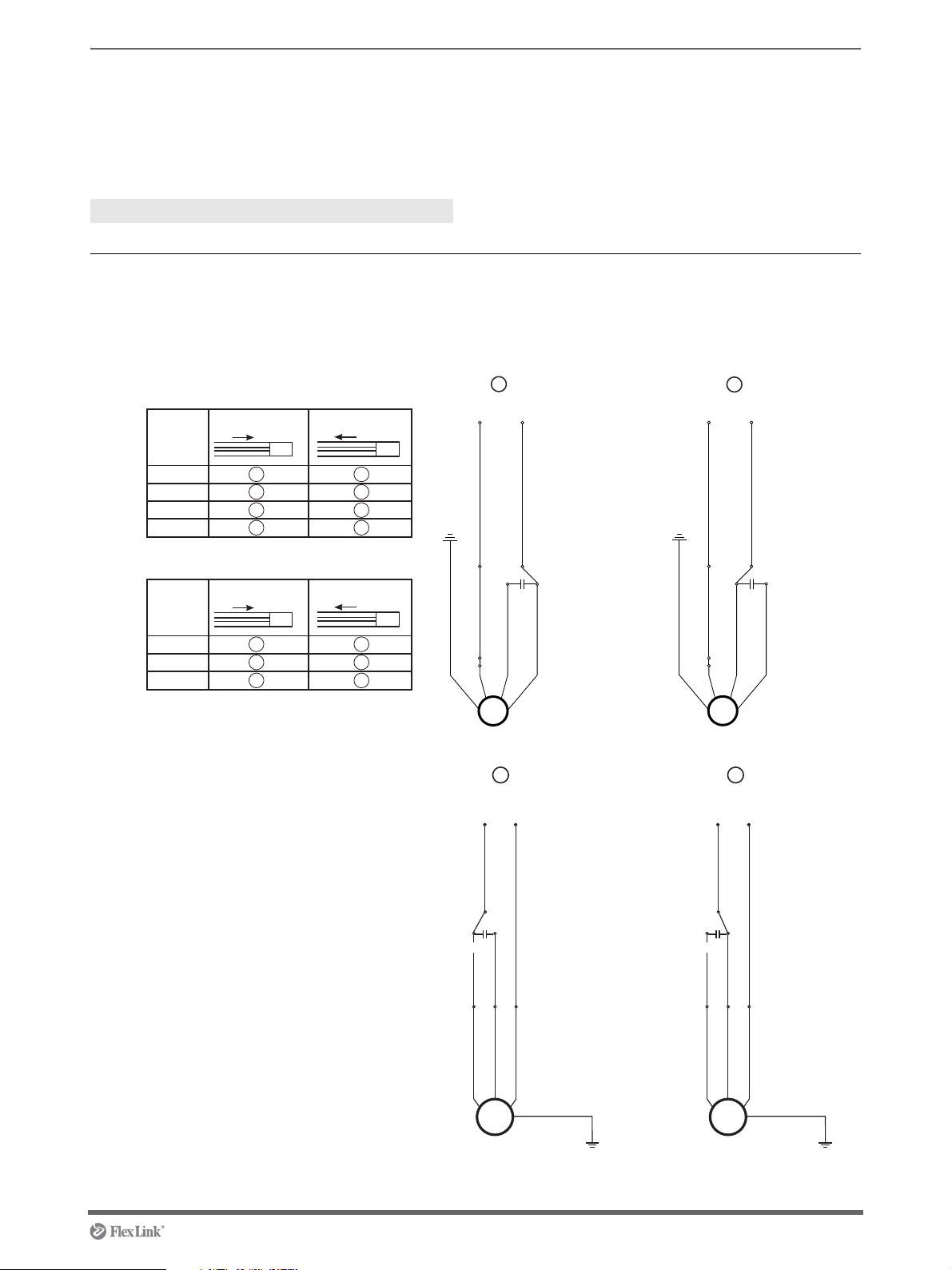
Connecting motor XTUC S11
Brown (No 2) On S8R25GE grey)
Brown (No 2) On S8R25GE grey)
Green/yellow
GND
Green/yellow
GND
Capacitor Capacitor
1
2
Neutral
Phase
Neutral
Phase
3 4
50 , 230V
Hz
60Hz,115V
Forward
Forward Reverse
Reverse
Speed
m/min
Speed
m/min
54
10
15
20
M
M
6
12
18
M
M
3
3 4
3 4
4 3
2 1
1 2
1 2
Black (No 3)
White (No 1)
Black (No 3)
White (No 1)
Green/Yellow (No 4)
Black (No 3)
White (No 1)
Grey (No 2)
Phase
Neutral
T/P
Capacitor
Green/Yellow (No 4)
Black (No 3)
White (No 1)
Grey (No 2)
Phase
Neutral
T/P
Capacitor
M
MMM
MM
GND
GND
Introduction
NOTE! The capacitor must alwa ys be encapsulated to
prevent electric shock.
Tools
- -
Instruction
1 Connect the motor according to wiring diagram
below.
5113235 19
Page 20
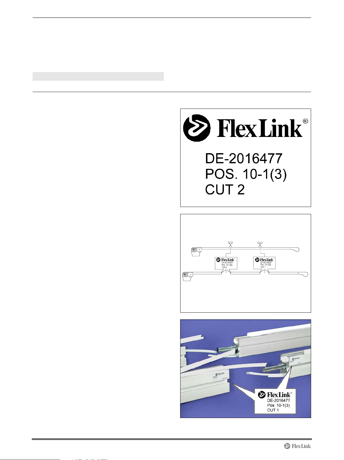
Docking XT conveyor sections
Introduction
This instruction is only valid for conveyor XT. NOTE! A short or narrow conveyor can easily fall over.
Always anchor the conveyor to the floor!
Tools
Allen key 4 mm
Instruction
1 The section labels indicate following:
First row is the order number.
Second row indicates the item position on the
order and which individual among a quantity, e.g.
Pos. 10 first conveyor of three.
The third row indicates which cut it is.
Two sections with identical labels should be
connected to each other.
2 Unpack the conveyor sections and arrange them
so that beam ends with identical labels are facing
each other. Place the conveyor sections on the
same level and in line with each other.
3 Dock the conveyor sections to each other.
20 5113235
Page 21
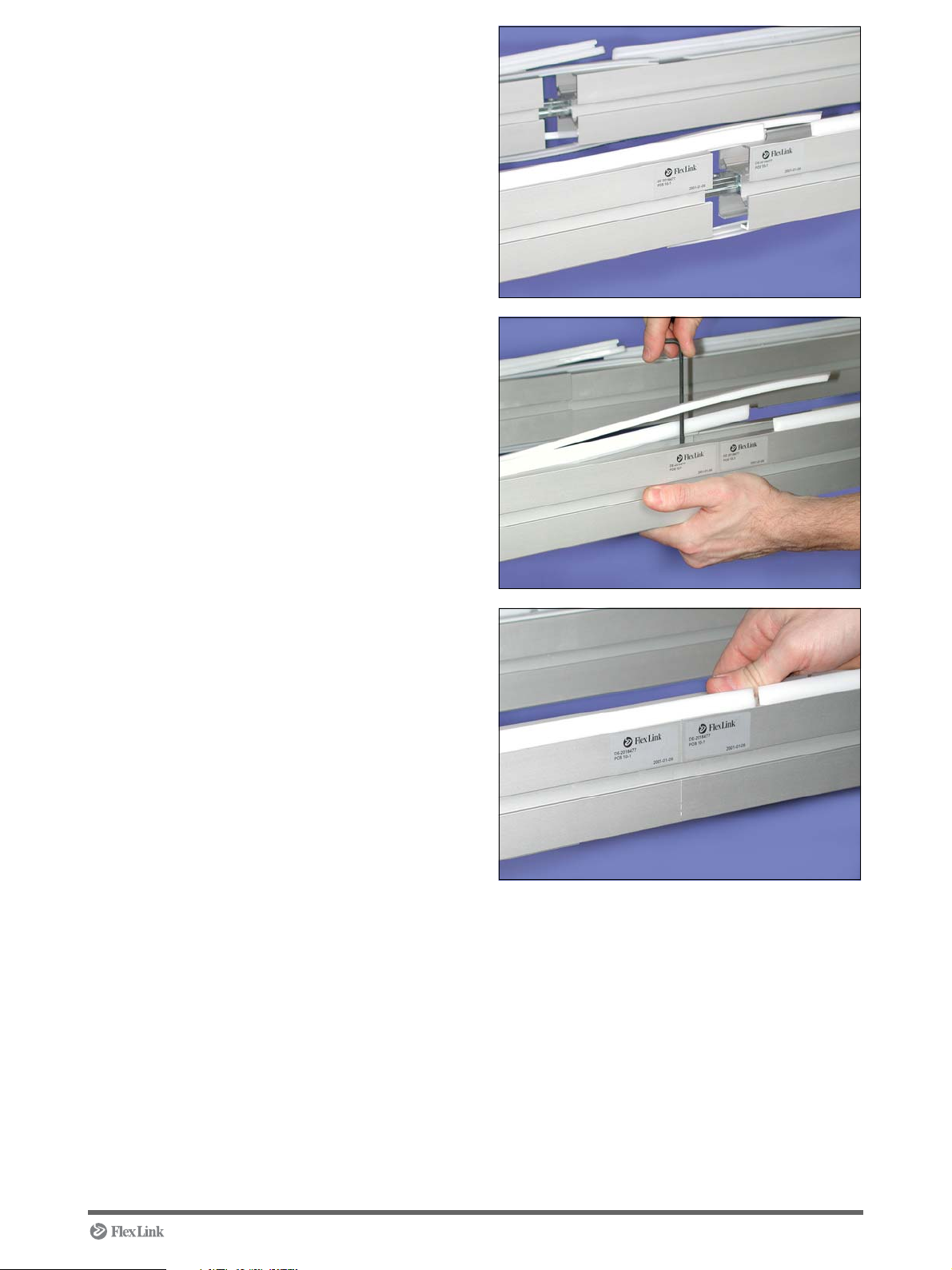
4 Make sure that the conveyor section ends fit
together properly.
5 Tighten the screws. Use the 4 mm allen key.
Torque value for tightening: 8 Nm
6 Press the slide rail in place.
5113235 21
Page 22
Mounting chain to XT conveyor modules – End drive
Introduction
Valid for motor types M and HM (centre mounted
motor) and L and R (side mounted motor). If nothing
else is specified the instruction step is valid for both
centre and side mounted motor.
Tools
Box wrench 10 mm
Box wrench 7 mm
Skip joint pliers
Pin insertion tool
Screwdriver
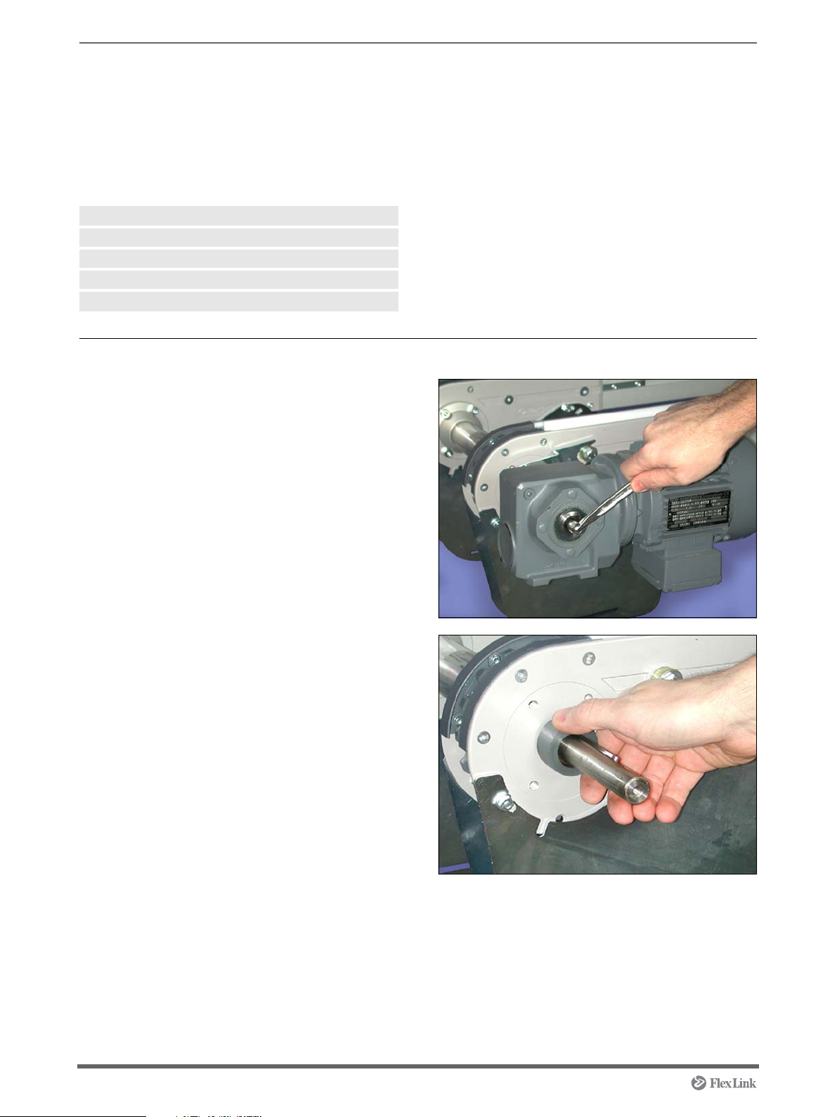
Instruction
1 Side mounted motor:
Use the screwdriver to remove the plastic cap on
the motor. Loosen the screw for the motor with
the 10 mm socket wrench.
2 Side mounted motor:
Lift off the motor and remove the plastic sleeve.
22 5113235
Page 23
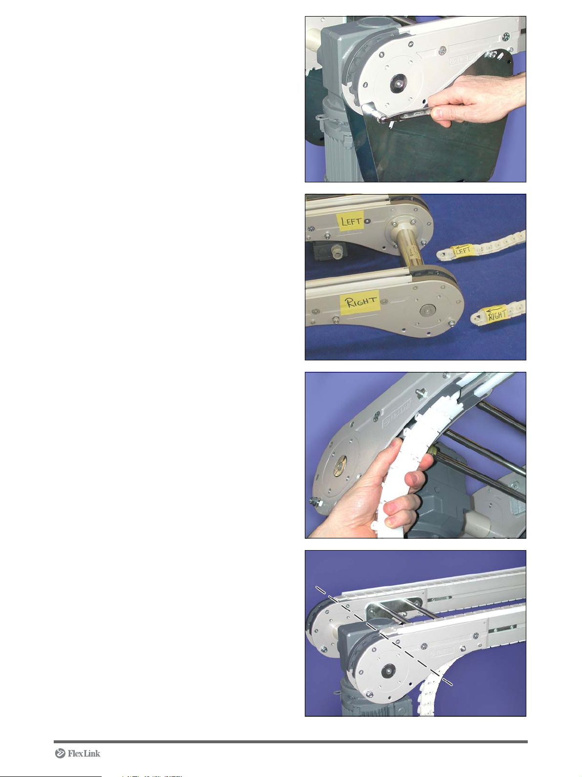
3 Remove the nuts for the slack protection. Use a
10 mm box wrench.
4 Notice the label Left and Right on the chain.
Mount the chain to the conveyor with similar
mark.
5 Insert the chain from below, with the nose for-
ward.
Repeat the same procedure with the other chain.
6 Feed the chains into the conveyor until they
reach the drive wheel at the driving end.
5113235 23
Page 24

7 Centre mounted motor (A):
B
A
Check rib down
A
Remove the fan cover. Use the 7 mm box
wrench. Feed the chains to the drive wheel and
turn the fan until the chains are hanging a bit
below the conveyor.
Side mounted motor (B):
Feed the chains to the drive wheel and turn the
drive shaft until the chains are hanging a bit
below the conveyor.
CAUTION! Make sure that the chain enters the
drive wheel correctly. Risk for the plastic guides
to brake.
8 Use a pair of slip joint pliers to insert the pin half-
way into the chain link.
9 Join the chain ends. Make sure that the joint ball
has not been removed and re-assembled upside
down.
CAUTION! Wrongly positioned joint ball will lead
to chain damage when running the chain.
10 Press the pin through the chain. Use the pin
insertion tool.
TIP! Use a clamp (A) to keep the chain stretched.
24 5113235
Page 25

11 Make sure that the pin snaps in to the correct
position (centered).
12 Centre mounted motor:
Fit the fan cover to the motor and tighten the
screws. Use the 7 mm box wrench. Fit the slack
protections and tighten the nuts. Use the 10 mm
box wrench.
Side mounted motor:
Fit the slack protections and tighten the nuts.
Use the 10 mm box wrench.
13 Side mounted motor:
Fit the plastic sleeve on the drive shaft.
14 Side mounted motor:
Fit the motor on the drive shaft and tighten the
screw. Use a 10 mm socket wrench. Fit the
plastic cap.
CAUTION! Make sure that the torque arm fork
has entered the cage in a correct way. An
unlocked rotating motor can cause personal
injury.
5113235 25
Page 26

Mounting chain to XT conveyor module – Catenary drive
Introduction
The chain only runs on top of the conveyor.
Tools
Box wrench 10 mm
Skip joint pliers
Pin insertion tool
Screwdriver
Instruction
1 Use the screwdriver to remove the plastic cap on
the motor. Loosen the screw for the motor with
the 10 mm socket wrench.
2 Lift off the motor and remove the plastic sleeve.
26 5113235
Page 27

3 Notice the label Left and Right on the chain.
Mount the chain to the conveyor with similar
mark.
4 Insert the chain from below, with the nose for-
ward.
CAUTION! Make sure that you start feeding the
chain in the idler end unit and towards the driving
unit or it might lead to a chain damage.
5 Catch the chain and feed it via the idler end into
the conveyor. Repeat the same procedure with
the other chain.
6 Feed the chains into the conveyor until they
reach the drive wheel at the driving end.
5113235 27
Page 28

7 Feed the chains to the drive wheel and turn the
Check rib down
drive shaft until the chains are hanging a bit
below the conveyor.
CAUTION! Make sure that the chain enters the
drive wheel correctly. Risk for the plastic guides
to brake.
8 Use a pair of slip joint pliers to insert the pin half-
way into the chain link.
9 Join the chain endings. Make sure that the joint
ball has not been removed and re-assembled
upside down.
CAUTION! Wrongly positioned joint ball will lead
to chain damage when running the chain.
10 Press the pin through the chain. Use the pin
insertion tool.
28 5113235
Page 29

11 Make sure that the pin snaps in to the correct
position (centered).
12 Fit the slack protection covers to end position.
13 Fit and tighten the screws (4 x M6). Use the 10
mm box wrench.
14 Fit the plastic sleeve on the drive shaft.
5113235 29
Page 30

15 Fit the motor on the drive shaft.
16 Fit and tighten the screw. Use the 10 mm socket
wrench. Fit the plastic cap.
CAUTION! Make sure that the torque arm fork
has entered the cage in a correct way. An
unlocked rotating motor can cause personal
injury.
17 Place the roller bridge between the conveyors.
30 5113235
Page 31

Connecting an XT conveyor module, side mounted motor in line with another XT conveyor
Introduction
Use connecting kit 5049594, which connects a side
mounted end drive unit (L and R), to an idler end unit.
Tools
Allen key 5 mm
Box wrench 13 mm
Instruction
1 Make sure that the conveyors are on the same
level and in line with each other.
Loosen the screw for the torque arm. Use the 13
mm box wrench. Lower the motor.
CAUTION! Fit one connecting plate at a time to
ensure the unit remains intact, never
for more than one connecting plate at a time.
loosen screws
2 Loosen the screws (3 x M8) on the side plates.
Use the 5 mm allen key.
CAUTION! Fit one connecting plate at a time to
ensure the unit remains intact, never
screws for more than one connecting plate at a
time.
loosen
5113235 31
Page 32

3 Fit the connecting plate and tighten the screws.
Use the 5 mm allen key.
4 Turn up the motor. Fit and tighten the screw for
torque arm. Use the 13 mm box wrench.
CAUTION! Make sure that the torque arm fork
has entered the cage in a correct way. An
unlocked rotating motor can cause personal
injury.
5 Fit the remaining connecting plates. Place the
roller bridge between the conveyors.
CAUTION! Fit one connecting plate at a time to
ensure the unit remains intact, never
screws for more than one connecting plate at a
time.
6 Use a ruler to make sure that the roller bridge is
in the correct vertical position. Max distance
between ruler and roller: 1 mm.
If needed, loosen the screws for the connecting
plates again and adjust until the necessary
space is obtained.
loosen
32 5113235
Page 33

Connecting an XT conveyor module, centre mounted motor in line with another XT conveyor
Introduction
Use connecting kit 5050564, which connects a centre
mounted end drive unit (M and HM), to an idler end
unit
.
Tools
Allen key 5 mm
Box wrench 13 mm
Instruction
1 Make sure that the conveyors are on the same
level and in line with each other.
Loosen the screws (4 x M8) on the side plates.
Use the 5 mm allen key.
CAUTION! Fit one connecting plate at a time to
ensure the unit remains intact, never
screws for more than one connecting plate at a
time.
loosen
CAUTION! Fit one connecting plate at a time to
ensure the unit remains intact, never
for more than one connecting plate at a time.
loosen screws
2 Fit the connecting plate and tighten the screws.
Use the 5 mm allen key.
5113235 33
Page 34

3 Fit the screws (4 x M8) to the inside of the side
plates at the driving end
4 Loosen the screws on the inside of the side plate
at the idler end. Use the 5 mm allen key. Fit the
inner connecting plate and tighten the screws.
Use a 13 mm box wrench and 5 mm allen key.
5 Fit the remaning plates. Place the roller bridge
between the conveyors.
CAUTION! Fit one connecting plate at a time to
ensure the unit remains intact, never
screws for more than one connecting plate at a
time.
6 Use a ruler to make sure that the roller bridge is
in the correct vertical position. Max distance
between ruler and roller: 1 mm.
If needed, loosen the screws for the connecting
plates again and adjust until the necessary
space is obtained.
loosen
34 5113235
Page 35

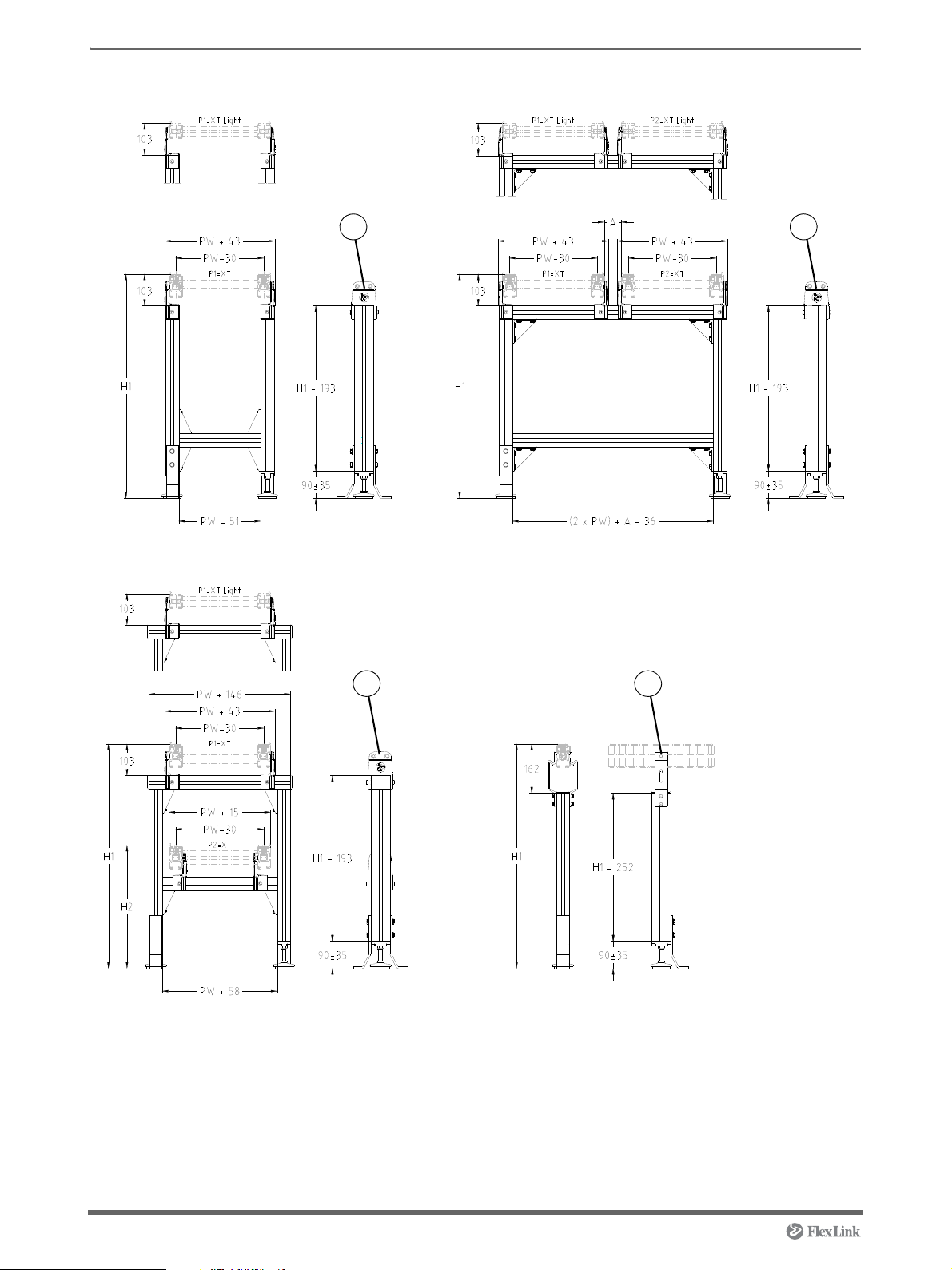
Mounting support module
XT
XT
Compact
Introduction
NOTE! Always place a support module near the
motor, where the weight is high.
CAUTION! A short conveyor, which has the point of
gravity near the motor, can easily cause the conveyor
to tilt.
Tools
Allen key 5 mm
Allen key 6 mm
Box wrench 13 mm
Box wrench 19 mm
Drilling-machine
Instruction
1 Place the support modules beside each other.
Make sure that the support modules has the
same height. If needed, adjust the feet. Use the
19 mm box wrench.
If nothing else is specified the instruction steps are
valid for all support modules.
2 XTUF S01A/S02A/S03A
There are different brackets for fitting the support
module on to an XT or XT Compact conveyor.
The XT bracket is a little bit lower than the XT
Compact bracket and uses M8 screws instead of
M5.
Loosen the screws (2xM8) on one of the
brackets of the support module using a 6 mm
Allen key.
NOTE! If the support is made for more than one
conveyor loosen one bracket in a pair for each
conveyor.
5113235 35
Page 36

3 XTUF S01A/S02A/S03A
XT Conveyor:
Insert the slot nuts (4 x M8) in the conveyor Tslot. Place the support module in the correct
position by tilting aside the loose bracket. Fit the
screws (4 x M8) and tighten with the 6 mm Allen
key. Tighten the screws (2 x M8) on the loose
bracket using the 6 mm Allen key.
XT Compact Conveyor:
Insert the slot nuts (4 x M5) in the conveyor Tslot. Place the support module in the correct
position by tilting aside the loose bracket. Fit the
screws (4 x M5) and tighten with the 5 mm Allen
key. Tighten the screws (2 x M8) on the loose
bracket using the 6 mm Allen key.
4 XTUF S04
Insert the slot nuts (2 x M8) in the conveyor T-slot
at the centre of the bend.
Place the support module in correct position. Fit
and tighten the screws (2 x M6). Use the 13 mm
box wrench.
5 Fit the slot nuts (2 x M8) to the support beam T-
slot.
Fit the foot and tighten the screws (2 x M8). Use
the 13 mm box wrench.
36 5113235
Page 37

6 Mount the foot to the surface.
5113235 37
Page 38

Mounting pallet stop device XTPD U200
Introduction
The stop can be placed on the inside of the conveyor
at either the left (stop at pallet front) or right side (stop
at pallet back). If nothing else is specified the
instruction steps are valid for both XT and XT
Compact conveyors.
Tools
Allen key 6 mm
Allen key 5 mm
Instruction
1 XT conveyor:
Insert the slot nuts (2 x M8) in the conveyor Tslot. Insert the bushings to the stop unit.
2 XT conveyor:
Fit the screws (2 x M8).
NOTE! The stop flange shall face against the
pallet direction of travel.
38 5113235
Page 39

3 XT conveyor:
P
a
l
l
e
t
d
i
r
e
c
t
i
o
n
Use the 6 mm Allen key to tighten the screws.
Torque value for tightening: 25 Nm.
4 XT Compact conveyor:
Mount the bracket on the unit. Fit and tighten the
screws (2 x M6) with the 5 mm Allen key. Torque
value for tightening: 10 Nm.
5 XT Compact conveyor:
Insert the slot nuts (2 x M6) in the conveyor Tslot.
Fit and tighten the screws (2 x M6). Use the 5
mm Allen key. Torque value for tightening: 10
Nm.
NOTE! The stop flange shall face against the
pallet direction of travel.
5113235 39
Page 40

Mounting pallet stop device XTPD D35
Introduction
The stop can be placed on the inside of the conveyor
at either the left (stop at pallet front) or right side (stop
at pallet back). If nothing else is specified the
instruction steps are valid for both XT and XT
Compact conveyors.
Tools
Allen key 6 mm
Allen key 5 mm
Instruction
1 XT conveyor:
Insert the slot nuts (2 x M8) in the conveyor Tslot. Insert the bushings to the stop unit.
2 XT conveyor:
Fit the screws (2 x M8).
NOTE! The stop flange shall face against the
pallet direction of travel.
3 XT conveyor:
Use the 6 mm Allen key to tighten the screws.
Torque value for tightening: 25 Nm.
CAUTION! Too high torque can cause the unit to
get jamed.
40 5113235
Page 41

4 XT Compact conveyor:
P
a
l
l
e
t
d
i
r
e
c
t
i
o
n
Mount the bracket on the unit. Fit and tighten the
screws (2 x M6) with the 5 mm Allen key. Torque
value for tightening: 10 Nm.
5 XT Compact conveyor:
Insert the slot nuts (2 x M6) in the conveyor Tslot.
Fit and tighten the screws (2 x M6). Use the 5
mm Allen key.
NOTE! The stop flange shall face against the
pallet direction of travel.
6 Pre adjust the damping screw according to the
following:
a) Turn the screw clockwise towards the “+” sign
until it reaches the end position. When you have
reached the end position turn it counter
clockwise 360° towards the “-” sign.
b) Fine adjust the damping when the system is
running. Turn the screw to the “+” sign to
increase the damping and to the “-” sign to
decrease the damping.
CAUTION! Heavy pallets in combination with an
over damped stop can damage the stop.
7 Mount the cover.
5113235 41
Page 42

Mounting pallet stop device XTPD D100
Introduction
Mount the stop inside of the XT conveyor beam.
Tools
Allen key 6 mm
Instruction
1 Insert the slot nuts (2xM8) in the conveyor T-slot.
Insert the bushings to the stop unit.
2 Fit the screws (2 x M8).
NOTE! The stop flange shall face against the
pallet direction of travel.
3 Tighten the screws with the 6 mm Allen key.
Torque value for tightening: 25 Nm.
42 5113235
Page 43

Mounting sensor bracket XTPB V001 to pallet stop device XTPD U200 or XTPD D35
Introduction
The sensor is not included in sensor bracket V001. If
nothing else is specified the instruction steps are valid
for both XTPD U200 and XTPD D35.
Tools
Allen key 3 mm
Screwdriver
Instruction
1XTPD D35
Remove the cover with a screwdriver.
2 XTPD U200
Use the screws (2 x M4) to mount the sensor
bracket to the stop unit.
5113235 43
Page 44

3XTPD D35
Use the screws (2 x M4) to mount the sensor
bracket to the stop unit.
4 Fit the sensor to the sensor bracket.
5 Tighten the screws. Use the 3 mm Allen key.
44 5113235
Page 45

Mounting sensor bracket XTPB V002
Introduction
The sensor is not included in sensor bracket XTPB
V002.
Tools
Allen key 5 mm
Allen key 3 mm
Instruction
1 Insert the slot nuts (2 x M6) in the conveyor T-
slot. Fit the screws (2 x M6). The arrow shows
the upper holes for fitting on XT Compact
conveyor.
2 Use the 5 mm Allen key to tighten the screws.
3 Fit the sensor to the sensor bracket. Tighten the
screws. Use the 3 mm Allen key.
5113235 45
Page 46

Mounting position sensor XTPB V003
Introduction
The sensor is not included in position sensor XTBP
V003.
Mount the position sensor on the outside of
conveyor XT or XT Compact. If nothing else is
specified the instruction steps are valid for both XT
and XT Compact conveyors.
Tools
Allen key 3 mm
Allen key 5 mm
Allen key 6 mm
Instruction
1 Fit the sensor to the sensor bracket.
2 Tighten the screws. Use the 3 mm Allen key.
46 5113235
Page 47

3 XT conveyor:
Insert the slot nuts (2 x M8) in the conveyor Tslot. Mount the bushings to the sensor bracket.
XT Compact conveyor:
Insert the slot nuts (2 x M6) in the conveyor Tslot.
4 XT conveyor:
Fit the screws (2 x M8).
XT Compact conveyor:
Fit the screws (2 x M6). The arrow shows the
upper holes for fitting on XT Compact conveyor.
5 XT conveyor:
Use the 6 mm Allen key to tighten the screws.
XT Compact conveyor:
Use the 5 mm Allen key to tighten the screws.
5113235 47
Page 48

Mounting sensor bracket XTPB H001
Introduction
The sensor is not included in sensor bracket XTBP
H001.
Mount the bracket on the outside of conveyor
XT or XT Compact.
Tools
Allen key 3 mm
Allen key 5 mm
Instruction
1 Insert the slot nuts (2 x M6) in the conveyor T-
slot. Fit the screws (2 x M6). The arrow shows
the upper holes for fitting on XT Compact
conveyor.
2 Use the 5 mm Allen key to tighten the screws.
3 Fit the sensor to the sensor bracket. Tighten the
screws. Use the 3 mm Allen key.
48 5113235
Page 49

Mounting damper CM 35
Introduction
Mount the damper outside of conveyor XT or XT
Compact.
Tools
Box wrench 10 mm
Screwdriver
Instruction
1 Insert the slot nuts (2 x M6) in the conveyor T-
slot. Fit the screws (2 x M6).
The arrow shows the upper holes for fitting on XT
Compact conveyor.
2 Tighten the screws. Use the 10 mm box wrench.
3 Pre adjust the damping screw according to the
following:
a) Turn the screw clockwise towards the “+” sign
until it reaches the end position. When you have
reached the end position turn it counter
clockwise 360° towards the “-” sign.
b) Fine adjust the damping when the system is
running. Turn the screw to the “+” sign to
increase the damping and to the “-” sign to
decrease the damping.
CAUTION! Heavy pallets in combination with an
over damped stop can damage the stop.
5113235 49
Page 50

Mounting roller kit
Introduction
Use roller kit 5049865 (65 mm) or roller kit 5050117
(45 mm).
Tools
Box wrench 10 mm
Instruction
1 Insert the slot nuts (4 x M6) in the conveyor T-
slot.
2 Mount the roller to the conveyor. Fit and tighten
the screws (4 x M6). Use the 10 mm box wrench.
The arrow shows the upper holes for fitting on XT
Compact conveyor.
The distance between the two flanges shall be:
Pallet Length (PL) + 2 mm.
3 Place the conveyors parallel to each other. Make
sure that the conveyors are on the same level
and in a horizontal position.
Fit and tighten the screws (4 x M6). Use the 10
mm box wrench.
50 5113235
Page 51

Mounting XT Compact conveyor perpendicular to XT or XT Compact conveyor
Introduction
Use connecting kit 5050034.
Tools
Box wrench 8 mm
Instruction
1 Loosen the screws on the XT Compact conveyor
(2 x M5). Use the 8 mm box wrench. Insert the
slot nut (1 x M5) in the conveyor T-slot.
2 Mount the bracket. Fit and tighten the screws
(2 x M5). Use the 8 mm box wrench.
3 Fit and tighten the screw (1 x M5). Use the 8 mm
box wrench. The arrow shows the upper holes for
fitting on XT Compact conveyor.
5113235 51
Page 52

Mounting pallet locating station XTPX P11A
Introduction
Mount the locating station on conveyor XT or XT
Compact. If nothing else is specified the instruction
step is valid for both XT and XT Compact conveyor.
Tools
Soft faced hammer
Allen key 6 mm
Adjustable wrench
Box wrench 10 mm
Piece of slide rail 4 pcs
Instruction
1 Mount the pins to the locating units.
2 Use a soft faced hammer and hit the pin carefully
until it reaches the end position.
52 5113235
Page 53

3 XT conveyor:
Insert the slot nuts (2xM8) in the conveyor T-slot.
Mount the bushings to the locating unit.
XT Compact conveyor:
Insert the slot nuts (2xM6) to the conveyor.
4 XT conveyor:
Fit the screws (2 x M8).
XT Compact conveyor:
Fit the screws (2 x M6). The arrow shows the
upper holes for fitting on XT Compact conveyor.
5 Do not tighten the screws permanently. Use the 6
mm Allen key.
6 Press the pistons out.
5113235 53
Page 54

7 Use a adjustable wrench to turn the non-cylindri-
cal locating pin to a position according to step 8.
8 Locating pin position.
9 Place a pallet on top of the locating pins and
press the pallet down to the conveyor surface.
10 Tighten the two locating units to the conveyor
beams. Use a set-square to get the pistons in
line with the pallet bushings. Use the conveyor
beam as a reference.
54 5113235
Page 55

11 Mount the four brackets. To get the correct verti-
cal space between pallet and bracket use a piece
of slide rail (thickness approx. 2 mm) as a tempo
rary distance piece at each bracket.
Press each bracket down towards the pallet
before tightening the screws.
wrench
The arrow shows the upper holes for fitting on XT
Compact conveyor.
12 When all brackets are mounted use the 6 mm
Allen key to gently press the two pistons down.
.
Use the 10 mm box
-
13 Remove the pallet.
14 Dismount the temporary distance pieces (slide
rails) from the brackets.
5113235 55
Page 56

15 Finally, turn the non-cylindrical locating pin to a
position according to step 16.
Doing this, the locating station is no longer
sensitive to the individual pallet tolerances that
may occur between the two pallet bushings.
16 Locating pin position.
56 5113235
Page 57

Mounting transfer unit XTPT M1
Introduction
Mount the transfer unit on the inside of conveyor XT or
XT Compact.
Tools
Allen key 3 mm
Box wrench 8 mm
Box wrench 10 mm
Instruction
1 Loosen the screws (2×M5) that hold the top
cover plate. Use the 3 mm Allen key. Please note
the two loose washers under the cover plate.
CAUTION! Ensure that a pallet can not fall off the
conveyor if it should pass the transfer unit by mistake.
2 In the plastic bag enclosed in the shipment you
find the necessary slot nuts and bolts to attach
the transfer to the conveyor. Insert the slot nuts in
the T-slots on the conveyor beam. For conveyor
XT use XCAN 6 slot nuts (the larger ones) and
M6x12 bolts, for XT Compact use XFAN 6 slot
nuts and M6x10 bolts.
5113235 57
Page 58

3 Loosen the screws that hold the side cover on
the motor side. Use the cross-slotted screw
driver. This is done to make attachment of the
transfer easy.
4 Use a cross beam, e.g. a wood plank, to get the
transfer hanging in position between the con
veyor beams. The cross beam is fastened in one
of the slot nuts for the top cover plate. Insert the
bolts for the fastening of the transfer in the holes
(4×M6). The upper holes are for conveyor XT
Compact, the lower for conveyor XT.
-
5 Remove the cross beam. Make sure that the
transfer unit is hanging by its weight and in cor
rect level. Tighten the screws. Use the 10 mm
box wrench.
6 Mount the top cover plate. Do not forget the two
washers working as distances. Use the 3 mm
Allen key. Mount the side cover plate. Use the
cross-slotted screw driver.
-
58 5113235
Page 59

7 Check the pallet direction of travel. Loosen the
four screws (4 x M5) that hold the guide plate that
will act as a stop plate, lift the plate to its top posi
tion and tighten the screws. Use the 8 mm box
wrench. If damped option, please see
damper MC 35 PW A” on page 67.
8 Attach the motor cable, the pneumatic tubes and
the connections for the sensor cables.
“Mounting
-
5113235 59
Page 60

Mounting transfer unit XTPT M2
Introduction
Mount the transfer unit on the inside of conveyor XT or
XT Compact.
Tools
Allen key 3 mm
Allen key 5 mm
Box wrench 8 mm
Box wrench 10 mm
CAUTION! Ensure that a pallet can not fall off the
conveyor if it should pass the transfer unit by mistake.
Instruction
1 Loosen the screws (4×5 mm) that hold the top
cover plate. Use the 3 mm Allen key.
2 In the plastic bag enclosed in the shipment you
find the necessary slot nuts and bolts to attach
the transfer to the conveyor. Insert the slot nuts in
the T-slots on the conveyor beam. For conveyor
XT use XCAN 6 slot nuts (the larger ones) and
M6×12 bolts, for XT Compact use XFAN 6 slot
nuts and M6×10 bolts.
60 5113235
Page 61

3 Loosen the screws (2×M8) that connect the drive
unit to the transfer unit. Use the 5 mm Allen key.
4 Put the drive unit on top of the beams of the main
conveyor next to the position where you are to
mount the transfer unit.
5 Fit the transfer unit to the conveyor beams. Use
the 10 mm box wrench.
6 Fit the drive unit back into the transfer unit. Make
sure that the motor cable is put in a safe position,
e.g. not directly under the adjusting screw or too
close to the cylinder. Attach the screws, 2×M8.
Use the 5 mm Allen key.
7 Attach the top cover plate. Use the 3 mm Allen
key.
5113235 61
Page 62

8 Check the pallet direction of travel. Loosen the
four screws (4×M5) that hold the guide plate that
will act as a stop plate. Lift the plate to its top
position and tighten the screws. Use the 8 mm
box wrench. If damped option, please see
“Mounting damper MC 35 PW A” on page 67.
9 Attach the motor cable, the pneumatic tubes and
the connections for the sensor cables.
62 5113235
Page 63

Mounting transfer unit XTPT L
mid position
right position
Introduction
Mount the transfer unit on the inside of conveyor XT or
XT Compact.
Tools
Allen key 5 mm
Box wrench 10 mm
Instruction
1 Find the mid position of the transfer unit's
position on the conveyor beam.
CAUTION! Ensure that a pallet can not fall off the
conveyor if it should pass the transfer unit by mistake.
2 Measure (PW - 90)/2 to the left and to the right of
the centre position.
5113235 63
Page 64

3 In the plastic bag enclosed in the shipment you
left/right position
right position
find the necessary slot nuts and bolts to attach
the transfer to the conveyor. Insert the slot nuts in
the T-slots on the conveyor beam. For conveyor
XT use XCAN 6 slot nuts (the larger ones) and
M6×16 bolts, for XT Compact use XFAN 6 slot
nuts and M6×14 bolts.
4 Disassemble the four mounting brackets.
5 Mount the four mounting brackets on the con-
veyor beam at the measured position found in
instruction no. 2. Use the 10 mm box wrench.
Make sure that the brackets are perpendicular to
the conveyor beam.
6 Mount the motor half of the transfer unit to the
brackets using the eight M6 screws. Use the 5
mm Allen key.
64 5113235
Page 65

7 Adjust the motor half of the transfer unit to make
sleeve sleeve
connecting
piece
it perpendicular to the conveyor beam.
8 Mount the other half of the transfer unit to the
brackets. Use only one screw on each side of the
transfer unit. This is to make the unit half able to
rotate.
9 Dock the two transfer unit halves by connecting
the telescopic shaft. Do not forget the sleeve on
the shaft of the motor half of the transfer unit.
10 Docking is complete.
5113235 65
Page 66

11 Use the remaining six screws to fasten the transit
unit half without motor.
12 Measure the transfer unit regarding the pallet
length (PL). From guide to stop the measure
should be PL+3 mm (approx). Adjust the transfer
unit half without motor to make it parallel to the
other transfer unit half.
13 Tighten the final screws holding the mounting
brackets on the transfer half without motor. Use
the 10 mm box wrench.
66 5113235
Page 67

Mounting damper MC 35 PW A
Introduction
Mount the damper on the transfer unit.
Tools
Box wrench 8 mm
Box wrench 10 mm
Instruction
1 Fit the damper MC35 to the stop plate sent along
with the damping kit. Tighten the screws (2×M6).
Use the 10 mm box wrench. Do not forget the
steel washer.
2 Loosen the screws (4 or 5×M5) that hold the stop
plate that is already on the transfer unit. Use the
8 mm box wrench. Remove the stop plate.
3 Fit the stop plate with the damper and tighten the
screws (4 or 5×M5). Use the 8 mm box wrench.
5113235 67
Page 68

Mounting lift and rotate unit XTUR P11
Introduction
If nothing else is specified the instruction steps are
valid for both XT and XT Compact conveyors.
Tools
Allen key 4 mm
Allen key 5 mm
Allen key 6 mm
Box wrench 10 mm
Box wrench 19 mm
Box wrench 24 mm
Instruction
1 Insert the four M6 slot nuts into the conveyor T-
slot.
CAUTION! Running this module without enclosure
can cause personal injury.
2 Loosen the four M6 screws holding the top plate
using the 5 mm Allen key. Remove the top plate.
68 5113235
Page 69

3 Fit the lift and locate unit from above. Fit the four
A
B
C
M6 screws and tighten them with a 4 mm Allen
key.
4 Fit the top plate and tighten the four M6 screws
using the 5 mm Allen key. Torque value for tight
ening: 10 Nm.
Note! Make sure that the top plate has not been
turned 90° by mistake. The top plate must be
positioned according to the picture when the
rotate actuator has reached end position.
-
5 To adjust the height of the module, use the 5 mm
Allen key and a 10 mm box wrench to loosen the
four M6 screws on the brackets.
XT Compact conveyor – press the unit down to
bottom end position.
XT conveyor – press the unit up to upper end
position.
Tighten the four screws.
6 If necessary, fineadjust the end positions (A) of
the rotate actuator. Use a 19 mm and 24 mm box
wrench.
Use the non-return throttle valves (B) to adjust
the speed of the pneumatic rotate actuator. Use
a small screwdriver.
Use the non-return throttle valves (C) to adjust
the speed of the pneumatic lift cylinder. Use a
small screwdriver.
5113235 69
Page 70

Mounting lift and locate module XTUL P12
M8 (4×)
Attachment device
Introduction
If nothing else is specified this instruction step is valid
for all mounting options (F00, F01 and F02).
Tools
Allen key 4 mm
Allen key 5 mm
Allen key 6 mm
Box wrench 19 mm
Box wrench 24 mm
Instruction
1 If F=F00
Place the unit on your attachment device and
tighten the four M8 screws using a 5 mm Allen
key.
NOTE! The horizontal plane on the attachment
device and the plane on the conveyor chains
must be parallel.
CAUTION! Running this module without enclosure
can cause personal injury.
2 If F=F01
Insert the four M6 slot nuts into the conveyor Tslot. Mount the support frame onto the conveyor
and tighten the four M6 screws using a 4 mm
Allen key.
The upper holes on the brackets are for mounting
the support frame onto an XT Compact
conveyor.
70 5113235
Page 71

3 If F=F01
correct position
Insert the four M8 slot nuts into the T-slot on the
underside of the support frame beams.
4 Move the angle brackets on the lift and locate
unit down to their bottom position. Turn them
180°.
5 If F=F01
Pull the top plate to its fully ejected position. Fit
the lift and locate unit from above by turning it 90°
so that the angle brackets do not collide with the
support frame beams. Lover the unit until the
angle brackets are below the support frame
beams and turn it back 90°.
6 If F=F01
Fit the four M8 screws and tighten them with a
5 mm Allen key.
5113235 71
Page 72

7 If F=F02
Put the support frame in position below and
between the conveyor beams. Insert the four M8
slot nuts into the T-slot on the upper side of the
support frame beams.
CAUTION! The horizontal plane on the support
frame and the plane on the conveyor chains must
be parallel.
8 If F=F02
Mount the unit on top of the support frame and
tighten the four M8 screws using a 5 mm Allen
key.
9 Adjust the support, unit and/or the conveyor so
that the lift and locate device is positioned cor
rectly.
10 To adjust the height of the module stroke. Place a
pallet on the top plate and press it up to the cor
rect position. Fix the top plate in that position.
-
-
72 5113235
Page 73

11 Use the 6 mm Allen key to loosen the screws on
A
the clamps. Press the clamps tight to the guiding
unit and tighten the screws. Torque value for
tightening: 20 Nm.
Lower the top plate again.
12 To fineadjust the height, loosen the check nut on
the cylinder rod piston using a 24 mm and a
19 mm box wrench. Turn the rod piston with one
box wrench and keep the top plate still with the
other box wrench until the correct height is
gained. Tighten the check nut.
13 Use the non-return throttle valves (A) to adjust
the speed of the pneumatic cylinder. Use a small
screwdriver.
5113235 73
Page 74

Appendix
74 5113235
 Loading...