

Page 1

Conveyor assembly manual
Table of contents
Introduction .................................................................2
About this manual ..................................................2
Installation site preparations ..................................2
Tools ......................................................................3
Fasteners ...............................................................4
Cutting FlexLink beams .........................................5
Assembly.....................................................................6
Introduction ............................................................6
Feet........................................................................7
Beam connectors .................................................15
Conveyor beams ..................................................19
Drive units ............................................................22
Idler units .............................................................24
Slide rail and support rail .....................................26
Chain ................................................................... 33
Guide rail system ................................................. 38
Angle plates......................................................... 46
Drip trays and drip catchers................................. 47
Front piece........................................................... 52
Final preparations ................................................ 54
Conveyor system XK ........................................... 55
XK pallet system.................................................. 58
Start-up and testing .................................................. 65
Safety considerations .......................................... 65
Slip clutch adjustment.......................................... 66
Start-up................................................................ 67
Troubleshooting ................................................... 68
1
Page 2

Introduction
About this manual
Introduction
The main purpose of this manual is to help self-building
end users, with little or no prior experience, to assemble
a FlexLink conveyor system.
Each chapter includes detailed instructions and pictures showing how to assemble the different parts. Most
pictures in the manual include parts from the XL conveyor system, but all instructions are applicable to the
XS, XL, XM, XH and XK systems unless otherwise noted.
Operations that apply only to the XK conveyor system are
described in a separate chapter.
Installation site preparations
Assembly planning
Work systematically:
1 Prepare by studying your assembly drawing.
2 Ensure that the necessary tools are available.
3 Make sure you have all the materials and components
needed to assemble the conveyor system. Check with
the parts list.
4 Make sure you have enough floor space to mount the
conveyor system.
5 Check to see if the floor at the installation site is even,
so that all feet can be properly attached to the floor.
Document disposition
The document is divided into the following five main
parts:
• Installation site preparations
• Tools and fasteners
• Cutting FlexLink beams
• Assembly
• Start-up and testing
Assembly order
The following list can be used as a checklist during your
conveyor assembly work:
Activity Starts on
Cut all beams into suitable lengths page 5
Connect feet and structural beams page 7
Mount conveyor beam support brackets page 19
Assemble conveyor beams and mount
them on to the support structure
Mount drive and idler units to the ends of
the conveyor
Mount slide rail on to the conveyor beam page 26
Loosen the drive unit slip clutch page 34
Run a short piece of chain through the
conveyor to check that there are no
obstructions
Assemble and mount the chain on to the
conveyor
Mount guide rail, drip trays and other
accessories on to the conveyor
Tighten the slip clutch to a suitable friction
Read Final preparations at the end of
this manual
Go to page 55 for special information relating to conveyor system XK.
page 21
page 22
page 34
page 33
page 38
page 66
page 54
2 Introduction
Page 3
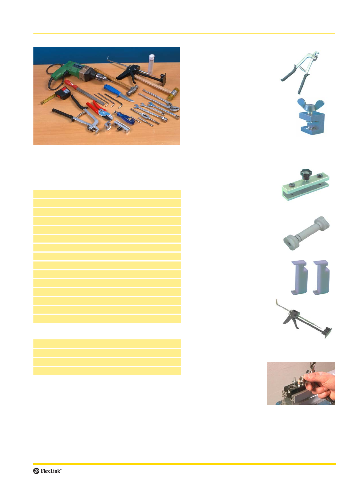
Tools
General tools
To assemble a FlexLink conveyor, you will need most of
the tools listed on the following pages. Not all are essential, but they will make your assembly work easier and
more efficicient.
Hand tools
10 and 13 mm box wrench
Cutters (for cutting slide rail)
Set of metric Allen keys
Roller thread fluteless tap and tap wrench (M6 and M8)
Countersink bit
Tape measure
In addition, the tools listed below can be useful:
Files
Socket wrench
Screw-driver
Pliers
Knife (for cutting off plastic screw heads)
Soft faced hammer
Clamp (for chain installation)
Level
Power tools
Cross-cut circular saw for aluminium
Hand drill
Drill bit (for fixing of slide rail):
XS: ∅3,2 mm, XL/XM/XH/XK: ∅4,2 mm
FlexLink tools
Rivet crimping pliers
XS (∅ 3 mm):
3924776
XL/XM/XH (∅ 4 mm):
3925800
Rivet crimping clamp
XS (∅ 3 mm):
3924770
XL/XM/XH (∅ 4 mm):
3923005
The riveting tools have replaceable pads. By replacing the pads
you can use the same riveting
tool for 3 mm and 4 mm rivets.
Drill fixture for installation of
slide rail
XS (∅ 3,2 mm):
3924774
XL/XM/XH/XK (∅ 4,2 mm):
3920500
Mounting tool for slide rail
XS/XL: XLMR 140
XM: XMMR 140
XH: XHMR 200
XK: XKMR 200
Mounting toolkit for guide rail (XK)
3926757
Each kit is delivered with two tools.
Pin insertion tool for chain
XS/XL: XLMJ 4
XM: XMMJ 6
XH: XHMJ 6
XK: XKMJ 8
Guide rail bending machine
3922963 (not shown)
Drill fixture for fastener yokes
XCAD 18
To drill for fastener yokes
(page 17–18), the 10 mm
drill insert has to be
removed. The drill insert is
secured by a locking screw.
With the stop tongue down, the fixture is inserted into
the T-slot of the beam until stop, and then locked. The
hole will be drilled 22 mm from the beam end and centered by the fixture.
Introduction 3
Page 4
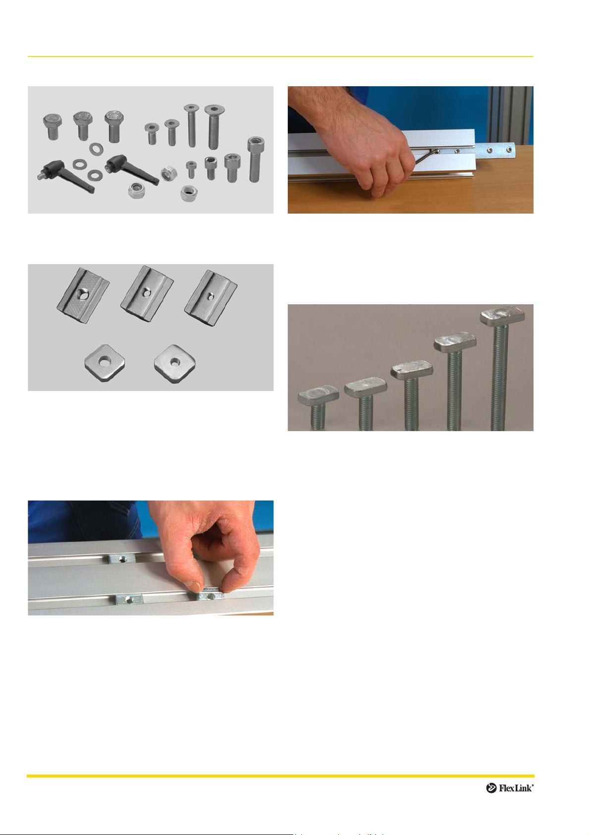
Fasteners
1. Standard screws, nuts, washers
M6S, MC6S, MF6S, M6M, BRB 8,4×16, XLAL
2. Slot nuts and square nuts
3. Connecting strips
X..CJ
Connecting strips are used for joining beams together,
end to end. Use Allen key and set screws when attaching
the connecting strip to the beam.
4. T-bolts
XCAN, XLAQ
Square nuts can be used in support beams and small
beams instead of XCAN nuts, but they can also be used
in conveyor beams as opposed to XCAN nuts. They do
not stay in place in vertical positions and have to be
inserted from the beam end.
When using XLAQ square nuts, remember to put in a
sufficient number before completing the assembly.
XCAN
On the support beam, the slot nut can be entered into the
T-slot from the beam side. It will stay in position in vertical
T-slots because of a thin leaf spring.
For small beams (e.g. XCBB ..×24×44), the nut must
be entered from the beam end because of the design of
those beams.
XLAT
T-bolts can be entered from the beam side, and when
turned 90° they will stay in place after tightening with nuts
(XLAN 8) and washers (BRB 8,4×16). The indication
groove in the T-bolt should be at 90° to the conveyor Tslot.
T-bolts are used when attaching support brackets,
guide rails and drip trays to the conveyor beam. Do not
use T-bolts with support beams!
IMPORTANT
Slot nuts can not be used with conveyor beams. (This
does not apply to the XK conveyor system.)
4 Introduction
Page 5

Cutting FlexLink beams
Beam lengths
If you have ordered 3 m or 6 m beams, they will need to
be cut into suitable lengths before assembly. Study your
drawing to determine the beam lengths that are required.
The FlexLink catalogue 5147, chapter CS, contains a formula for calculation of cutting lengths for support beams.
Saw requirements
The circular cross-cut saw for aluminium must have a
higher speed than when cutting steel, and a carbide tip
blade adapted for aluminium products in order to give a
nice and clean cut.
The saw should have the ability of cutting the largest
profile in one single cutting action.
Working site
You should use a special area for cutting beams in order
to keep the assembly area clean.
Quality of cut
If burrs are evident, they must be removed prior to
assembly.
Make sure the cut is straight for proper assembly.
SAFETY
All safety precautions issued by the cutting saw manufacturer should be followed at all times.
Introduction 5
Page 6
Assembly
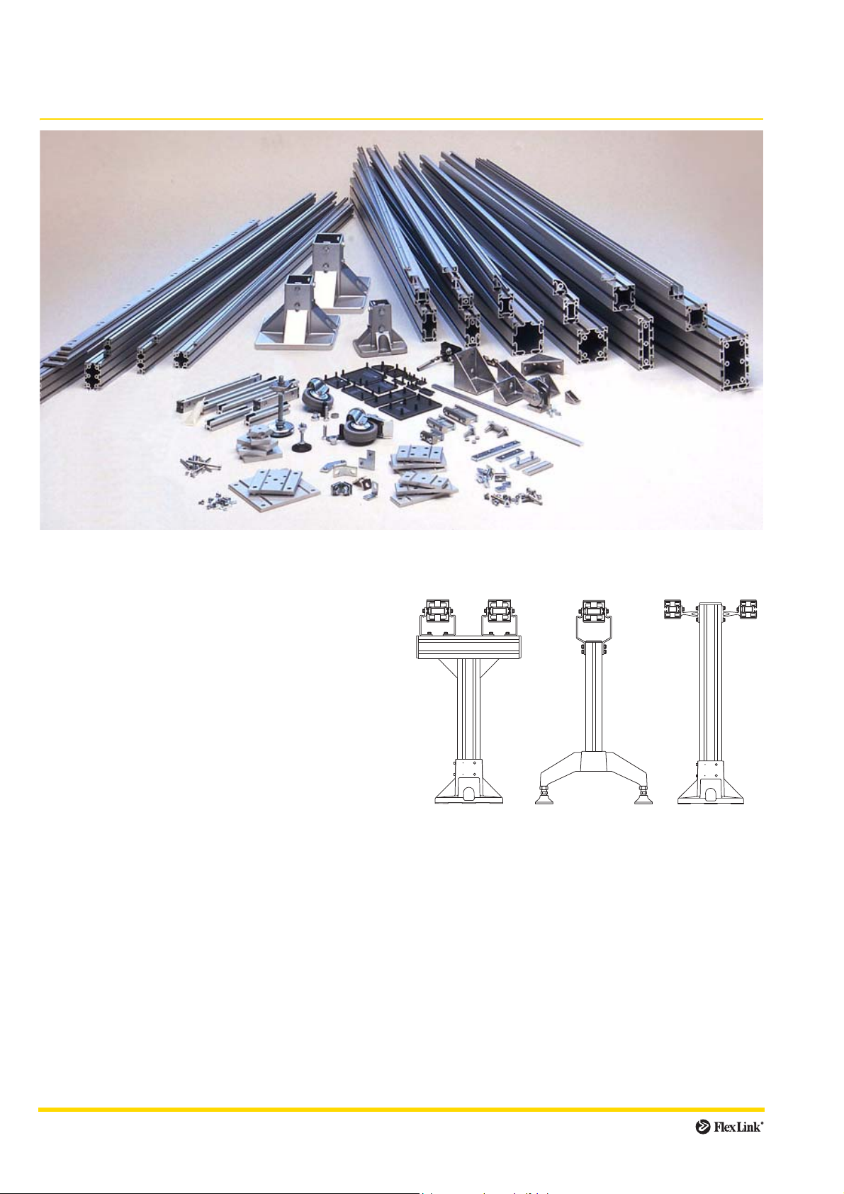
Introduction
Component groups
The basic FlexLink conveyor structure consists of five
component groups:
• support structure
• conveyor beams, straight sections and bends
• drive and idler units
•chain
• other accessories (guide rail, drip trays etc.)
The first step in the assembly process is to assemble the
support structure, which consists of feet, support beams
and beam connectors. Most conveyor support designs
are based on vertical support beams combined, if necessary, with horizontal support beams. There are also a
number of different feet and beam connectors, so check
which ones are used in your application. Some examples
are shown below.
IMPORTANT
You must work in accordance with your layout, and make
sure that the conveyor is supported at regular intervals
not exceeding 3 m.
6 Assembly
Page 7
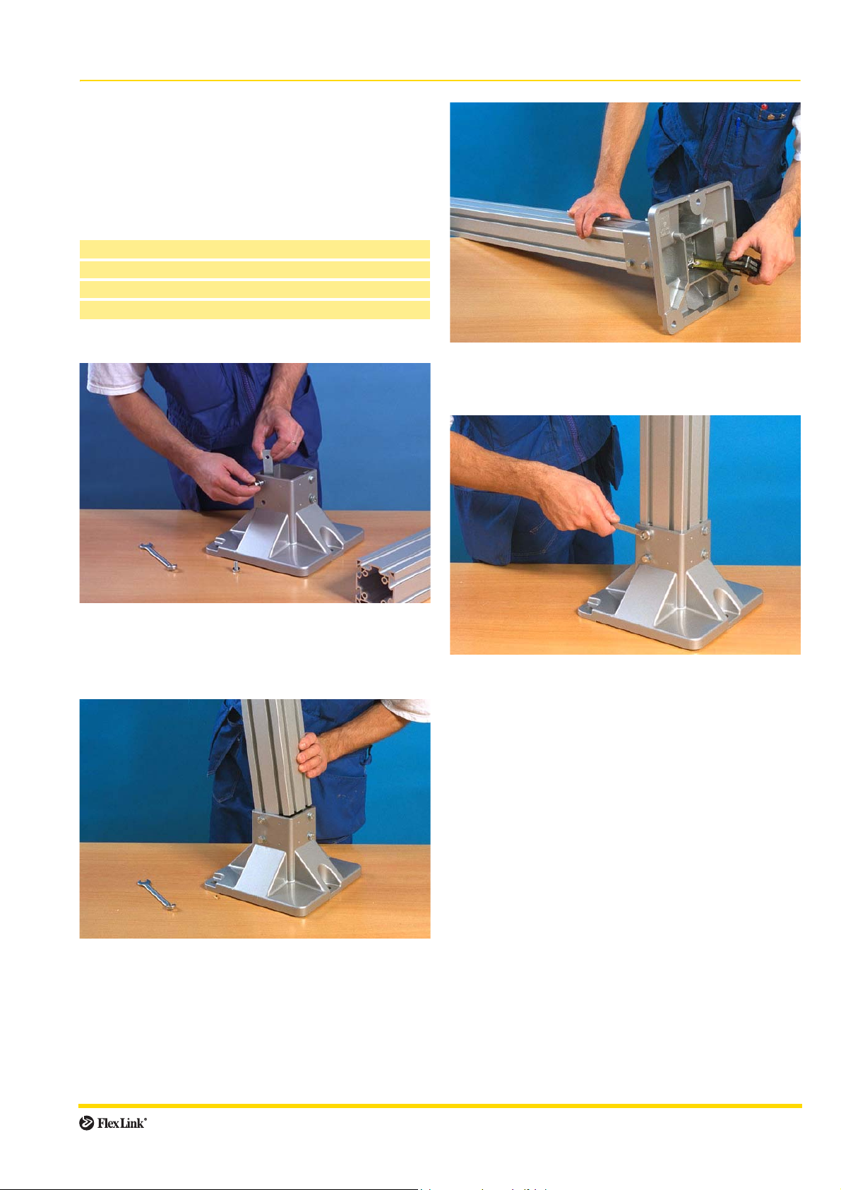
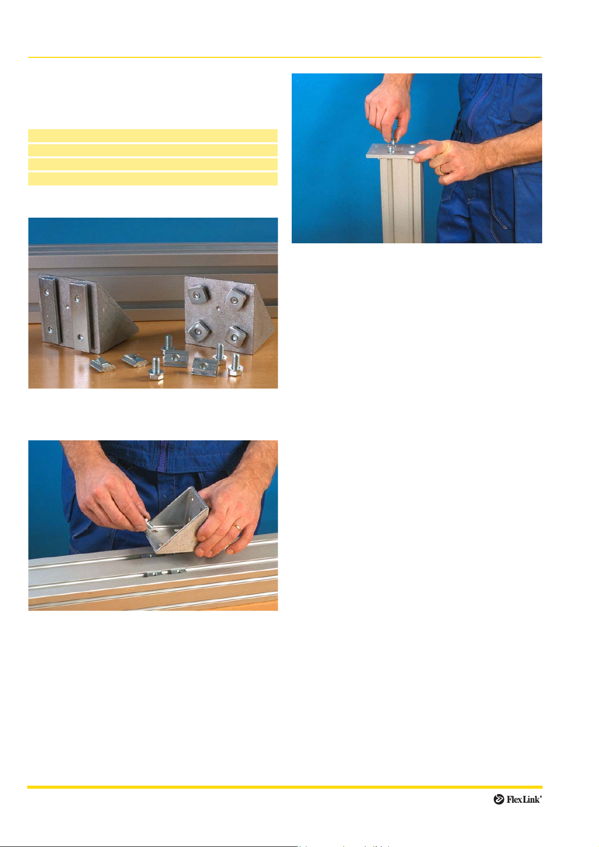
Feet
Introduction
Feet are attached to the support beams, and come in a
number of configurations. Follow the mounting instructions for the type of foot used in your application.
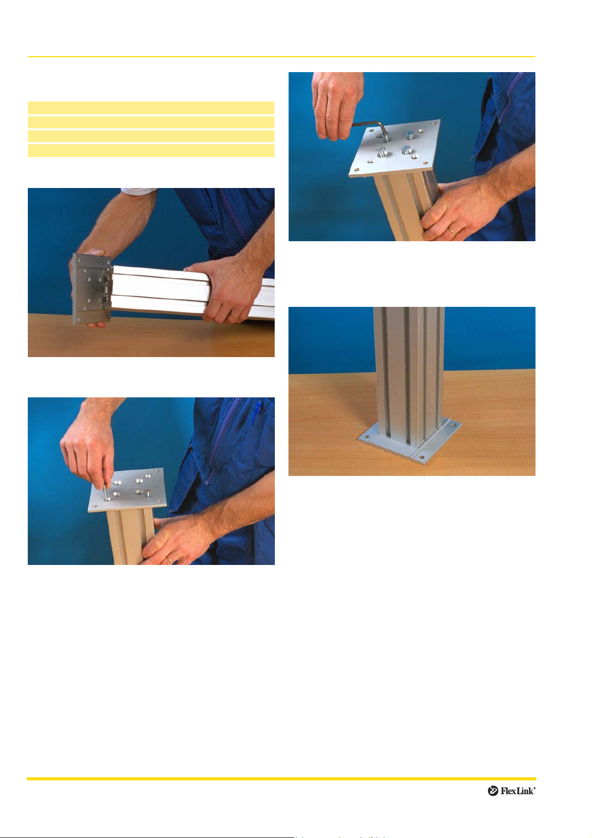
Mounting feet
XCFF:
Box wrench 13 mm
Connecting strips (included
Hex head screws (included) M6S 8×16
Washers (included) BRB 8,4×16
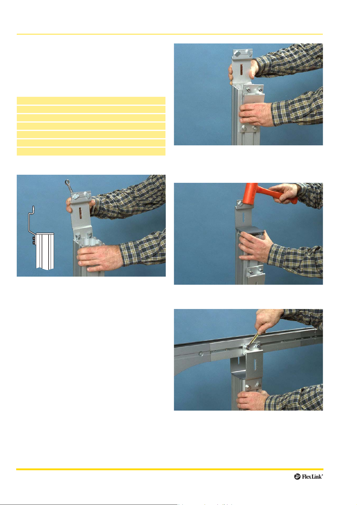
Mounting
1 Insert hex head screws and washers into the holes on
the side of the foot.
Use the screws to fasten connecting strips to the inner
side of the foot. Tighten loosely.
:
3 Raise the beam from the bottom of the foot approxi-
mately 50 mm, to allow for height adjustment later in
the assembly.
4 Tighten the screws using a wrench.
2 Slide the connecting strips into the structural beam T-
slots.
Assembly 7
Page 8
Feet (continued)
Deburring and threading beam ends
Before mounting foot plate XCFB 88/44 F, end plate
XCFE and mounting plate XCFB, the holes in the beam
cross-section must be deburred and threaded.
Countersink
Roller thread fluteless tap M6/M8
Mounting:
1 Deburr the holes using a countersink.
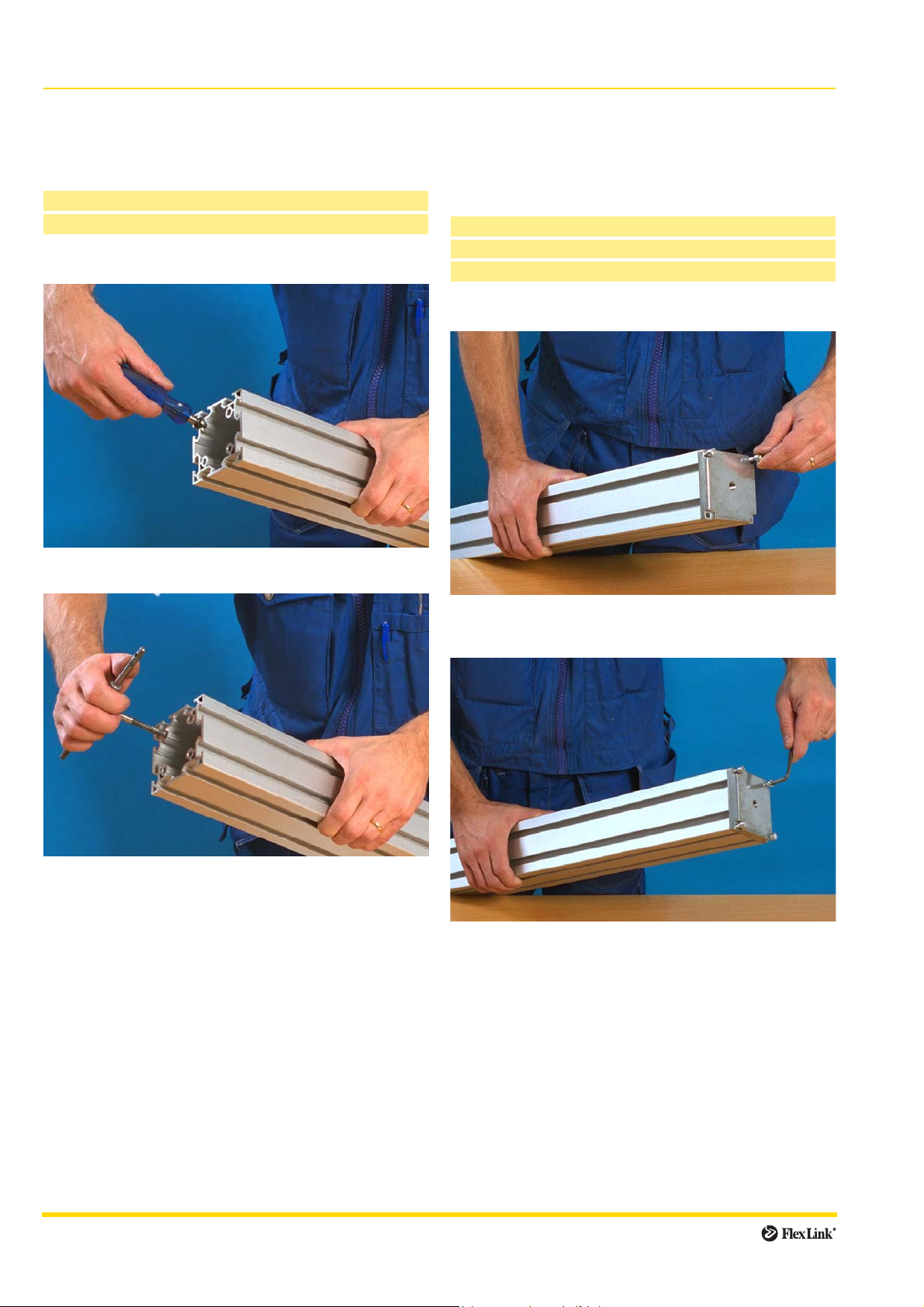
Attaching feet using end plates
XCFE
End plates are used as attachment for adjusting feet and
castors, and are screwed onto the support beam ends
before the actual foot is mounted.
Countersink
Roller thread fluteless tap M6/M8
Allen key 5 mm
Mounting:
2 Thread the holes using a 6 mm or 8 mm roller thread
fluteless tap, depending on beam and component
type.
1 Attach the end plate to the beam by inserting four hex
socket head screws into the holes on the end plate.
2 Tighten the screws using an Allen key.
8 Assembly
Page 9
Feet (continued)
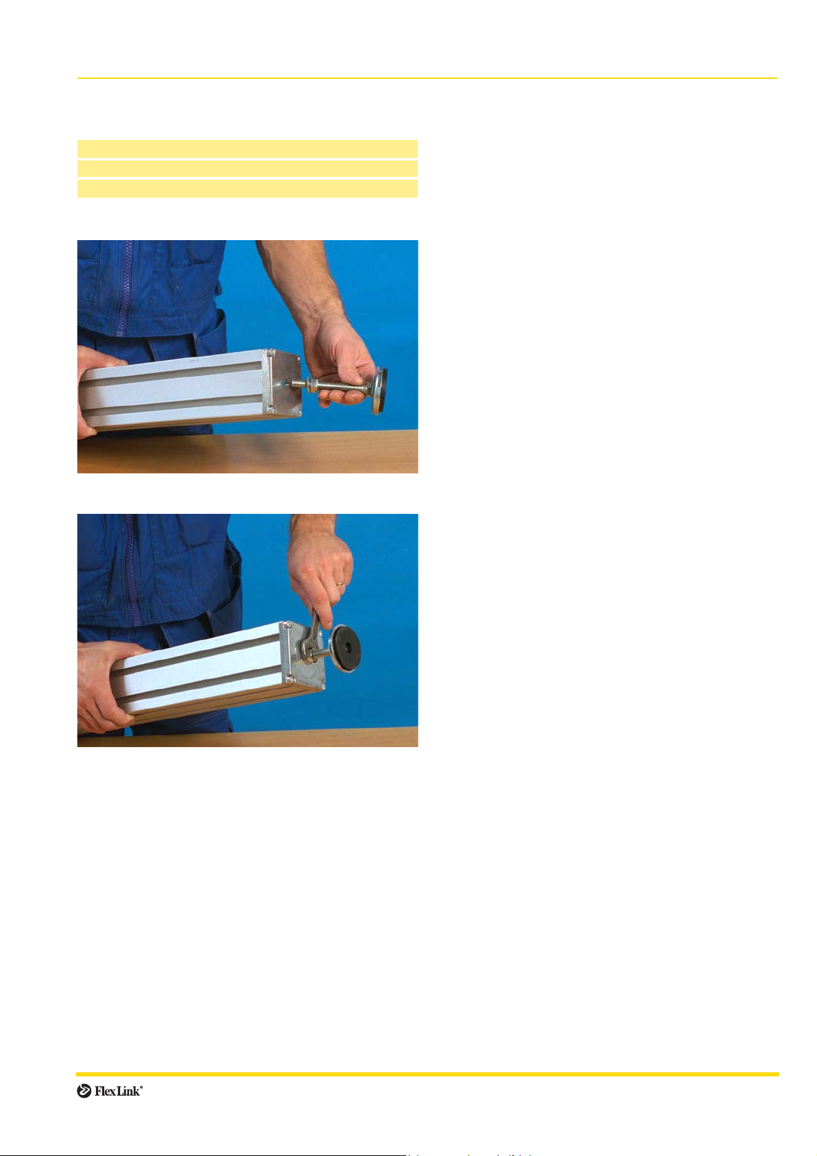
Mounting adjusting feet
XCFS 12×68
Wrench 19 mm
Nut (included) M12
Washer (included) For M12 screw
Mounting:
1 Screw the foot onto the XCFE end plate.
2 Tighten the nut using a wrench.
XLFS 8
Foot XLFS 8 can be mounted directly onto beams XCBM/
XCBR 44 or directly into any T-slot.
Connection to beam XCBM/XCBR 44:
1 Attach an end plate to the beam end.
2 Screw the foot onto the end plate and tighten with nut.
Connection to structural beam T-slot:
1 Insert a slot nut into the structural beam T-slot.
2 Screw the foot onto the beam and tighten with nut.
Assembly 9
Page 10
Feet (continued)
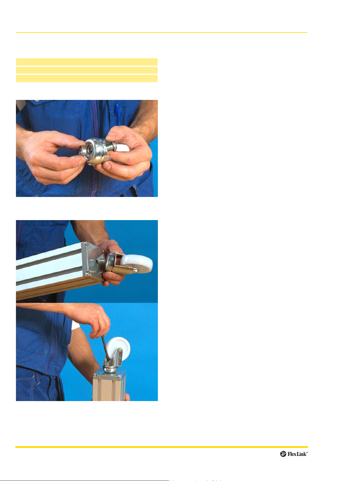
Mounting castors onto end plate
XCAG 80
Allen key 5 mm
Screw (included) K6S 12×25
Washer (included) For M12 screw
Mounting:
1 Insert screw (K6S 12×25) into the screw hole located
on the castor yoke. Add washer.
2 Screw the castor onto the XCFE mounting plate using
an Allen key.
10 Assembly
Page 11
Feet (continued)
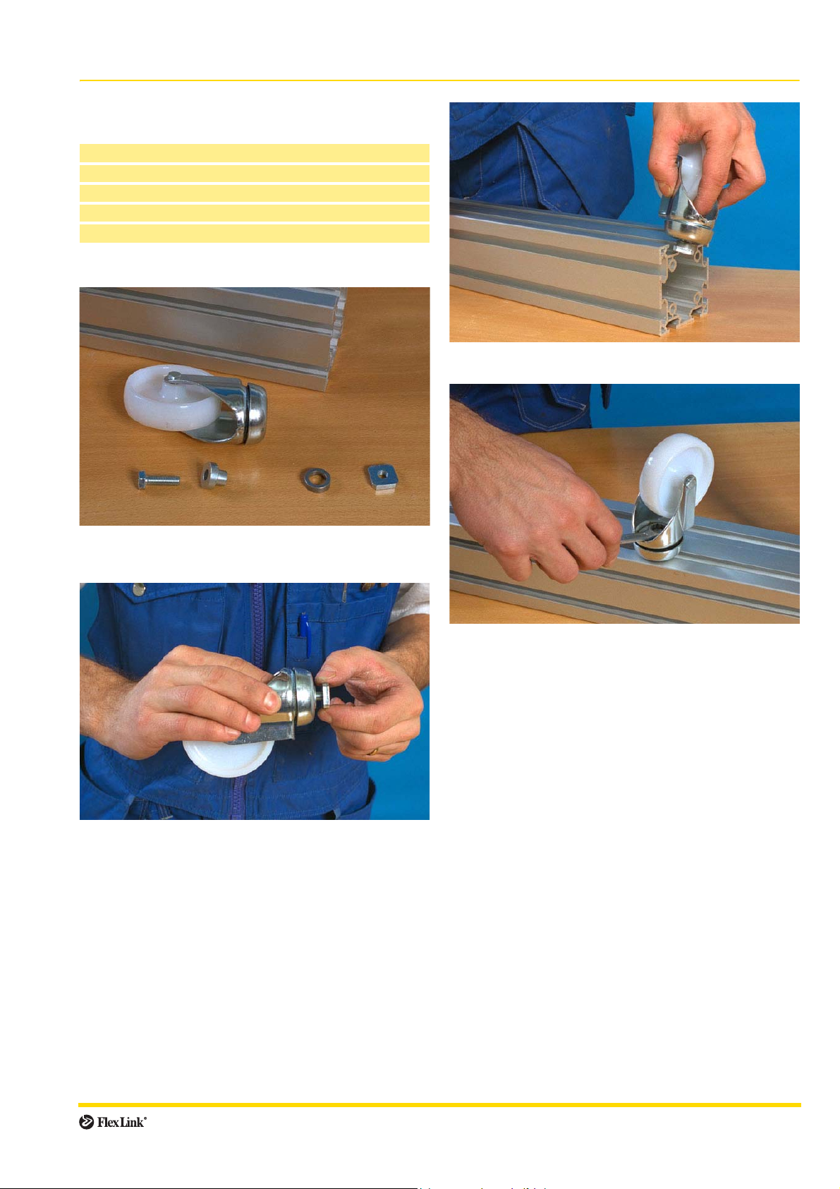
Mounting castors to structural beam T-slot:
XCAG 80
Box wrench 13 mm
Screw (included) M6S 8×25
Filling washer (included) 3905065
Washer (included) BRB 8,4×16
Slot nut (included) XLAQ 8
Mounting:
3 Slide the foot into the structural beam T-slot.
1 The picture shows the mounting order for castor fas-
teners.
2 Insert screw and filling washer into the screw hole
located on the castor yoke. Add washer and slot nut.
4 Screw the castor onto the beam using a wrench.
Assembly 11
Page 12
Feet (continued)
Mounting foot plates
XCFB...F
Countersink
Roller thread fluteless tap M8
Allen key 5 mm
Hex socket head screws MF6S 8×30
Mounting:
b) For the XCBM 88×88 beam, you can also use four
M8 screws at the centre of the plate.
For the XCBM 44×44 beam, you can also use one M8
screw at the centre of the plate.
1 Deburr and thread beam ends before mounting the
foot plate. (See page 8)
2 a) Mount the foot plate onto an XCBL 88×88 mm light
support beam using four M6 screws at the corners of
the plate.
Mount the foot plate onto an XCBL 44×44 mm light
support beam using four M6 screws at the corners of
the beam.
12 Assembly
Page 13
Feet (continued)
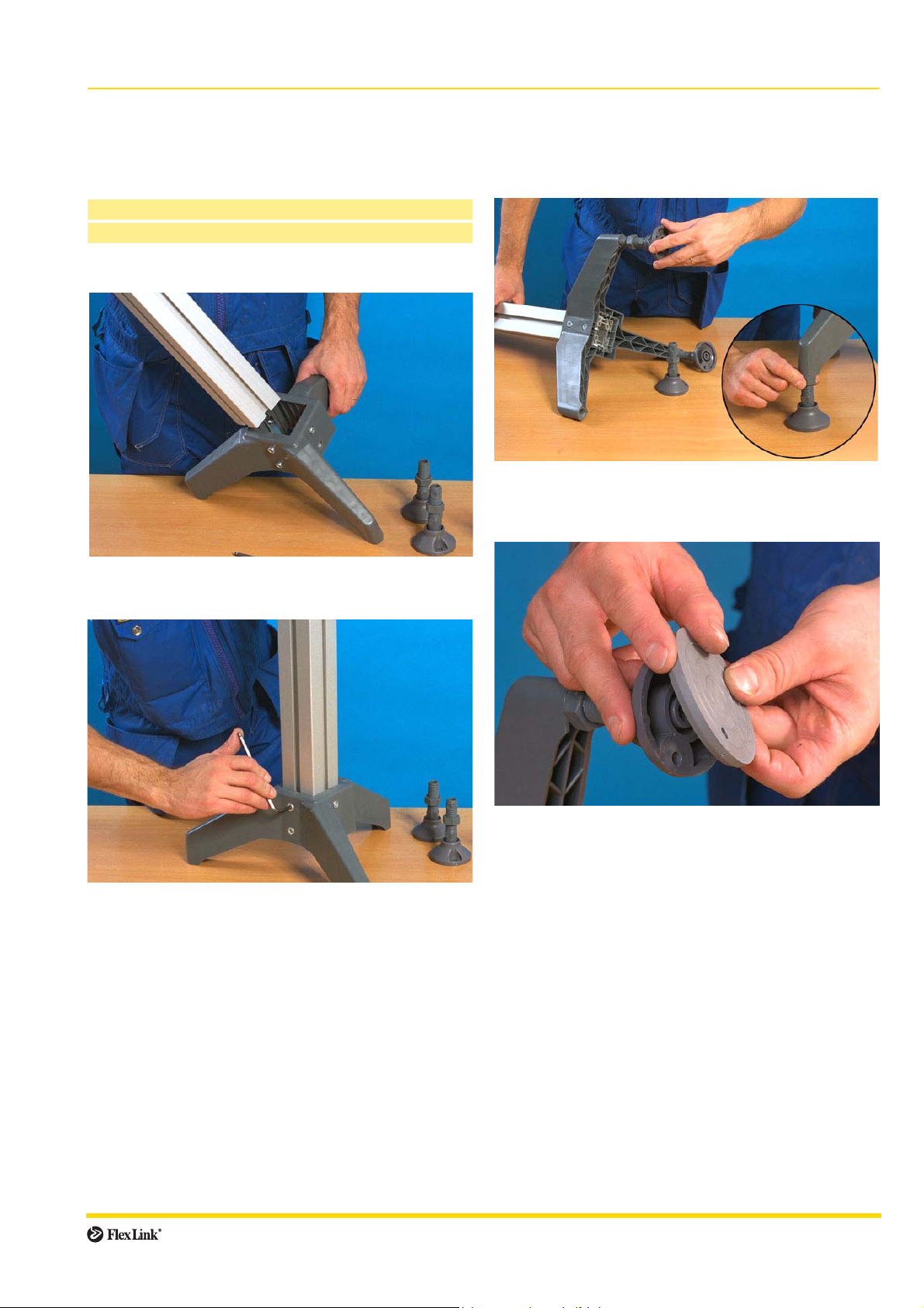
Mounting polyamide feet
XEFG
Polyamide feet are used with 64 mm structural beams
only.
Allen key 5 mm
Hex socket head screws (included) MC6S 8×16
Mounting:
Adjusting mounts and vibration absorbers
XLFS 20 P, XLFJ 69
Mounting:
1 Adjusting mounts are screwed onto the bottom of the
foot and fastened with the locking nuts that are
included.
1 Mount the foot onto the beam end by sliding the foot
compression clamps into the beam T-slot.
2 Tighten the screws. The recommended tightening
torque is 15 Nm.
2 Vibration absorbers are snapped on to the bottom of
the adjusting mounts.
Assembly 13
Page 14
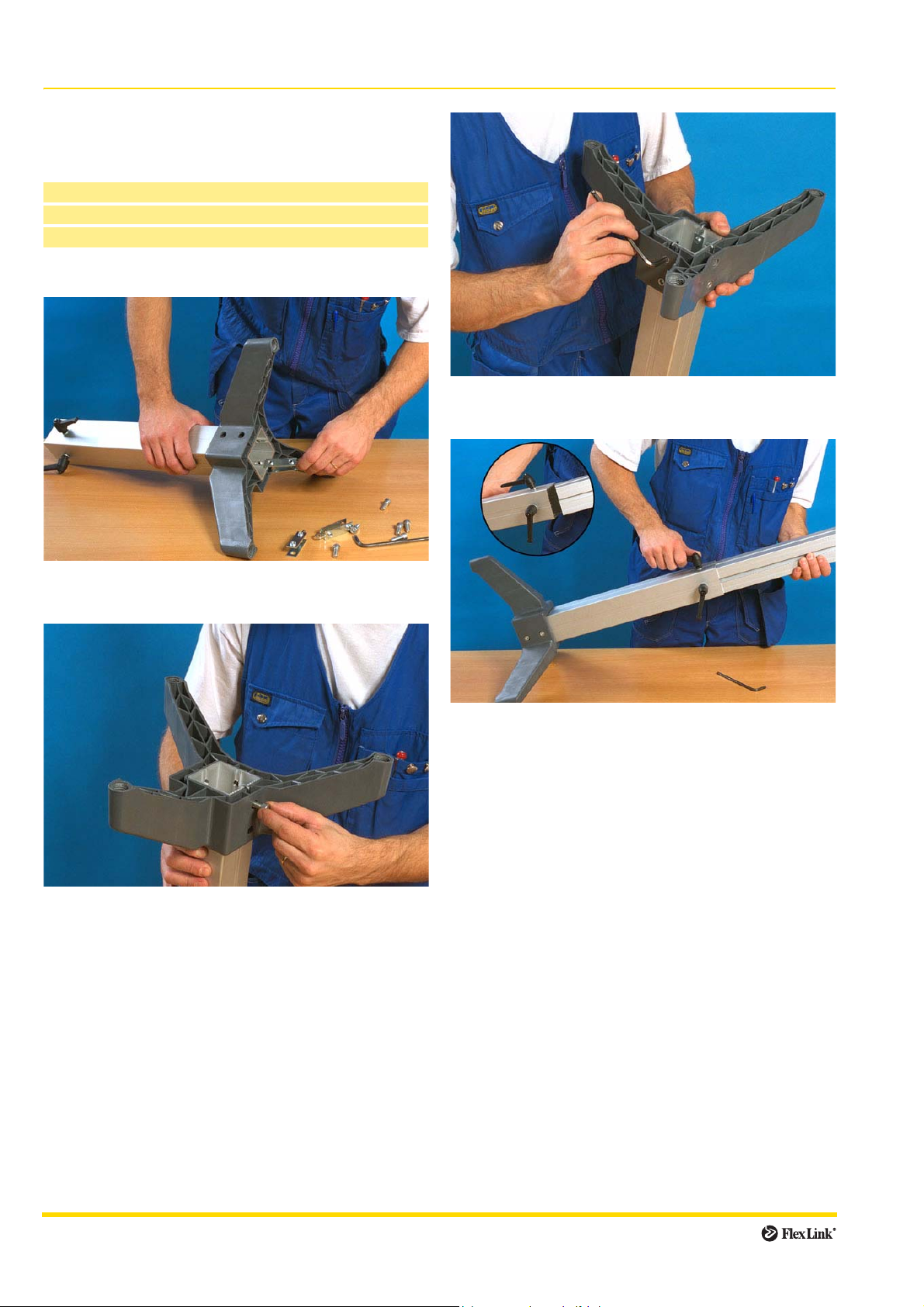
Feet (continued)
Height adjustment assembly
XEFU 500
Used with XEFG 70 T foot only.
Allen key 5 mm
Lock brackets (included) 3903139
Hex socket head screws (included) MC6S 8×20
Mounting:
3 Tighten screws using an Allen key. The recom-
mended tightening torque is 15 Nm.
1 Attach the height adjustment assembly to the foot by
sliding the lock brackets into the slots on the beam.
2 Insert screws.
4 Insert the beam into the adjustment assembly and set
it at the required height.
Fasten the beam using the adjustment assembly lock-
ing levers.
14 Assembly
Page 15
Beam connectors
Introduction
Structural beams can be connected to each other in a
number of ways. Three different methods are described
on the following pages.
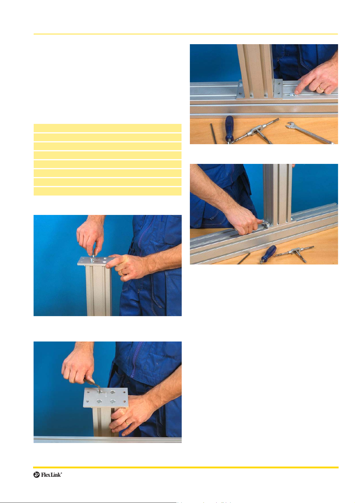
Connecting beams using mounting plates
XCFB
Deburr and thread beam ends before assembly. (See
page 8):
Countersink
Roller thread fluteless tap M6
Box wrench 10 mm
Allen key 5 mm
Hex socket head screws MF6S 8×30
Hex head screws M6S 8×16
Washers BRB 8,4×16
Slot nuts M8 thread
Mounting:
1
1
3 Insert slot nuts into the T-slots of the transverse beam.
1
1 Attach a mounting plate to the beam end using
MF6S 8×30 hex socket head screws and washers.
1
4 Screw the mounting plate onto the side of the trans-
verse beam using hex head screws M6S 8×16.
2 Tighten the screws using an Allen key.
Assembly 15
Page 16
Beam connectors (continued)
Connecting beams using angle brackets
XMFA, XLFA
Angle brackets are used to connect beams end-to-side or
side-to-side.
Box wrench 10 mm
Screws M6S 8×16
Slot nuts M8 thread
Washers BRB 8,4×16
Mounting:
3 Mount the angle bracket to the transverse beam in the
same manner. Tighten all screws.
1 Three different kinds of slot nuts can be used when
mounting angle brackets: connecting strip
XLCJ 5×76, square nut XLAQ 8 or slot nut XCAN 8.
2 Insert the required amount of slot nuts into the struc-
tural beam T-slot. Mount the angle bracket using
screws and washers.
16 Assembly
Page 17
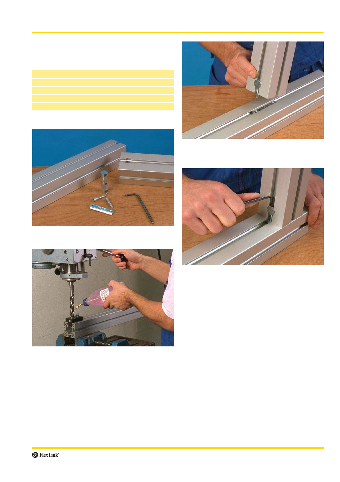
Beam connectors (continued)
Connecting beams using fastener yokes 1
XCAF
Method 1 – beam end against beam side
Drill ∅ 18,25
Drill fixture XCAD 18
Allen key 5 mm
Hex socket head screws (included) MC6S
Slot nut (included)
Mounting:
3 Place a fastener yoke in the hole and insert one 6×30
hex head screw on each side. Insert a slot nut into the
transverse beam.
1 The fastener yokes shown in the pictures are for
64 mm structural beams.
2 Use an XCAD 18 drill fixture to drill a 18,25 mm hole
through the end of the beam. While drilling in aluminium, be sure to lubricate the drill bit with methylated
spirits.
4 Tighten the screws using an Allen key. (The recom-
mended tightening torque for a lubricated joint is
10 Nm.)
Assembly 17
Page 18
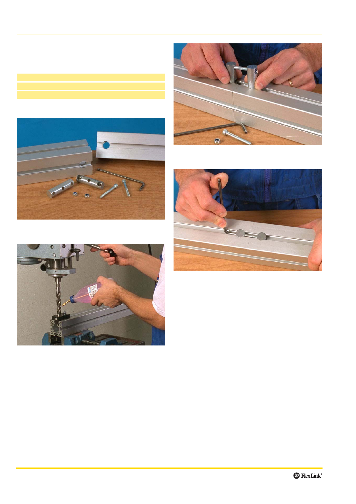
Beam connectors (continued)
Connecting beams using fastener yokes 2
XCAF
Method 2 – beam end against beam end
Allen key 5 mm
Screws MC6S 6×50
Nuts XLAN 6
Mounting:
3 Connect the two fastener yokes with one screw and
nut. Place the yokes in the holes of the beams.
1 Two fastener yokes are required when mounting
beam end against beam end.
2 Use an XCAD 18 drill fixture to drill a 18,25 mm hole
through the end of the beam. While drilling in aluminium, be sure to lubricate the drill bit with methylated
spirits.
4 Connect the yokes on the other side of the beam.
Tighten both screws.
18 Assembly
Page 19
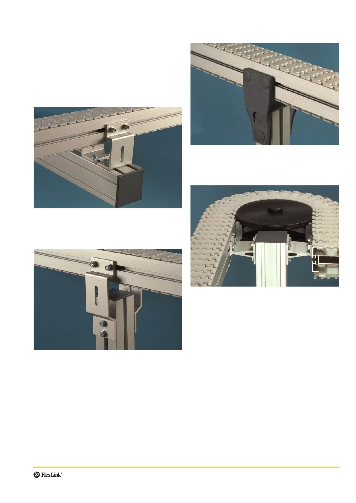
Conveyor beams
Introduction
Conveyor beams are mounted on to the support structure
by means of support brackets. There are three different
types of conveyor beam support brackets. They all serve
the same purpose but are connected to the structural
beams in different ways.
Beam support brackets
Type B: X..CS.. (polyamide)
When attaching plastic beam support brackets, always
use a flat washer between nut and bracket. The nuts can
be covered by plastic plugs.
Type A: XLCT..
Type A brackets are used with crossing 64 mm or 88 mm
support beams. These brackets can also be used as drip
tray connectors
Type B: X..CS.. (aluminium)
Type B brackets are used with vertical support beams
and are made from either aluminium or polyamide. The
aluminium types can be used instead of drip tray brackets. (See example on page 48)
Type C: XLCU 73
Type C brackets are used for connecting two parallel conveyor beams to an 88 mm vertical support beam.
Assembly 19
Page 20
Conveyor beams (continued)
Mounting conveyor beam support brackets
X..CT, X..CU, X..CS
Start by erecting structural beams and attach one conveyor beam support bracket to each beam.
It may be easier not to mount the second bracket until
slide rail has been mounted and, if using catenary or end
drive unit, the chain has been installed.
Box wrench 13 mm
Hex head screws M6S 8×16
Slot nuts XCAN 8
Washers BRB 8,4×16
T-bolts XLAT 17
Nuts XLAN 8
Washers BRB 8,4×16
Mounting
2 Insert the slot nuts of the second support bracket into
the support beam T-slots. Slide the bracket down so
that it does not protrude above the cross-section of
the beam.
1 Attach screws, nuts and washers to the support
bracket before mounting. (Screws and slot nuts are
support beam fasteners, T-bolts and nuts are con-
veyor beam fasteners.)
Slide the slot nuts of one support bracket into the sup-
port beam T-slots. Tighten the screws. Make sure that
the support bracket is aligned with the beam cross-
section as shown in the drawing.
3 Use a soft hammer to mount an end cap on to the
support beam.
4 Mount the first support bracket to the conveyor beam.
Pull the second bracket up and insert the T-bolts into
the conveyor beam T-slot. Tighten the nuts.
20 Assembly
Page 21
Conveyor beams (continued)
Assembling conveyor beams
The next step is to connect conveyor beams – straight
sections and bends – to each other. Connect all conveyor
beams according to the instructions below.
Straight sections X..CB
Wheel bends X..BH
Horizontal plain bends X..BP
Vertical plain bends X..BV
Allen key 4 mm
Connecting strips with set screws XLCJ
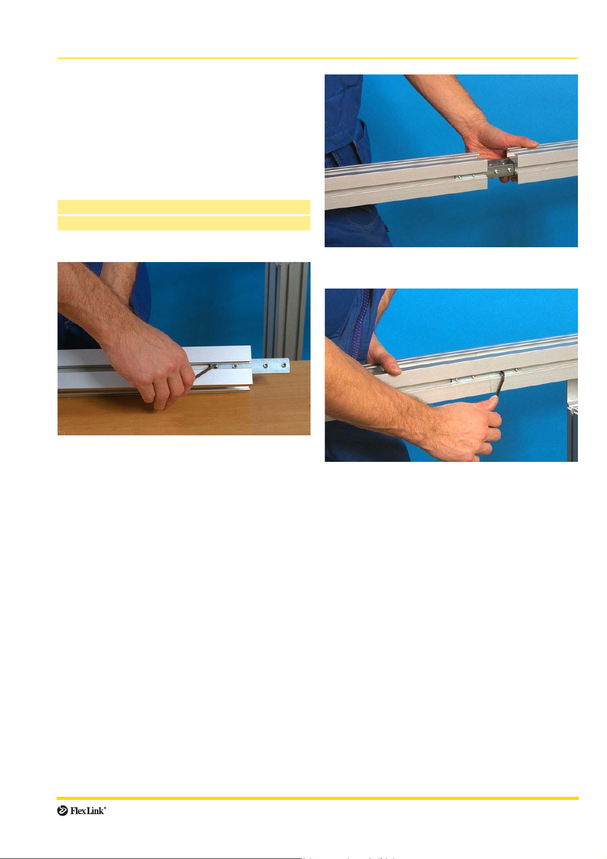
Mounting:
1 Connect two conveyor beam ends by inserting con-
necting strips into the beam T-slots. Use two connecting strips per beam joint.
2 Make sure that the set screws do not prevent the con-
nection strips from sliding into place.
3 Tighten the set screws using an Allen key.
Assemble the entire conveyor beam structure in the
same way. If the conveyor beam is too long to mount onto
the support structure in one continuous length, assemble
shorter lengths and connect them to each other once fastened to the support beams.
Assembly 21
Page 22

Drive units
Introduction
Step three is to mount drive and idler units to the frame
structure. All drive and idler units come with connecting
strips included. Attach them to the conveyor beam using
an Allen key and the set screws that are included.
Drive units can be attached to supports of various
kinds; check your drawing to see how your conveyor is
designed.
It should be remembered that conveyor chains should
always be pulled, not pushed, by the drive unit.
Mounting of end drive unit
X..EB 5 H
Allen key 4 mm
Mounting:
1 Mount the end drive unit on to the end of the con-
veyor:
Release the four set screws that are inserted into the
drive unit connecting strips. Insert the connecting
strips into the T-slot of the beam you want attached to
the end drive unit.
Make sure that the set screws do not prevent the connecting strips from sliding into place.
Caution:
When installing a drive unit, ensure that
the slip clutch is fully released.
The conveyor chain catenary of
end drive units must be maintained during the system lifetime.
When the conveyor chain is visible through the slot in the sideplate, it must be shortened.
2 Tighten the set screws using an Allen key.
22 Assembly
Page 23

Drive units (continued)
Intermediate drive unit
X..ER 5 H
Intermediate drive units can be installed anywhere along
the conveyor, although it should be mounted as close to
the end of the conveyor as possible.
Attach the drive unit to the conveyor beam using the
connecting strips that are included. (See mounting
instructions for end drive unit, page 22)
Caution:
When installing a drive unit, ensure that
the slip clutch is fully released.
The area near the guides for the return
loop of the chain should not be accessible
during conveyor operation.
There must be no conveyor chain catenary when
using intermediate drive units.
Adjustment of the position of the bridge area may be necessary, depending on weight and shape of the products
that are being transported. Adjust the bridge by loosening the two screws on the side below the bridge, and then
loosening the four remaining screws. Adjust the bridge
position and tighten all screws.
Caution:
When installing a drive unit, ensure that
the slip clutch is fully released.
The bridge area where the chain
goes down should not be accessible during conveyor operation.
The conveyor chain slack of catenary drive units must be main-
tained during the system lifetime.
When the conveyor chain is visible through the slot
in the plastic cover, it must be shortened.
Horizontal bend drive unit
X..EW 180/5 H
Catenary drive unit
X..EC 5 H
Catenary drive units are used in “endless chain” conveyor systems with no return chain.
Catenary drive units can be installed anywhere along
the conveyor length.
Attach the drive unit to the conveyor beam using the
connecting strips that are included. (See mounting
instructions for end drive unit, page 22)
The horizontal bend drive unit is used for endless conveyors with no return chain.
Attach the drive unit to the conveyor beam using the
connecting strips that are included. (See mounting
instructions for end drive unit, page 22)
Caution:
When installing a drive unit, ensure that
the slip clutch is fully released.
There must be no conveyor chain catenary
when using horizontal bend drive units.
The drive wheel should not be accessible
during conveyor operation.
Assembly 23
Page 24

Drive units (continued)
Double drive unit
X..EB 5 HD
Idler units
C/C 55 (XS), 66 (XL), 86 (XM), 106 (XH) and 106 (XK)
drive units are supplied with four connecting strips. However, since space is limited, only the two outer connecting
strips can be used for beam attachment. (See mounting
instructions for end drive unit, page 22)
C/C 90–350 (XS), 110–350 (XL), 130–350 (XM), 150–
350 (XH) and 150–350 (XK) drive units are connected to
the beam with four connecting strips. (See mounting
instructions for end drive unit, page 22)
Caution:
Ensure that the shaft is not accessible during conveyor operation.
When installing a drive unit,
ensure that the slip clutch is fully
released.
The conveyor chain catenary of
double drive units must be main-
tained during the system lifetime.
When the conveyor chain is visible through the slot
in the side-plate, it must be shortened.
Introduction
Idler units are used to guide the conveyor chain into the
return side of the conveyor. Connecting strips are already
attached to the unit.
Idler end unit
X..EJ
Idler bend unit
X..EK
The 90° idler bend can only be used with a return chain
together with the XL conveyor system.
24 Assembly
Page 25

Idler units (continued)
Mounting idler units
Allen key 4 mm
Mounting:
1 Insert the idler unit connecting strips into the
T-slots of the beam end.
Mounting idler end protective cover
Allen key
Mounting:
1 Remove three of the five M5×10 screws that holds the
idler end side plate in position.
2 Secure the idler unit to the beam using an Allen key to
tighten the set screws.
Caution:
The opening between the links when they
turn around the idler could be a risk. Idler
ends should not be accessible during conveyor operation. (For mounting of idler end
protective cover, see next page.)
Assembly 25
2 Slide the cover onto the idler end unit.
3 Insert and tighten the three M5 screws that are deliv-
ered with the cover
Page 26

Slide rail and support rail
Introduction
XLCR
The slide rail is attached to the sides of the conveyor
beam to reduce chain friction where the chain would
otherwise be in direct contact with the beam profile. It is
very important that the slide rail is installed properly, so
that the chain can run without disruption.
When the conveyor is to be mounted high above
ground level, it might be easier to mount the slide rail onto
a conveyor section while the conveyor beam is still on the
floor. If doing so, leave an extra end, approximately
300 mm longer than the beam, so that it can be cut off
and adjusted when the beam is finally installed.
Slide rail beam attachment
To ol s:
Slide rail installation tool
Cutting pliers
Mounting:
1 Start at an idler end unit. Separate the top and bottom
flange of the slide rail at the end of the rail and press
it into place.
3 Use the slide rail mounting tool to press the slide rail
into place. One end of the tool is used when slide rail
is mounted onto only one side of the beam, and the
other end is used when you mount slide rail onto the
second side.
4 Do not forget to mount slide rails both underneath and
on the upper side of the beam (unless top running
chain only).
2 Make sure that you mount the slide rail so that it snaps
on to the beam. The different types of slide rail do not
look alike, so check which flange should be on top.
26 Assembly
Page 27

Slide rail and support rail (continued)
Joining slide rail ends
Cutting pliers
Mounting:
1 Cut both slide rail ends in a 45° angle.
The beginning of a new slide rail section (in the direction of travel must be cut back a small angle.
2 Allow a space of approximately 10 mm between two
slide rail ends.
The arrow indicates travel direction.
3 Do not place two slide rail joints opposite each other.
Make sure there is a distance of at least
100 mm between them to make the chain run
smoother.
This does not apply to slide rail that begins by an idler
unit or after a drive unit, where joints are always parallel.
Try to let the slide rail run in as many continuous lengths
as possible, except in circumstances stated below:
• It is recommended to use short slide rails (2–3 m)
where chemicals may have an effect on the slide rail
composition.
• It is important to cut the slide rail and allow for elongation in high load areas. Cutting is required in wheel
bends (see following page), by idler units and where
the conveyor will be heavily loaded, especially by the
drive units. This prevents the slide rail from stretching
out and entering into the drive unit, which may block
the chain.
• Never join slide rail in horizontal or vertical bends,
since forces are higher on the slide rail in these sections. Instead, place the joint before the bend.
• Avoid joining slide rails on top of conveyor beam
joints.
Assembly 27
Page 28

Slide rail and support rail (continued)
Mounting slide rail in wheel bends
Cutting pliers
Before wheel bend:
Mounting:
1 Cut the slide rail end in a 45° angle.
After wheel bend:
Mounting:
1 Cut the slide rail in a 45° angle with a short back cut.
The slide rail must be longer than the conveyor beam
itself, and there should be a 2 mm distance between
the slide rail and the wheel of the bend.
2 The slide rail must be longer than the conveyor beam
itself, and there should be a 10 mm distance between
the slide rail and the wheel of the bend.
Make sure that the end of the slide rail is not bent up
or down.
2 In the outer bend, make sure that the slide rail is prop-
Horizontal plain bends
In plain bends with small radii, the slide rail for the inner
bend should be cut so that it is only 10 mm wide in the
bend. This is to prevent an uneven slide rail surface.
Stretch the rail while mounting.
Note:
28 Assembly
erly connected to the conveyor beam profile.
Plain bends with small radii should be
avoided, if at all possible. Always consult
FlexLink Systems for design assistance.
Page 29

Slide rail and support rail (continued)
Fixing slide rail to the conveyor beam
Hand drill
Drill fixture for slide rail 4,2 mm (XS: 3,2 mm)
Countersink
The beginning of each slide rail section must be fixed to
the beam, since the chain will cause the slide rail to be
pushed forward. Slide rail which moves into a wheel bend
or a drive unit can block the chain completely.
There are two different methods for fixing slide rail to
the conveyor beam: using aluminium rivets or plastic
screws. Either method can be used, but the riveting
method is more secure if the conveyor will run with high
operational speed or be heavily loaded.
Drilling slide rail
Procedure:
1 Drill two holes near the beginning of each slide rail
section. Use the drill fixture to ensure clean-cut holes
and the correct location of the holes. For drill bit
radius, see table.
The holes must be at the leading edge of the joint
piece, in the direction of travel, to hold the slide rail in
place when the conveyor is in use. Use a well-sharp-
ened drill-bit.
The arrow indicates running direction.
2 Use a countersink to deburr and countersink the
holes. Also make sure that there are no metal filings
left underneath the slide rail.
Conveyor system Drill bit diameter Rivet
XS ∅3,2 mm XLAH 3×6
XL/XM/XH ∅4,2 mm XLAH 4×6
Slide rail in conveyor beam section XLCH 5 V
When using articulated beam section XLCH 5 V, the slide
rail must be mounted across the entire beam section, and
cut off at the beginning of the following beam section.
Assembly 29
Page 30

Slide rail and support rail (continued)
Method 1: Using aluminium rivets
Rivet crimping pliers/rivet crimping clamp
Aluminium rivets
Mounting:
1 Insert rivets in the holes, using rivet crimping pliers or
a rivet crimping clamp. For type of rivet, see table on
previous page.
wrong
correct
3 Check that the rivets do not protrude over the surface
of the slide rail.
Check both top and underneath surface of slide rail for
protruding metal.
2 If working space is limited, the rivet crimping clamp
might be easier to use. The two crimping tools perform the same task, but the pliers are more efficient
and easier to use.
4 Keep a distance of approximately 30 mm between riv-
ets and idler unit. This is in case the idler unit has to
be removed after conveyor system assembly.
30 Assembly
Page 31

Slide rail and support rail (continued)
Method 2: Using plastic screws
Pliers/screwdriver
Knife
Hammer
Plastic screws XLAG 5
An alternative to aluminium rivets is to use plastic screws
XLAG 5:
Mounting:
3 Make sure the slide rail surface is smooth and that
screws do not protrude over the surface of the slide
rail. If the surface should be uneven, file the edges
smooth.
Check both top and underneath surface of slide rail for
protruding plastic or metal.
1 Press or screw the screws into the holes using a pair
of pliers or a screwdriver.
2 Cut off the screw heads by using a knife and a ham-
mer. The cut should be made away from the joint, in
the direction of chain travel.
4 Keep a distance of approximately 30 mm between
screws and idler unit. This is in case the idler unit has
to be removed after conveyor system assembly.
Assembly 31
Page 32

Slide rail and support rail (continued)
Mounting support rail in plain bends
Mounting:
1 Cut the support rail in a 45° angle. The cut should be
made at the leading edge of the rail, in the direction of
travel, to ensure a smooth entrance of the chain.
4 Drill a hole at the first end (in the direction of travel) of
the inner bend using a 4,2 mm drill bit. Leave a distance of 20 mm between the hole and the beam end.
Deburr the hole.
2 Mount the support rail on the inside of the beam pro-
file. Let the rail run along the entire bend, including the
straight sections of each end.
3 Cut the rail at the other end in a 90° angle using a
knife and a soft hammer.
5 Clamp the support rail to ensure a proper fit. Insert a
short piece of rail between the clamp and the support
rail to get a tight grip. Repeat this procedure along the
entire bend.
6 Insert a plastic XLAG 5 screw in the drilled hole and
tighten it. Make sure that the screw enters the support
rail.
32 Assembly
Page 33

Chain
Introduction
When all beams have been assembled and the slide rail
is in place, it is time to assemble and mount the chain on
to the conveyor system.
Joining chain ends
Assemble the chain by inserting the steel pin that comes
with each chain link, into the opposite end of another link.
Do this by using the FlexLink pin insertion tool.
Pliers
FlexLink chain tool
Mounting:
3 Line the FlexLink chain tool up with the pin. Slowly
depress the trigger until the pin seats.
1 Insert the plastic pivot with the slot facing outward.
2 Insert the steel pin halfway, using a pair of pliers.
Always use new steel pins and plastic pivots when
joining chain ends.
Wrong
4 Check that the chain is flexible in the joint, and that the
pin does not stick out or go through the other side.
Taking the chain apart:
1 Line the chain tool up with the pin.
2 Depress the trigger until the pin pops out.
3 Depress lever, pull insertion pin out.
4 Pull chain apart.
Assembly 33
Page 34

Chain (continued)
Mounting preparations
Procedure:
1 Remove the drive unit transmission cover.
3 Remove the side plate on the drive unit.
2 Release the slip clutch so that the drive shaft is free to
turn. (Slip clutch adjustment, see page 66)
With the slip clutch loose, make sure that the motor is
turning in the correct direction.
4 Before mounting, run a short piece of chain (0,5 m)
through the conveyor to ensure a smooth running system. If any obstructions are found, they should be
removed and the checking process repeated.
34 Assembly
Page 35

Chain (continued)
Mounting the chain
Make sure that the slip clutch is released allowing the
drive shaft to turn freely. (See previous page.)
Pin insertion tool X..MJ
Mounting:
1 Insert the chain into the underside of the drive unit.
Make sure the chain will be moving in the correct
direction, as indicated by the arrow located at the side
of all chain links.
3 Join 5 meter lengths of chain when necessary.
2 Feed the chain along the conveyor by pulling it
through the idler unit and back to the drive unit.
4 Stretch the chain and remove links if necessary, so
that the chain will exhibit some slack at the drive unit.
(Length adjustment, see page 37)
Connect the chain ends. (See page 33)
Assembly 35
Page 36

Chain (continued)
Mounting the chain using a beam section for
chain installation
X_CC 160/XKCC 200
Allen key
Pin insertion tool X..MJ
Clamp
Mounting:
3 Clamp the chain to the beam profile. Use the
FlexLink chain tool to remove a steel pin from the
chain, so that two links are separated.
1 Loosen the screws on the beam section flanges.
2 Remove the flange so that the chain becomes acces-
sible.
4 Remove excess links and use the chain tool to put the
chain back together again.
36 Assembly
Page 37

Chain (continued)
Length adjustment of the conveyor chain
End drive units, catenary drive units
1 Adjustment of the conveyor chain is carried out at the
drive end of the conveyor.
2 The transmission guard cover must be removed from
the drive unit and the slip clutch disengaged or trans-
mission chain removed. The conveyor chain should
now be free to travel within the conveyor beam profile.
3 Catenary protection plates should also be removed to
allow easy access for the conveyor chain pin insertion
tool.
4 The conveyor chain should be tensioned within the
conveyor system by pulling down the conveyor chain
at the chain catenary in the underside of the drive unit.
Clamp across the conveyor chain to trap the chain on
to the beam profile. The clamp should be placed over
the edges of the drive unit to reduce the risk of dam-
age to the aluminium profile.
5 Remove all slack links from the conveyor chain using
the pin insertion tool.
6 Rejoin the conveyor chain using a new steel pin and
plastic pivot.
7 Remove the chain clamp and replace the catenary
protection plate and transmission chain. The slip
clutch should also be reset.
8 Replace the transmission guard cover. The conveyor
is now ready for operation.
Intermediate drive units, horizontal bend drive units
1 Conveyors which have no conveyor chain catenary
should be assembled with a special section of conveyor beam (X..CC), which allows for the chain to be
easily inserted and adjusted for tension. (See previous page.)
2 Remove the lower part of this conveyor beam section
by releasing the four screws.
3 Lift the chain from this section of the beam and clamp
the conveyor chain as described above. Adjust the
chain tension as for end and catenary drive units.
In a wheel bend drive, the outer aluminium profile can be
removed by slackening the set screws in the beam connecting strips. The slide rail must be fitted to allow the
removal of this section.
1 After removal of the outer aluminium profile, the con-
veyor chain can be pulled out of the wheel bend disc.
Lift the chain upwards.
2 Remove chain links using the pin insertion tool.
3 New steel pins and plastic pivots must be used when
rejoining chain ends.
4 The tensioned chain can now be pulled back into
position on the bend guide disc, and the outer profile
put into place.
Assembly 37
Page 38

Guide rail system
Introduction
Guide rails are used to guide products being conveyed,
but also to prevent them from falling off the conveyor.
Guide rails are supported by guide rail brackets
attached to the sides of the conveyor beam. Follow the
mounting instructions for the type of bracket used in your
application.
Brackets should be placed approximately 500 to
1000 mm apart depending on type of product and if
accumulation occurs or not. If brackets are spaced at
greater distances than 1000 mm, there is a possibility
that guide rails will become deformed due to excessive
force.
Mounting fixed guide rail brackets (aluminium)
XLRB,XLRA
Box wrench 13 mm
Pliers
T-bolts XLAT 17
Nuts XLAN 8
Washers BRB 8,4×16
Spring pins XLAP 28
2 Use a pair of pliers to insert a spring pin between the
guide rail bracket and the guide rail.
Note
Do not tighten screws if angle plates are to be
attached to the conveyor. (Angle plates, see
page 46.)
Mounting:
1 Attach guide rail brackets along the conveyor, using T-
bolts and nuts. The distance between brackets should
be approximately 0,5–1,0 m.
38 Assembly
Page 39

Guide rail system (continued)
Distance pieces (spacers)
XLRD 6/XLRD 6 P
Distance pieces can be used to increase the maximum
track width, and are placed between the guide rail
bracket and the conveyor beam. For the XL conveyor
system, distance piece XLRD 6 P can also be used to
fasten angle plates. (See picture on page 46)
Longer T-bolts must be used if distance pieces are
used with guide rail brackets.
Mounting guide rail brackets (polyamide)
The adjustable guide rails, polyamide, include components for construction of a wide variety of guide rail configurations. This includes basic fixed types as well as
high and wide guide rails in various adjustable configurations.
The pictures below show one possible way to assemble guide rail brackets. The examples shown on the following page are assembled in a similar way.
Socket wrench 13 mm
Allen key 5 mm
T-bolts XLAT 17
Nuts XLAN 8
Washers BRB 8,4×16
2 Attach a guide rail clamp to the bracket. Tighten the
screw.
Mounting:
1 Fasten a guide rail bracket support to the conveyor
beam using T-bolt, nut and washer.
3 Attach the guide rail to the clamp. Tighten the screw.
Important:
Do not over-tighten screws!
Assembly 39
Page 40

Guide rail system (continued)
Application examples
Some examples of adjustable guide rail applications are
shown below:
Examples:
Distance pieces XLRD can be used to increase track
width. Use T-bolts or stud bolts when mounting the
bracket support and distance pieces to the conveyor
beam.
Pieces of XLRN spacer beam can be used to increase
track width instead of distance pieces. Do not forget to
place an XLRD spacer beam connector between the
spacer beam and the conveyor beam.
40 Assembly
Page 41

Guide rail system (continued)
Built-up guide rail brackets
Built-up guide rail brackets are made up from pieces of
small beam with T-slots on three or four sides. The beam
is cut to suitable lengths and connected to form brackets
with the desired height and width.
Special fittings are used to connect the beam pieces
to each other, to the conveyor beam and to the guide rail.
It is possible to use more than one guide rail on each
side.
There are several types of built-up guide rail brackets
(L brackets). Assembly instructions for two different types
are described on the following pages.
Allen key 5 mm
Box wrench 13 mm
Beam XCBB 3×24×34/44
Inner fitting/corner fitting XMRY 20/XMRW 20
Inner fitting XMRX 20
Guide rail bracket XLRC 20/20A
T-bolts XLAT 17
Nuts XLAN 8
Washers BRB 8,4×16
End caps XCBE 24×34/24×44
2 Attach two XMRX 20 inner fittings to the end of the L-
bracket.
Mounting:
1 a) L bracket Type 1: Use a XMRY 20 inner fitting to
connect two beam pieces. Tighten screws.
3 Mount the bracket to the conveyor beam using T-bolts,
nuts and washers.
b) L bracket Type 2: Use a XMRW 20 corner fitting to
connect two beam pieces that have been cut in a 45°
angle.
Assembly 41
Page 42

Guide rail system (continued)
Mounting guide rail bracket to L-beam:
1 a) Attach guide rail bracket XLRC 20 A using slot nut
and an Allen key.
3 Attach guide rail to the brackets using spring pins and
a pair of pliers.
b) Attach guide rail bracket XLRC 20 using a hex
head screw and slot nut.
2 Fasten end caps at the ends of all beams using a soft
faced hammer.
42 Assembly
Page 43

Guide rail system (continued)
Connecting guide rails
For connection of guide rails, you will need connecting
plugs (XLRJ 10/15) or connecting sleeves (XLRJ 100).
Mounting
Connecting plugs are pressed into two guide rail ends.
Guide rail ends
XLRE 10/15
Mounting:
Plug all guide rail ends with end plugs. Use a soft faced
hammer when inserting the plugs.
Connecting sleeves are fastened to the guide rail ends
with set screws and an Allen key.
Make sure you place the connecting sleeves on the
outer side of the guide rail.
Assembly 43
Page 44

Guide rail system (continued)
Guide rail cover
XLRT
Mounting:
To prevent products from being scratched, a plastic guide
rail cover can be snapped on to the inside of the guide rail
(15 mm guide rail only).
Guide discs/guide rails in bends
XLRG
At the inner bend of horizontal wheel bends, a plastic
guide disc can be used instead of regular guide rail.
Mounting:
1 Remove the wheel bend cap.
Make sure that all cover joints are smooth, so that products do not get caught or damaged. Do not join covers on
top of guide rail joints.
44 Assembly
2 Press the guide disc into place on top of the wheel
bend.
Page 45

Guide rail system (continued)
Bending guide rail
If the construction of your conveyor system requires customized guide rail bends, you can use the FlexLink guide
rail bending machine (3922963) to bend them according
to your own requirements:
Mounting:
3 Operate the crank to run the rail back and forth while
lowering the upper wheel step by step until the
desired radius and angle is achieved.
1 Mark the length of the rail to be bent. Leave an
approximately 200 mm straight section at each end.
2 Place the rail horizontally between the top wheel and
the lower wheels.
When bending guide rail, you should start bending
from the centre of the required radius.
To calculate the length of guide rail to be bent, use the following formula:
L = (6,28 × r × α )/360
L= length of bend, r=radius, α=desired angle, degrees
Add for straight section
If multiple bends with the same radius are to be made,
note the final position of the upper wheel indicator scale
to ensure correct radius of subsequent rails.
It is possible to bend angles up to 180°. Minimum
radius is 100 mm.
Assembly 45
Page 46

Angle plates
Introduction
X..RP, X..RM
If there is a risk that products will fall off while being conveyed, the gap between the actual conveyor and the
guide rails can be filled with angle plates. These are
attached to the beam by means of guide rail brackets and
T- b o l t s .
Guide rail brackets should be placed across all joints
between angle plates to ensure smooth and durable
joints. 10 mm guide rail is required if guide rail brackets
35×30 are being used to fasten angle plates
Angle plates and guide rail brackets (48×30) for the XL
conveyor system.
Mounting angle plates
Box wrench 13 mm
T-bolts XLAT 17
Nuts XLAN 8
Washers BRB 8,4×16
Mounting:
Attach guide rail brackets to the conveyor beam without
tightening the nuts. Fasten the angle plate by inserting it
into the slot on the side of the guide rail bracket. Tighten
screws.
Angle plates and guide rail brackets (49×42) for the XM
and XH conveyor systems.
XL conveyor system:
In addition to guide rail brackets, distance pieces
XLRD 6 P can be used to fasten angle plates.
46 Assembly
Page 47

Drip trays and drip catchers
Introduction
General information
Drip tray attachment requires drip tray brackets, which
are screwed on to the side of the conveyor beam. It is recommended that one bracket is positioned at each end of
the drip tray, as well as one additional bracket per meter
if the length of the drip tray exceeds one meter.
The screw slots in the drip tray brackets make it possible to adjust the height of the drip tray below the conveyor beam. If you have drain outlets along the drip tray
system, for example, you may want to have inclining drip
trays so that waste fluid flows to these outlets.
Using drip trays as a safety guard
The XLDB 21×100 drip tray bracket is equipped with a
key hole function. When mounted in the upper “hole” of
the key hole, the drip tray serves as a safety guard, preventing access to the return side of the chain. (See fig. 1
below.)
Caution:
Drip pans with sealing joints may be stiff
to mount on to the drip tray. You should
therefore avoid holding your fingers
between the drip pan and the drip tray as
you are pressing the pan towards the the
drip tray (see illustration below). The resistance
could suddenly release and may cause fingers to get
caught. (See fig. 2 below.)
X_DT and XHDS cutting lengths
How to use the table:
1 Measure the length of conveyor X_CB or X_CB_N,
under which you will mount the drip tray.
2 In the table, look up the products that will be mounted
adjacent to the drip tray. Read the value where the
row and the column corresponds.
3 Add the values from the table to the total length of the
conveyor beam, as measured in step 1. If the value in
the table is negative, it should be subtracted from the
total length of the conveyor beam.
4 Cut drip trays X_DT and drip catchers XHDS to the
calculated lengths.
Drip tray/
drip catcher
XSDT 0 +39 +35 -24 -10 +80 +110
XLDT 0 +55 +35 -25 -10 +80 +110
XMDT 0 +59 +35 -25 -10 +80 +110
XHDT 0 +31 +35 -25 -10 +80 +110
XKDT 0 +11 +35 -77 -20 +80 +115
XHDS L×83
XHDS L×53
* The wide, inlet, end of a drip pan for vertical bend.
** The narrow, outlet, end of a drip pan for vertical bend.
Example
An XL conveyor beam is 500 mm long.
The XLDT drip tray that is to be placed underneath the
beam will be connected to one XLDV drip pan for vertical
bend, and one XLDD end pan for idler end unit.
The table for cutting lengths reads +80 for XLDT/X_DV,
and +55 for XLDT/X_DD.
This means that the length of the drip tray should be 500
+ 80 + 55 mm = 635 mm.
See illustration below.
X_DC X_DD X_DE X_DH X_DJ X_DV-B* X_DV-
E**
0 -20 0 -130 -80 +20 +135
fig. 1 fig. 2
XLCB
500
XLDV
+80
Assembly 47
500 + 80 + 55 = 635
XLDT
XLDD
+55
Page 48

Drip trays and drip catchers (continued)
Mounting drip trays
X_DT
Connect drip trays to each other using connecting strips
(XLCJ 5×140) and set screws. Use silicone caulk to seal
joints.
Box wrench 13 mm
T-bolts XLAT 17
Nuts XLAN 8
Washers BRB 8,4×16
Square nuts XLAQ 8
Screws M6S 8×16
Connecting strips XLCJ 5×76
Drip tray bracket XLDB 21×100
Mounting:
3 Adjust the position of the drip tray. Tighten all screws.
1 Use T-bolts, nuts and washers to attach the drip tray
brackets to the conveyor beam T-slot.
2 Insert the required number of square nuts in the drip
tray T-slot. Attach the drip tray to the drip tray brackets. Do not tighten the screws fully.
Attach pans and end cap to the drip tray by inserting
square nuts into the slots on the drip tray. Tighten the
screws using a wrench.
4 If Type A or B beam support brackets with screw slots
are being used, drip tray brackets may not be needed.
The drip trays can then be attached directly on to the
beam support brackets if they are wide enough.
48 Assembly
Page 49

Drip trays and drip catchers (continued)
Drip pans, end pans, end caps
Drip pan for horizontal bend X..DH
End pan X..DE
End cap X..DC
End pan for idler end unit X..DD
Drip tray connector X..DJ
In addition to regular drip trays, you will need drip pans,
end pans and/or end caps. Drip pans are used in bends,
and end pans and caps are used at the ends of the drip
tray. The pans are equipped with threaded outlets so that
waste fluid can be drained into waste reservoirs.
Box wrench 13 mm
Square nuts
Screws M6S 8×16
Washers BRB 8,4×16
Mounting:
3 Insert screws and brackets and tighten them loosely.
1 Attach square nuts to one end of the drip pan and
tighten them loosely. (Use one pair with X_DC, X_DD
and X_DE; two pairs with X_DJ and X_DH.) Slide the
drip pan on to a drip tray section.
2 Slide the next drip tray section (if required), with the
square nuts attached, on to the drip pan.
4 Adjust the position of the drip tray and tighten the
screws.
Assembly 49
Page 50

Drip trays and drip catchers (continued)
Drip pan for vertical bend X..DV
Box wrench 13 mm
Square nuts
Screws M6S 8×16
Washers BRB 8,4×16
Supporting brackets
Screws M6S 5×6
Washers BRB 5,3×10
Mounting:
2 Mount the drip pan on to the beam. Do not tighten the
screws fully. Check that the drip pan follows the curve
of the conveyor beam. If not, adjust the position of the
pan until it does.
If used, attach the supporting brackets to the conveyor beam T-slots.
1 a) Mount two square nuts on to the drip pan.
If supporting brackets are required (for XH and XK 90°
vertical bends), mount them on to the vertical bends.
Do not tighten the screws fully.
b) If 90° bend, insert the square nuts directly into the
conveyor beam T-slot.
3 Tighten the screws.
50 Assembly
Page 51

Drip trays and drip catchers (continued)
Side-mounted drip catcher
XHDS
The purpose of side-mounted drip catchers is to guide
waste fluid into the drip tray when there is a risk that drips
will fall outside the tray, i.e. the products being conveyed
are wider than the track width itself.
Drip catchers are not available for the XS conveyor
system.
One XHDR 23 drip catcher assembly is required for
each drip catcher end, and one additional bracket
assembly for each meter if the length of the drip catcher
exceeds one meter.
For cutting lengths, see page 47.
Box wrench 13 mm
Drip catcher bracket assembly XHDR 23
T-bolts (included) XLAT 17
Nuts (included) XLAN 8
Washers (included) BRB 8,4×16
Mounting:
2 Fasten the drip catcher to the bracket assembly by
tightening the left nut. Use silicone caulk to seal joints
if necessary.
1 Fasten the bracket assembly to the beam by tighten-
ing the nut to the right.
3 The slot on the bracket assembly also allows angle
plate attachment.
Assembly 51
Page 52

Front piece
Introduction
The front piece is attached to a vertical or an inclined part
of a conveyor, to prevent products from falling off. It consists of one straight section and one upper and one lower
bend.
The front piece is connected to the conveyor beam by
means of a linkage kit (X..VK) and bend supports (X..
VS).
Box wrench 13 mm
Front piece X..VF 3/6
Upper bend X..VA 60R460
Lower bend X..VB 60R335
Sliding strip X..VG 2
Linkage kit X..VK 43/93
Locking levers X..VS 43/93
Front piece assembly
Mounting:
Sliding strip attachment
To prevent direct contact between the products and the
front piece surface, an X..VG 2 plastic sliding strip must
be inserted into the front piece.
Mounting:
1 Slide the strip into the slot on the inner side of the front
piece, before mounting the front piece on to the conveyor beam.
1 Connect straight piece and bends using the connect-
ing strips that are included.
2 For safe entry of the products being conveyed, the
2 Tighten the screws using a box wrench.
52 Assembly
protruding end of the sliding strip must be slightly bent
away from the conveyor chain surface to give a “funneling” effect. (Use heater) Fasten the sliding strip to
the front piece using rivets.
Page 53

Front piece (continued)
Mounting front piece
Mounting:
1 The front piece is fastened to the conveyor by means
of a linkage kit (1) and locking levers (2).
3 Attach bend supports and locking device to the front
piece and conveyor beam. Bend supports are
mounted on one side only.
2 Attach the support pairs, two on each side, first to the
front piece and then to the conveyor beam T-slot,
using a 13 mm wrench.
Assembly 53
4 Adjust the height of the front piece using the locking
levers on the bend supports and locking device.
Page 54

Final preparations
Plug beam ends
Ensure that end caps (XCBE) have been fitted to all aluminium profile ends. The beam profiles should be
deburred before fixing end caps. It may be necessary to
tap the cap into position using a soft-faced hammer.
Anchor feet to the floor
After the assembly of all components it may be necessary to anchor the conveyor support feet to the floor. Use
a type of fastener that is right for the kind of floor where
the conveyor is installed.
Instability of the conveyor during operation may result
in a dangerous operating environment or damage the
conveyor components.
Other preparations
• Adjust the height of the structural beam if necessary.
• Make sure that the installation is stable and that all
screws have been properly tightened.
• Use a plummet and/or water-level to make sure that
the construction is not askew.
• Make sure that all electrical equipment is properly
connected.
• Make sure that the conveyor is running in the correct
direction before starting the conveyor! Never run the
conveyor with tightened slip clutch until you have
ensured that the running direction is correct.
• Tighten the slip clutch to a suitable friction. (Slip clutch
adjustment, see page 66)
• Make sure that the transmission cover is attached to
the drive unit.
• In pallet installations, make sure that all pneumatic
equipment is properly connected.
Remember that conveyor chains should always be
pulled, not pushed, by the drive unit.
54 Assembly
Page 55

Conveyor system XK
Installation of slide rail on conveyor beam
XKCB N
Cutting pliers
Hammer
Screwdriver
Clamp
Knife
Drill
Drill bit ∅4,2 mm
Drill fixture 3920500
Plastic screws XWAG 5
Mounting:
3 Drill holes for plastic XWAG 5 screws.
1 Cut the slide rail in a 45° angle.
2 Mount slide rail on the lower flange of the conveyor
beam.
4 Use a screwdriver to insert the screws. Cut off the
screw heads using a knife and a hammer. File off protruding edges.
5 On the upper flange of the slide rail, use the drill fix-
ture to drill two holes in the slide rail before it enters
the XKCB N beam.
Assembly 55
Page 56

Conveyor system XK (continued)
I
6 Use a screwdriver to insert the screws. Cut off the
screw heads using a knife and a hammer. File off protruding edges. The cut should be made away from the
joint, in the direction of travel.
7 Use a clamp to press the slide rail on to the beam
flange where the type N beam begins.
9 Install the chain as shown in the picture.
8 Drill one additional hole and insert a screw in the slide
rail at the beginning of the type N beam section.
56 Assembly
Page 57

Conveyor system XK (continued)
Installation of slide rail in XK plain bends
Plain bends increase the tension in the chain and cause
higher stress on the slide rail. It is therefore recommended that slide rail is used on both the upper and
lower flanges in XK horizontal plain bends.
Cutting pliers
Knife
Hammer
Screwdriver
Drill
Drill bit ∅ 4,2 mm
Drill fixture 3920500
Mounting:
1 Cut the slide rail slightly, to ensure a smooth entry of
the chain. Mount slide rail on the lower flange of the
conveyor beam.
3 Remove the upper slide rail section. Anchor the lower
slide rail to the beam using XWAG 5 plastic screws.
Cut off all screw heads. File off protruding edges. The
cut should be made away from the joint, in the direction of travel.
Repeat the procedure for the opposite side.
4 Install slide rail on the upper flanges.
2 Mount a short piece of slide rail on the upper flange.
Use the drill fixture to drill holes through the slide rail
on the upper and lower flange. Use a drill bit that is
long enough to drill through both flanges.
Assembly 57
Page 58

XK pallet system
Installation of pallet locating station
It is very important that the foot is positioned correctly
and anchored to the floor before the locating station is
mounted.
Tape measure
Plumb bob
Drill
Drill bit
Allen key 5 mm, 6 mm
Spanner 13 mm
Screws M6S 8×20, M6S 8×16
Nuts XCAN 8
Washers BRB 8,4×16
Mounting
105
52,5
1 Plumb from both sides of the conveyor beam, and
mark the width of the beam on the floor.
1
110
130
220
260
3 From the mark, add 130 mm in each direction to get
the width of the foot. Place the foot in the correct position.
2 Mark the centre point between the two marks.
4 Drill holes in the floor, for the attachment of the foot.
58 Assembly
Page 59

XK pallet system (continued)
5 Fasten the foot to the floor.
8 Tighten the guide pins on one side. Loosen the other
pair.
6 Remove the cover from the locating station. Mount a
pair of XCBM 44 beams (≈270 mm long) underneath
the locating station, using M6S 8×20 screws, washers
and XCAN 8 slot nuts.
7 Tighten all screws.
9 Insert square nuts in the vertical beam T-slots. Use
angle brackets to mount short pieces of XCBM 44
beam on the vertical beam.
Assembly 59
Page 60

XK pallet system (continued)
10Lift up the locating station and fit the guide pins into
the T-slot on one side of the conveyor beam.
12Position the locating station in the correct position on
the conveyor beam. Raise the lower pair of beams so
that they meet the upper beam pair.
13Tighten the angle bracket screws.
11Tighten the two remaining guide pins.
60 Assembly
Page 61

XK pallet system (continued)
14Place two distance pieces (2,5 mm thick) between the
locating station and the conveyor beam, one on each
side of the beam, to keep the locating station centered.
17Mount the pallet stop.
15Connect the four beam pairs together using angle
brackets.
16Mount the cover on to the locating station.
18Position the pallet stop by placing a pallet onto the
locating station. Then tighten the pallet stop 0,5–
1,0 mm in front of the pallet (see drawing).
0,5–1,0
Assembly 61
Page 62

XK pallet system (continued)
Installation of guide rail for XK pallet system
Spanner 13 mm
Slide rail mounting tool 3926757
Set-square
Drill
Drill bit ∅ 4,2 mm
Cutting pliers
Set screw SK6SS 4×20
Screws XLAT 17
Nuts XLAN 8
Washers BRB 8,4×16
Mounting:
1 Cut guide rail to the correct length (length of the cor-
responding conveyor beam ±1,0 mm). Mount a piece
of straight guide rail. Use set-square and mounting
tool for correct positioning. Adjust the end of the rail to
be in line with the conveyor beam joint. Tighten the
screws.
3 If a drip catcher kit is to be used, the inner drip catcher
must be pre-mounted by using a short piece of guide
rail for adjustment.
4 Mount the guide rails for the inner and outer sections
of the bend. Do not tighten the guide rail brackets until
the next straight rail section is positioned and tightened.
2 Mount guide rail on the opposite side of the track (in
line with the first).
62 Assembly
5 Mount the next straight guide rail section: check that
the guide rail is aligned with the conveyor beam joint.
Tighten the guide rail bracket fasteners.
Page 63

XK pallet system (continued)
6 Mount the opposite guide rail section. Check that the
guide rail joints are aligned. Tighten the guide rail
bracket fasteners.
7 Adjust the position of the bend and fasten the con-
necting strips and guide rail brackets.
9 Drill two holes in the slide rail and fix it with plastic
screws.
10Install the rest of the slide rail using the mounting tool.
Cut the slide rail so that all joints are smooth (do not
cut in an angle).
8 Start mounting the slide rail approximately 200 mm
before the bend.
Assembly 63
Page 64

XK pallet system (continued)
11Mount the outer drip catcher in the bend. Mount set
screws as guide pins.
12Check that the slot in the special guide rail section for
locating station is properly positioned compared to
the rulers on the locating station.
Use set screws as guide pins to connect two guide rail
sections.
64 Assembly
Page 65

Start-up and testing
Safety considerations
To eliminate the risk of accidents, it is important to be
aware of certain areas of the conveyor where special
caution is required, during installation, operation and
maintenance. Some areas present a higher danger to
personal safety, and because of this various kinds of
safety devices need to be installed.
• All pinch and shear points as well as other exposed
moving parts that present a hazard to employees at
their workstations or their passageways must be safeguarded.
• Cleated conveyor chains are more susceptible of creating pinch and shear points than plain chain.
• When two or more pieces of equipment are interfaced, special attention must be given to the interfaced area to ensure proper safeguarding.
• For overhead equipment, guards must be provided if
products may fall off the equipment for some reason.
The same applies to all incline, decline and vertical
conveyors.
Safeguarding can be achieved by:
• Location – locate the hazardous area out of reach of
the personnel involved.
• Guards – mechanical barriers preventing entry into
the hazardous area or protecting against falling
goods.
• Control devices – machine controls preventing or
interrupting hazardous conditions.
• Warnings – instructions, warning labels, or sound or
light signals, alerting on hazardous conditions. Warnings shall be used when other means of safeguarding
will impair the function of the installation.
Caution:
It must be difficult to bypass or inactivate
safeguards during operation!
Safety devices should be designed to minimize discomfort or difficulties for operators.
Start-up and testing 65
Page 66

Slip clutch adjustment
Introduction
The slip clutch on the drive unit is a safety device which
allows the chain to stop if the load becomes excessive. It
has two purposes:
• Prevent damage to conveyor
• Prevent damage to the products on the conveyor
Where a slip clutch is fitted, it must be adjusted so that it
does not slip whenever the drive unit is started under full
load. The installation is carried out as follows:
Preparations for adjustment
1 Stop the conveyor.
2 Ensure that the conveyor can not be started acciden-
tally. For example: unplug the electric power plug.
3 Remove any load on the conveyor.
Caution:
If you try to adjust the slip clutch when
there is still load on the conveyor, the
accumulated tension in the chain can
cause severe injuries when you release
the clutch.
Slip clutch should not be adjusted until
1 Motor direction is confirmed
2 Conveyor is fully assembled
Adjustment
9
5
6
7
8
4
10
1
the angle (30°) between adjacent holes in the stop
ring (6). Check that screws (8) align with the holes in
the stop ring (6).
6 Negative X-value: (If the X value is positive (X≥0)
ignore step 6 and go to step 7.) Turn the outer ring (7)
clockwise with a hook wrench, the number of divisions
given by the table, i.e. the X value. One division is
defined as the angle (30°) between adjacent holes in
the stop ring (6). Check that screws (8) align with the
holes in the stop ring (6).
7 Tighten the three screws (8) to stop. Use 10 mm
wrench
Important:
The slip clutch is not a personal safety
device. It is primarily intended to protect the
equipment.
Clutch adjustment table
F
is the desired maximum traction force applied to the
max
chain by the drive unit. The clutch will start slipping at
forces above F
Note
The values in the table are approximate and apply to
new slip clutches.
F max (N) F max (N)
XSXLXM
450 450 100 19 1200 1200 1400 6
475 475 200 18 1300 1500 5
max.
XH
XW
1000 1200 8 2500 –5
1100 1300 7
XK X (div.) XMXHXW XK
X (div.)
525 300 17 1400 1600 4
575 400 16 1525 1700 3
625 500 15 1800 2
675 600 14 1900 1
725 700 13 2000 0
775 800 12 2100 –1
825 900 11 2200 –2
875 1000 10 2300 –3
925 1100 9 2400 –4
3
2
Example (XM, XH or XW conveyors)
1 Remove the transmission cover.
2 Unscrew the three screws (8) so that the outer ring (7)
can be rotated freely.
3 Hand-tighten the outer ring (7) to stop (no tools!).
4 Look for the desired maximum traction force in the
table to the right and determine the X value for that
force.
5 Positive X-value: (If the X value is negative (X≤0)
ignore step 5 and go to step 6.) Turn the outer ring (7)
counter-clockwise the number of divisions given by
the table, i.e. the X value. One division is defined as
66 Start-up and testing
You wish to set the clutch so that it permits a maximum
traction force of 900 N. Above that load, the clutch should
release.
From the table you find that the ring must be released
at least 9 divisions from hand-tightened position. Since
the ring should be turned by complete steps, you should
select 9 steps. This corresponds to three quarters (¾) of
a full turn. The clutch will release at approximately 925 N.
If you release the ring by 10 divisions the clutch will
release at 875 N.
Also see formulas for chain tension calculations in the
main conveyor catalogue, chapter "Multiflexing conveyors", section "Engineering guidelines".
Page 67

Start-up
Lubrication
The conveyor chain is lubrication-free. However, for
some specific applications where the operating environment is particularly hostile, regular lubrication of the slide
rail/conveyor chain will result in a lower coefficient of friction, longer life and reduced running costs. Use a silicone-based lubricant (LDSS 450 or an equivalent
lubricant).
Wear
The degree of wear on a conveyor depends on a number
of factors, such as:
• running time
• load, contact pressure
• speed
• product accumulation
• sharp or rough products
•chemicals
• foreign particles, e.g. chips, grinding particles, broken
glass, sand, sugar
•temperature
• plain bends
Try to minimize the running time for the conveyor by stopping it when there is no transport.
Multiple horizontal and vertical plain bends in a con-
veyor will often result in increased wear. One reason is
that the friction losses are large in plain bends. Also, the
contact surface between chain and slide rail is small and
the chain pull is acting towards the slide rail in the bends.
Run-in period
Two or three days are usually enough as a run-in period.
During this time, the conveyor should be cleaned a couple of times to remove dust:
1 Remove the chain and clean it with warm water (50°),
use soap if necessary.
2 Clean the conveyor beam itself
3 Re-install the chain.
After run-in, wear will be minimal, unless particles from
the product or process reach the conveyor continuously.
Chain elongation
During the run-in period, regular checks should be made
to the elongation of the conveyor chain. This is especially
important if the conveyor is transporting high loads or is
of long overall length.
Regular inspections of the chain elongation are
important. The chain should be shortened after a run-in
time of 40 hours. Further inspections should be made at
200, 500 and then at 1000 hour intervals.
Start-up and testing 67
Page 68

Troubleshooting
Jerky running
Cause Corrective action
Damaged or badly fitted
slide rail
Wrongly adjusted slip
clutch
Worn transmission parts Check/replace transmission chain, chain
Conveyor chain is too
tight/loose
Dirty conveyor Clean conveyor chain/slide rail. Lubri-
Inspect and replace as necessary.
Check and adjust slip clutch.
drive sprocket.
Tension conveyor chain correctly.
cate with silicone based lubricant.
Drive unit is running, conveyor chain is not
Cause Corrective action
Wrongly adjusted slip
clutch
Friction discs in slip clutch
are worn or contaminated
Damaged/badly fitted slide
rail
Transmission products are
not fitted
Check adjustment of slip clutch.
Check and replace if necessary.
Check the free running of the conveyor
chain.
Check and fit.
Motor overheating on drive unit
Cause Corrective action
Overloaded conveyor Remove products from conveyor and test
Gearbox leaking oil Check output shaft seal and area around
Dirty conveyor Clean the conveyor chain with warm
run.
Check actual conveyor load against recommended loading.
motor/gearbox interface.
water (50°).
Noise
Cause Corrective action
Worn or damaged bearings in drive unit
Damaged/badly fitted slide
rail
Excessive conveyor speed Lower speed.
Incorrect conveyor chain
tension
Check/replace drive unit.
Check the free running of the conveyor
chain, especially in slide rail joints.
Check actual load against recommended
loading.
Lengthen/shorten conveyor chain.
Abnormal wear on plastic parts
Cause Corrective action
Overloaded conveyor Remove products from conveyor
Ambient temperature too high Check against recommended
Chemicals in the environment are
affecting plastic parts
Damage due to ingress of contaminate
Particles, swarf etc. Remove source of contamination.
and test run.
Check the free running of the conveyor chain.
Check actual conveyor load
against recommended loading.
temperature for conveyor.
Check in FlexLink main catalogue
(section TR) for listing of incompatible chemicals.
Clean the system.
68 Start-up and testing
 Loading...