

Page 1

Conveyor maintenance manual
FlexLink conveyors XS, XL, XM, XH, XK, XB
Contents
General safety and design considerations................. 2
Introduction ........................................................... 2
Maintenance............................................................... 4
System maintenance............................................. 4
Maintenance instructions ...................................... 4
Introduction to drive units...................................... 5
Slip clutch adjustment........................................... 6
Inspection – drive units ......................................... 8
Inspection – conveyor chains................................ 9
Inspection – slide rails, beams, idlers, bends...... 11
Inspection – safety devices................................. 12
Replacement of worn parts – conveyor chain..... 13
Replacement of worn parts – slide rails.............. 14
Anchoring slide rail.............................................. 15
Troubleshooting ....................................................... 17
Checklist/maintenance schedule.............................. 18
System dismantling and disposal............................. 19
Important safety precautions............................... 19
1
Page 2
General safety and design considerations
Introduction
Critical factor
To achieve an operational installation which is reasonably safe for all people involved in its use and maintenance, it is necessary to consider certain aspects. This is
done when designing a conveyor system. The chain is
generally the critical factor to consider with guarding.
Safeguarding
All pinch and shear points as well as other exposed moving parts that present a hazard to people at their workstations or their passageways must be safeguarded.
Overhead conv eyors must be guarded to pre vent objects
falling. Cleated conveyor chains are more hazardous in
creating more pinch and shear points than plain convey or
chains.
Safeguarding can be achieved by:
•Location
Location of the hazardous area away from the area
occupied by personnel, wherever possible.
•Guards
Mechanical barriers preventing entry into the hazard-
ous areas or protecting against falling objects.
• Control devices
Machine controls which prevent the interruption of
hazardous operations/conditions.
• Warnings
Instructions, warning labels, or sound/light signals
which alert to hazardous conditions.
Safeguarding should be designed to minimize discomf ort
or difficulties to the operator. Bypassing or o verriding the
safeguarding during operation should be difficult.
Warning labels etc. should only be used when all
other means of safeguarding will impair the function of
the installation or are not cost effective.
The degree of safeguarding required should be iden-
tified during the implementation of the essential safety
requirement during the design process.
2
General safety and design considerations
Page 3

Introduction (continued)
Special considerations
When correctly applied, the FlexLink family of components are safe to use and maintain. It is however necessary for those responsible for design, installation,
operation and maintenance of the FlexLink installation to
be aware of certain areas where special attention is
required.
All drive units with slip clutch
• Before adjusting the slip clutch it is necessary to
remove all objects from the chain to remove any
remaining chain tension.
• Adjustment should be conducted in accordance with
the maintenance procedures.
• All drive units, except the direct drive units, are fitted
with transmission chain covers . these covers m ust be
fitted before unit is operated.
Note
The slip clutch is not a personnel safety device, but a
device to protect the conveyor equipment.
End drive units
• The chain slack (catenary) of the end drive units must
be maintained during the system lifetime.
• If side plates are fitted, the chain must be shortened if
the chain becomes visible below the level of the side
plates.
• The opening between the links when they turn round
the end roller could be a risk. Drive ends should not
be accessible during conveyor operation wherever
possible.
For coupled drive units, safety protection should be
applied to the connecting shaft.
Intermediate drive units
• The area near the guides for the return loop of the
chain should not be accessible during conveyor operation.
Catenary drive unit
• The ‘bridge’ area where the chain goes down into the
drive should not be accessible during conveyor operation.
Horizontal bend drive unit
• The drive wheel and the transmission chain should
not be accessible during the conveyor operation.
Idler units
• The opening between the links when they turn round
the idler roller could be a risk. Idler ends should not be
accessible during conve yor operation where ver possible.
Wheel bends
• Guarding may be required at wheel bends depending
upon location of bends and load applied to the conveyor.
Cleated chains
• Any application incorporating cleated chains requires
careful safety consideration. Pinch and shear points
are generated throughout the assembly of the incorporated components. Therefore generous guarding
should always be emplo yed to fully protect within user
operating limitations.
• There is a higher risk of product damage when using
cleated chains. Special attention must be given to
operator access in the event of products becoming
trapped or similar.
Maintenance
The maintenance routine of FlexLink conveyors should
also include procedures to ensure that the guarding
remains securely fastened and effective (if not interlocked via control system etc.).
FlexLink components are continuously reviewed to
improve performance either by design modification or
material upgrade. In all these reviews user safety is our
primary consideration.
All associated technical data are retained at the man-
ufacturers address.
Control system
Before operating or completing any maintenance on control system, read the associated section as supplied with
the equipment documentation.
If there are any questions as to the safe operating pro-
cedures of the equipment supplied, please contact FlexLink Systems immediately.
General safety and design considerations
3
Page 4
Maintenance
System maintenance
Introduction
The following section is designed to offer assistance for
your planned maintenance schedule. It may become evident that the suggested maintenance intervals can be
extended to accommodate your local en vironmental conditions.
Maintenance of the FlexLink conveyor systems
should only be carried out by competent persons, who
are familiar with FlexLink equipment. If there is an y doubt
as to the most suitable procedure for maintenance, consult your FlexLink supplier.
Non FlexLink equipment
Equipment and components which are not from the FlexLink family of products should be maintained and serviced in accordance with their respective manufacturer’s
instructions.
Maintenance instructions
Safety considerations
Before starting any maintenance on your FlexLink equipment, the following saf ety instructions must be observed:
• All electricity must be switched off.
• Make sure that the motor switch is also switched off
and locked in the “off” position.
• Pneumatic and/or hydraulic power must be disconnected and any pressure accumulation released.
• Products being transported should, if possible, be
removed from the conveyor chain.
• Staff affected must be informed that maintenance
work is being undertaken.
Warning
Do not climb onto the equipment.
Warranty/guarantee
FlexLink conv e yors are covered by warranty/guarantees
as identified within the trading terms issued for each
country. Check the warranty conditions for your system
before submitting claims etc. If you are in any doubt as to
what warranty is applicable to your system, consult your
supplying agent or FlexLink Systems direct.
Introduction
This maintenance manual contains directions for the
standard components sold through the FlexLink main
catalogue, for conveyor systems XS, XL, XM, XH, XK,
and XB unless otherwise stated. For non-FlexLink components, such as motors, pneumatic equipment, control
systems etc., the manufacturer’s maintenance instructions apply. In general, maintenance instructions are not
given for equipment which the customer has chosen and
specified for fitting to the installation.
The instructions supplied should be followed to
ensure that the installation runs with a high degree of
safety and to minimize the risk of breakdowns which can
adversely affect the production.
The installation must be used for the transport of
goods in accordance with system specification or within
design criteria as outlined in the general catalogue. If a
fault occurs on the installation which cannot be rectified
with the help of the instructions in the manual, or if unexpected conditions occur during servicing, contact your
FlexLink retailer or FlexLink maintenance personnel.
Spare/replacement parts
If there is a demand for spare parts, contact FlexLink
Systems or your supplying agent.
Checklist/maintenance schedule
A suggested maintenance schedule is shown on
page 18.
Important
Consult your system documentation for any special
maintenance required for your specific installation.
4
Maintenance
Page 5
Introduction to drive units
Four types
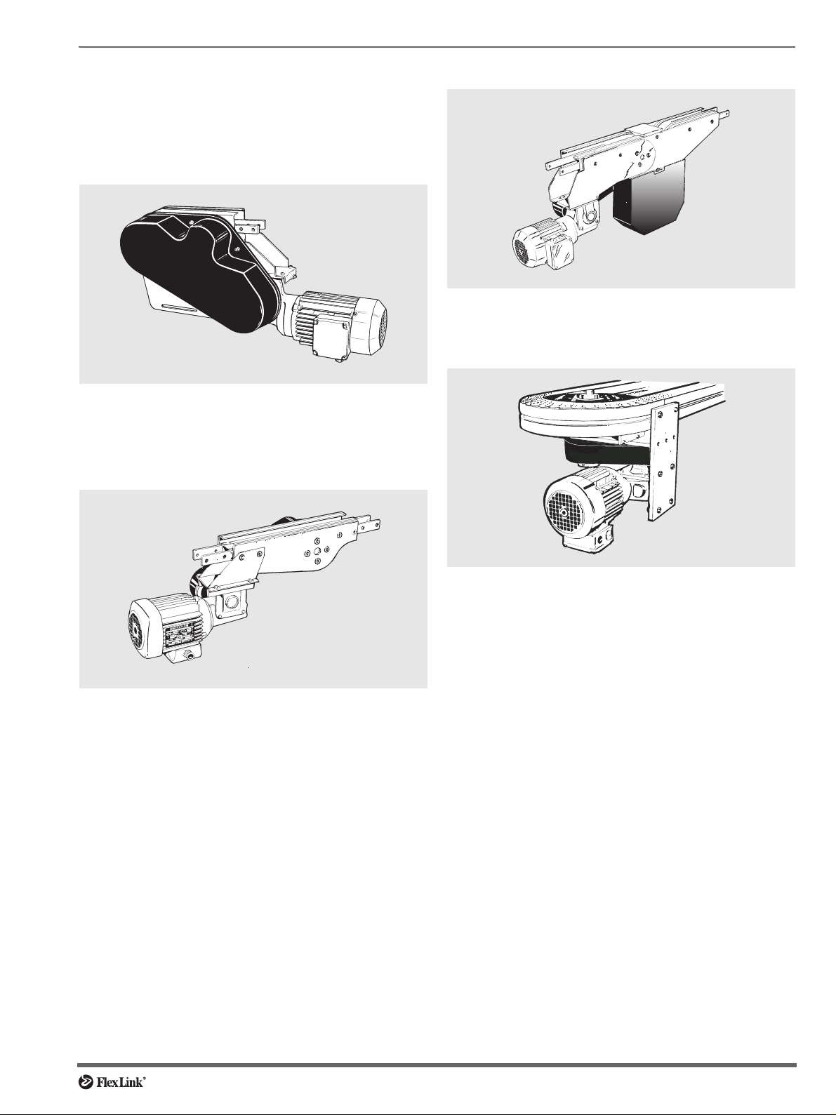
There are four different types of drive unit: end drive
units, intermediate drive units, catenary drive units and
horizontal bend drive units.
End drive units
End drive unit with return chain, located at the ‘pulling’
end of the conveyor. End drive units are either transmission chain types (see picture) or direct drive types.
Intermediate drive units
Catenary drive units
Catenary drive unit without return chain, located at an
intermediate position along the conveyor.
Horizontal bend drive units
Intermediate drive unit located at an intermediate position along the conveyor.
Horizontal bend drive unit for driving endless conveyors
without return chain.
Chain transmission
The drive units are normally fitted with roller chain transmission. Some end drive units come with direct drive.
Note
The roller chain transmission has chain guards and gearing protection. These guards should always be in position
when the conveyor is in operation.
Maintenance
5
Page 6
Slip clutch adjustment
Old and new versions
The slip clutch is available in two versions. Shipping of
the new version began in 2001. Adjustment of both versions are described here.
Introduction
The slip clutch on the drive unit is a safety device which
allows the chain to stop if the load becomes excessiv e. It
has two purposes:
• Prevent damage to conveyor
• Prevent damage to the products on the conveyor
Where a slip clutch is fitted, it must be adjusted so that it
does not slip whenever the drive unit is started under full
load. The installation is carried out as follows:
Preparations for adjustment
1 Stop the conveyor.
2 Ensure that the conveyor can not be started acciden-
tally. For example: unplug the electric power plug.
3 Remove any load on the conveyor.
Caution:
If you try to adjust the slip clutch when
there is still load on the conveyor, the
accumulated tension in the chain can
cause severe injuries when you release
the clutch.
Slip clutch should not be adjusted until
1 Motor direction is confirmed
2 Conveyor is fully assembled
Important:
The slip clutch is not a personal safety
device. It is primarily intended to protect the
equipment.
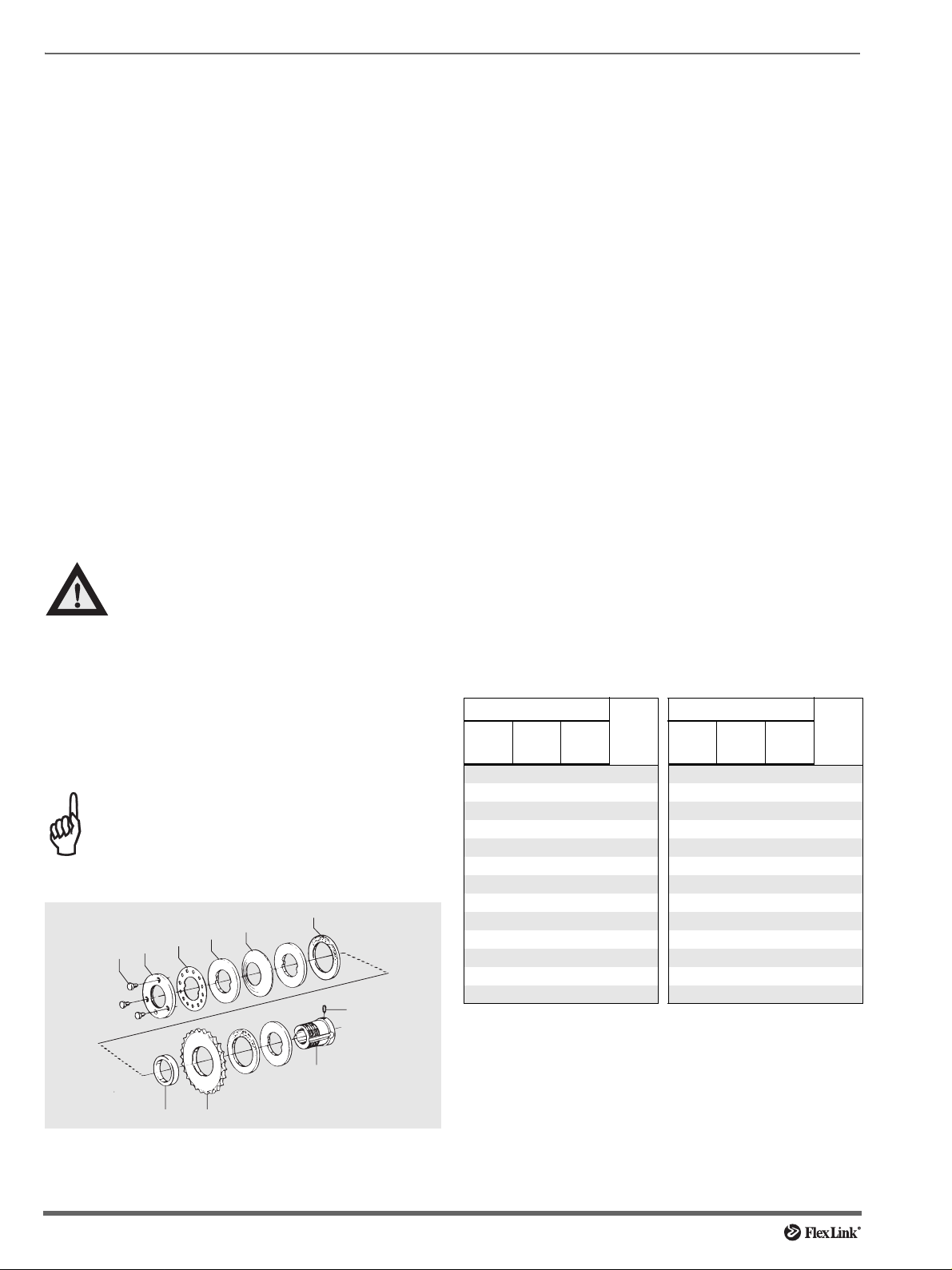
Clutch adjustment, old type
9
5
6
7
8
4
10
2 Unscrew the three screws (8) so that the outer ring (7)
can be rotated freely.
3 Hand-tighten the outer ring (7) to stop (no tools!).
4 Look for the desired maximum traction force in the
table to the right and determine the X value for that
force.
5 Positive X-value: (If the X value is negative (X≤0)
ignore step 5 and go to step 6.) Turn the outer ring (7)
counter-clockwise the number of divisions given by
the table, i.e. the X value. One division is defined as
the angle (30°) between adjacent holes in the stop
ring (6). Check that screws (8) align with the holes in
the stop ring (6).
6 Negative X-value: (If the X value is positive (X≥0)
ignore step 6 and go to step 7.) Turn the outer ring (7)
clockwise with a hook wrench, the number of divisions
given by the table, i.e. the X value. One division is
defined as the angle (30°) between adjacent holes in
the stop ring (6). Check that screws (8) align with the
holes in the stop ring (6).
7 Tighten the three screws (8) to stop. Use 10 mm
wrench
Clutch adjustment table, old type
F
is the desired maximum traction force applied to the
max
chain by the drive unit. The clutch will start slipping at
forces above F
max.
Note
The values in the table are approximate and apply to
factory-new slip clutches.
Traction force F
XSXLXM
XH
XW
450 450 100 19 1200 1200 1400 6
475 475 200 18 1300 1500 5
1000 1200 8 2500 –5
1100 1300 7
(N) X (div.) Traction force F
max
XK XMXHXW XK
525 300 17 1400 1600 4
575 400 16 1525 1700 3
625 500 15 1800 2
675 600 14 1900 1
725 700 13 2000 0
775 800 12 2100 –1
825 900 11 2200 –2
875 1000 10 2300 –3
925 1100 9 2400 –4
(N) X (div.)
max
3
2
1 Remove the transmission cover.
6
1
Maintenance
Page 7

Slip clutch adjustment (continued)
Clutch adjustment, new type
3
1 Remove the drive unit protection cover.
2 Use an Allen key , 3 mm, to loosen the scre w (1) on the
slip clutch so that the adjustment nut (2) can be freely
rotated.
3 Turn the adjustment nut (2) clockwise with a hook
spanner until the arrow on the nut is aligned with the
desired F
value (3). See the follo wing table f or cor-
max
rect values.
Note: On delivery, the clutch is always set to “0”.
4 Tighten the screw (1).
5 Re-install the drive unit protection cover.
2
1
Traction force, F
No.
0 300 300 300 600
1 400 400 400 800
2 500 500 500 1000
3 700 700 1150
4 800 800 1300
51550
6 1050 1050 1700
7
8 1250 1250 2000
9
10 1400 2200
11
12 1500 2400
13
14 1650 2500
XS
XL
Standard and direct drives 1/2”:
Slip clutches marked 3904324,
5052769, 3925774, 5052827
XM, XH
XK, XB
(N)
max
XT XK H
Standard drives 5/8”:
Slip clutches marked
3925071, 5052772
Clutch adjustment table, new type
is the desired maximum traction force applied to the
F
max
chain by the drive unit. The clutch will start slipping at
forces above F
max.
Hook spanner
Maintenance
7
Page 8

Inspection – drive units
Roller chain transmission
The roller chain transmission should be checked and
lubricated after 50, 250, 500 hours of operation, and then
every 500 hours.
If the roller chain transmission is not fitted with a chain
tensioner the chain tension should be checked on this
occasion.
At the same time as the roller chain tension is
checked, the chain must also be lubricated with a suitable chain spray or similar.
If the transmission is fitted with a chain tensioner,
lubrication should only be carried out at the stated intervals. The condition of the chain tensioner must be
checked at the same time as the lubricating is done.
Note
The discs in the slip clutch must be kept free from oil and
grease.
Worm gear motor and geared motor
The worm gear or geared motor is checked in accordance with the instructions from the relevant supplier.
Guide for the conveyor chain
The purpose of the guide for the conveyor chain is to
guide the return chain correctly into the drive unit.
Fully enclosed drive units do not have guides. On
these, no slack is permitted at the drive unit since the
conveyor chain is being controlled all the time. Special
attention must be given to chain elongation in conv e y ors
of this configuration.
If guides are fitted they can be of two different types:
• Loose disposable guides in plastic.
Replaceable chain guides
• Guides integrated into the ends of the drive unit...
Chain guides integrated into ends.
General checks on drive unit
Carry out a general inspection of the drive unit.
• Check particularly that the protective covers for the
roller chains are complete and firmly in place.
• Replace damaged/worn parts.
8
Maintenance
Page 9

Inspection – conveyor chains
Conveyor chains
The most common types of conveyor chains are:
• Plain conveyor chains.
.
Plain conveyor chain
• Chain with cleats for inclined or vertical conve yor sections. The cleats are generally spread over the chain
at a predetermined distance.
Cleated, friction and wedge chains
Cleated chains, friction chains and wedge chains, or
other special chains should be inspected regularly, and
any defective links replaced or cleaned.
Warning
Only warm water (50°C), with soap if necessary , ma y be
used for cleaning conveyor chains.
• Check the guards on cleated chain conveyors.
Checking the tension of conveyor chain
The chain is made of elastic material. The chain eventually stretches as the material creeps. The extent of the
stretch depends on the traction force in the chain. The
stretch shows itself as slack on the return side of the
drive unit.
The tension of the conve yor chain should be check ed
after 50, 250, 500 hours of operation and thereafter every
500 hours.
In operation there will be some slack in the conveyor
chain. How much slack is acceptable depends on the
length of the convey or chain. The most suitable places to
check the slack in the chain are at intermediate or end
drive units.
Cleated chain
• Chain with flexible cleats for vertical wedge conveyors.
Chain with flexible cleats
• Chain with friction surface for conveyors with an
incline up to 30°. The friction surfaces are normally
distributed over the chain at a predetermined distance.
Chain with friction surface
Maintenance
9
Page 10

Inspection – conveyor chains (continued)
Important:
The chain should therefore be pre-tensioned while the
conveyor is stationary, but must never be so tight that
there is no slack during operation. There should be no
appreciable slack on the chain when the conveyor is stationary. This can, however, vary depending on the total
length of the chain. If there is too much slack, there will be
excessive wear on the chain guides and the chain. This
could be a risk for injury.
If the slack on the conveyor chain is unacceptably
high, it must be shortened by splitting the chain and
removing the necessary number of links. See “Shortening conveyor chains” on page 10.
If the conveyor has a guided drive unit with no chain
slack take up , the elongation of the chain has to be monitored even more carefully, to ensure a trouble free operation.
Beam section for chain installation
• by removing the side plates of the drive or idler end
unit in closed systems.
• at a wheel bend by removing the outer curve.
• at a convey or beam section for liftable chain (if there is
any).
Instructions
1 Make the conveyor chain accessible at some of the
overhead positions.
2 Remove the steel pin (1) from the pivot (2). Use the
pin insertion tool (see figure).
3 Remove the necessary number of links.
The conveyor chain must show some slack during
operation.
The conveyor chain does not need to show any slack
when the conveyor chain is stationary.
Shortening conveyor chains
The most suitable place to shorten the chain is at the
drive unit.
Alternatively:
• at a beam section for chain installation which has
detachable sections.
Chain joint components
Note. With cleated or friction chains, pay attention to
the divisions between the links.
4 Join the chain together with a new pivot.
Note. The old pivot should not be re-used. When the
chain is divided, a new pivot must always be fitted.
5 Insert the steel pin using the pin insertion tool.
6 After inserting the steel pin, check that it is centered
and that the chain easily bends in the fitted link.
10
Usage of pin insertion tool
Maintenance
Page 11

Inspection – slide rails, beams, idlers, bends
25
100
Checking slide rails
The condition of the slide rails is fundamental to the functioning of the installation. It is therefore essential that
these are in good condition.
Checking the slide rail with the conveyor chain in place
The slide rail must be checked after every 250 hours’
operation. Carry on the checking on a stationary conveyor with the chain in place.
• Check the fastening points on the slide rail.
• Check the joints on the slide rail.
4
5
25
10
50
Correct configuration of joints
• Check that there is a gap between the slide rails and
that the joints are correctly fitted.
• Check that the joints are not deformed.
Checking the slide rail, conveyor chain removed
At least once a year or after ev ery 2 000 hours’ operation,
the chain should be removed from the beam, and the
slide rail carefully checked for wear and fastening.
Plain bends should be checked after e very 500 hours’
operation, since these are subjected to higher loads.
• Carry out the same checks as were carried out during
“Checking slide rails with the conv eyor chain in place”.
• Check the slide rail for wear and tear.
Note
Check in particular the inner slide rail in plain bends,
since the stresses here are particularly high.
• Check the slide rails for scratches and notches.
• Replace the slide rail and fasteners if necessary, see
“Replacing slide rails” on page 14.
Wash the conveyor chain.
Conveyor beams, idler ends, and bends
The convey or beams themselves do not normally require
any regular inspection. Be observant for damage arising
from external factors, warping or deformation. Deformation can cause the conveyor chain to jam, resulting in
uneven running.
Idler ends and wheel bends do not normally require
any special inspections, but they should be checked
when the slide rails are inspected.
Large radius plain bends may hav e inner support rails
fitted to the beam. Ensure that these rails (if fitted) are not
worn, paying particular attention to the “lead-in” area.
Deformed joints
• Check that the slide rail has not been broken off.
Replace the slide rail if necessary, see “Replacing the
slide rail”, beginning on page 14.
Maintenance
Inner support rails
11
Page 12

Inspection – safety devices
Protective and safety devices
Safety devices should be checked at regular intervals.
• Check the chain guard for roller chain transmission.
This guard must always be in place when the conveyor is in motion.
• Check the protective cover on the cleated chain conveyor return chain.
• Drive units type H, have a slac k protection for the conveyor chain. Chec k that the slack protection plates are
in place, and that the chain does not slacken enough
to hang below the plates.
• Check the protective cover for the conveyor chain on
intermediate drive units and catenary drive units.
• There may be other types of guard which are specific
to your installation, and these must also be checked.
See the system documentation.
Chain guard for roller chain transmission
Slack protection plate for drive unit type H
12
Maintenance
Page 13

Replacement of worn parts – conveyor chain
Removal of conveyor chain
1 Ensure that the power to the drive motor is discon-
nected.
2 Disengage the motor; there are various methods
depending on the type of drive unit:
— Detach the slip clutch.
— Remove the roller chain.
— Disengage the gear from the drive wheel.
3 Split the chain by removing the steel pin from the
pivot. Use the special tool for insertion/removal.
4 Pull out the chain.
Sample for checking conveyor chain space
2 Put the new conveyor chain in place. Check that the
chain direction corresponds to the convey or direction.
Pin insertion/removal tool
Fitting the conveyor chain
1 Run a sample (approx. 0.3 m) of conveyor chain
through the installation in the direction of the conveyor. Check that the chain moves easily and correctly through the bends and idler ends. Check at the
same time that there is enough space for the chain.
The conveyor chain direction
Note
Be careful that the first link of the conveyor chain does
not damage the slide rails.
Immediately investigate the reasons f or any jamming and
take immediate action.
3 Shorten the conveyor chain to the right length. Fit the
pivot and the steel pin, using the special pin insertion/removal tool.
After fitting, check that the steel pin is centered and
that the chain can easily bend in the fitted link.
4 Check that the slack is not e xcessiv e . See “Chec king
the tension of conveyor chain” on page 9.
Maintenance
13
Page 14

Replacement of worn parts – slide rails
XLMR 140
40
0
0
Replacing slide rails
It is very important to assemble slide rails correctly to
ensure smooth system operation.
Follow the illustrated instructions on the following
pages carefully. Observe the following points:
• Single-cut pliers are suitable tools for cutting the slide
rails.
Single cut pliers
• Use mounting tool for slide rail XLMR 140,
XMMR 140, XHMR 200, or XKMR 200.
XMMR 1
XHMR 20
XKMR 20
1
2
Mounting tool for slide rail
• Use drill fixture 3920500. The distance between
anchor points must be 50 mm.
• Use a high quality drill bit to avoid forming a shoulder ,
preferably one which is intended for drilling aluminium.
• Use XLAH 4×6/XLAH 3×6 rivets.
When fitting the slide rails with rivets, the fitting instructions on page 15 must be followed.
• The joints on the slide rails must have a distance of
100 mm between them. The joints should be laid out
as in the picture with a gap of approx. 10 mm between
the rails.
• Joints may not be positioned in bends, or in the transition between two sections of beams.
• The slide rails should normally be approximately 5 m
long on a straight conve yor beam. In a bend, the maximum length of slide rail should be 3 m.
• The joints should be positioned a minimum of 500 mm
before an idler end unit, drive unit or vertical bend.
The slide rail must overlap the recess in the idler end
and drive unit.
• The inner slide rail after a wheel bend must be cut so
that the cut surface is parallel to the wheel. In front of
the wheel bend, the slide rail will normally be cut at
45°.
Note
Check the final slide rails visually, as well as running a
section of conveyor chain through the installation.
An alternative to the aluminium rivets, is to use the plastic
screws XLAG 5 (XW A G 5 for XK). See page 16 f or fitting
instructions. The holes for the plastic screws are
threaded with a tap.
∅
Drill fixture 3920500
14
Maintenance
Page 15

Anchoring slide rail
Fixing slide rail to the conveyor beam
Hand drill
Drill fixture for slide rail 4,2 mm (XS: 3,2 mm)
Countersink
The beginning of each slide rail section must be fixed to
the beam, since the chain will cause the slide rail to be
pushed forward. Slide rail which mo ves into a wheel bend
or a drive unit can block the chain completely.
There are two different methods f or fixing slide rail to
the conveyor beam: using aluminium rivets or plastic
screws. Either method can be used, but the riveting
method is more secure if the conveyor will run with high
operational speed or be heavily loaded.
wrong
correct
Method 1: Using aluminium rivets
Rivet crimping pliers/rivet crimping clamp
Aluminium rivets
Mounting:
1 Insert rivets in the holes, using rivet crimping pliers or
a rivet crimping clamp. For type of rivet, see table on
previous page.
3 Check that the rivets do not protrude over the surf ace
of the slide rail.
Check both top and underneath surface of slide rail for
protruding metal.
4 Keep a distance of appro ximately 30 mm between riv-
ets and idler unit. This is in case the idler unit has to
be removed after conveyor system assembly.
2 If working space is limited, the rivet crimping clamp
might be easier to use. The two crimping tools per-
form the same task, but the pliers are more efficient
and easier to use.
Maintenance
15
Page 16

Anchoring slide rail (continued)
Method 2: Using plastic screws
Pliers/screwdriver
Knife
Hammer
Plastic screws XLAG 5
An alternative to aluminium rivets is to use plastic screws
XLAG 5:
Mounting:
3 Make sure the slide rail surface is smooth and that
screws do not protrude over the surface of the slide
rail. If the surface should be uneven, file the edges
smooth.
Check both top and underneath surface of slide rail for
protruding plastic or metal.
1 Press or screw the screws into the holes using a pair
of pliers or a screwdriver.
2 Cut off the screw heads by using a knife and a ham-
mer. The cut should be made away from the joint, in
the direction of chain travel.
4 Keep a distance of approximately 30 mm between
screws and idler unit. This is in case the idler unit has
to be removed after conveyor system assembly.
16
Maintenance
Page 17

Troubleshooting
Jerky running
Cause Corrective action
Damaged or badly fitted
slide rail
Wrongly adjusted slip
clutch
Worn transmission parts Check/replace transmission chain, chain
Conveyor chain is too
tight/loose
Dirty conveyor Clean conveyor chain/slide rail. Lubri-
Inspect and replace as necessary.
Check and adjust slip clutch.
drive sprocket.
Tension conveyor chain correctly.
cate with silicone based lubricant.
Drive unit is running, conveyor chain is not
Cause Corrective action
Wrongly adjusted slip
clutch
Friction discs in slip clutch
are worn or contaminated
Damaged/badly fitted slide
rail
T ransmission products are
not fitted
Check adjustment of slip clutch.
Check and replace if necessary.
Check the free running of the conveyor
chain.
Check and fit.
Motor overheating on drive unit
Cause Corrective action
Overloaded conveyor Remove products from conv eyor and test
Gearbox leaking oil Check output shaft seal and area around
Dirty conveyor Clean the conveyor chain with warm
run.
Check actual conveyor load against rec-
ommended loading.
motor/gearbox interface.
water (50°).
Noise
Cause Corrective action
Worn or damaged bear-
ings in drive unit
Damaged/badly fitted slide
rail
Excessive conve yor speed Lower speed.
Incorrect conveyor chain
tension
Check/replace drive unit.
Check the free running of the conveyor
chain, especially in slide rail joints.
Check actual load against recommended
loading.
Lengthen/shorten conveyor chain.
Abnormal wear on plastic parts
Cause Corrective action
Overloaded conveyor Remove products from conveyor
Ambient temperature too high Check against recommended
Chemicals in the environment are
affecting plastic parts
Damage due to ingress of contaminate
Particles, swarf etc. Remove source of contamination.
and test run.
Check the free running of the con-
veyor chain.
Check actual conveyor load
against recommended loading.
temperature for conveyor.
Check in FlexLink main catalogue
(section TR) for listing of incompatible chemicals.
Clean the system.
Troubleshooting
17
Page 18

Checklist/maintenance schedule
No. General checks Number of operating hours/time interval See page
1. Check roller chain, sprocket, chain tension and lubrication of drive unit
2. Check/adjustment of slip clutch Every 1 000 hours Page 6
3. Check conveyor chain guides in drive units and idler
ends
4. Check tension of conveyor chain 5 0 250 500 Then every 500 hours Page 9
5. Check slide rails Every 250 hours Page 11
6. Check slide rails, conveyor chain removed. Every 2 000 hours, or at least once a year Page 11
7. Check slide rails in plain bends. Every 500 hours Page 11
8. Check safety and security devices At least once a year Page 12
50 250 500 Then every 500 hours Page 8
Every 1 000 hours Page 8
18
Checklist/maintenance schedule
Page 19

System dismantling and disposal
Important safety precautions
Dismantling
Dismantling of the FlexLink conveyor system should be
carried out by competent persons, who are familiar with
the equipment being decommissioned.
In the absence of detailed information, every care
should be taken to ensure that all items are securely
retained during the decommissioning process. This is to
ensure that the equipment remains stable and will not fall
if left unattended.
If pneumatics or hydraulics are to be decommissioned, special attention should be given for the safe
release of any accumulated pressure from within the circuitry. All reservoirs/accumulators must be depressurised prior to removal.
If there are any doubts as to the most suitable procedure for decommissioning, then consult the equipment
supplier.
Conveyor system XS, XL, XM, XH, XK, and XB
To dismantle a FlexLink conv eyor the following tools are
required.
Ring spanners /10 mm and 13 mm size
Allen keys
Pin insertion tool XS/XL = XLMJ 4
Pin insertion tool XM = XMMJ 6
Pin insertion tool XH = XHMJ 6
Pin punch XK = XKMJ 8
Hammer
Drill to remove slide rail rivets
1 Remove any remaining product from the conveyor
system.
2 Switch off all electrical power and disconnect all pneu-
matic and hydraulic feeds, including accumulators.
Ensure that system is safe by shutting down all feed
supplies or removing electrical fuses.
3 Remove the black transmission cover from drive unit
to expose slip clutch and transmission drive chain.
4 The locking effect of the slip clutch can be remov ed by
removing the transmission chain or by releasing the
slip clutch (section in maintenance and service refers
to slip clutch adjustment).
5 Remove the motor gear unit from the conveyor drive
assembly . The motor gear unit may be fitted with an oil
breather. Ensure that the oil from the gearbo x cannot
leak into the surrounding area when decommis-
sioned. Oil should be drained from the gearbox and
disposed of in accordance with local environmental
regulations.
6 Remove guide rails and guide rail brackets etc.
7 Split the conveyor chain using the pin insertion tool
and remove the conv eyor chain. If remo ving conv eyor
chain from over head conveyor special attention
should be given when removing the last few metres.
The weight of the removed chain accelerates the
removal from the conveyor beams and can cause
injury when the last links exit the extrusion. The chain
should always be removed in the conveyor working
direction.
8 Unscrew the inner grub screws from the drive unit
connector strips and remove drive end from the conveyor. Repeat for idler end unit.
9 Remove the slide rail on all sides of the conveyor
extrusion. Remove the slide rail retaining fixings by
drilling away the rivets or plastic screws and pulling
away the slide rail from the aluminium extrusion profile.
10 Dismantle the conveyor extrusions from the support
brackets . This should be done in a systematic manner, removing conveyor section by section. Where
extrusions are joined by connecting strips, first
untighten the retaining grub screws from the connection strips. It may be necessary to release the clamp
effect of the connector piece by giving a sharp tap
with a hammer.
11 Dismantle the conveyor support system into separate
components.
12 Sort different materials ready for disposal. Include a
list of the materials.
If other equipment is to be dismantled simultaneously
with the FlexLink conveyor, attention should also be
given to the interaction of the other equipment to the
FlexLink conveyor. Pneumatic equipment should be
removed from the conv eyor before dismantling. Hydr aulic
equipment should also first be removed to assist dismantling and handling of the conveyor components during
dismantling and disposal.
System dismantling and disposal
19
 Loading...