

Page 1

r
5683EN
Conveyor system WL
Conveyor assembly manual
eated by EBCCW 00:06
Created by EBCCW 96:05Created by EBCCW 00:06Created by EBCCW 96:05Created by EBCCW 00:06
C
Page 2

Created by EBCCW 96:05Created by EBCCW 00:06
Page 3

r
5683EN
Conveyor system WL
eated by EBCCW 00:06
Created by EBCCW 96:05Created by EBCCW 00:06Created by EBCCW 96:05Created by EBCCW 00:06
C
Page 4

Created by EBCCW 96:05Created by EBCCW 00:06
Page 5

1 About this manual 3
1.1 Introduction 3
1.2 Document disposition 3
1.3 Installation site preparations 3
1.4 Assembly order 4
2Tools 5
2.1 General tools 5
3 FlexLink tools 7
4Fasteners 9
4.1 Standard screws, nuts, washers 9
4.2 Slot nuts and square nuts 9
4.3 Connecting strips 10
4.4 T-bolts 11
5 Assembly 13
5.1 Introduction 13
6 Support design 15
6.1 Special tool when mounting feet 15
7 Beam assembly 17
7.1 Support profiles 17
8 Drive and idler unit assembly 19
9 Slide rail and support rail 21
10 Belts 23
10.1 Roller Kit 26
11 Final preparations 29
5683EN-1
Created by EBCCW 00:06
1
Page 6

11.1 Plug beam ends 29
11.2 Anchor feet to the floor 29
11.3 Other preparations 29
12 Start-up and testing 31
12.1 Safety considerations 31
12.2 Slip clutch adjustment 32
12.3 Start-up 34
13 Troubleshooting 37
13.1 Jerky running 37
13.2 Drive unit is running, conveyor belt is not 37
13.3 Motor overheating on drive unit 37
13.4 Noise 38
13.5 Abnormal wear on plastic parts 38
14 Appendix 39
2
5683EN-1
Page 7

About this manual
1 About this manual
1.1 Introduction
The main purpose of this manual is to help self-building end users, with little
or no prior experience, to assemble a FlexLink WL conveyor system.
Each chapter includes instructions and pictures showing how to assemble
the different parts.
1.2 Document disposition
The document is divided into the following five main parts:
• Installation site preparations
• Tools and fasteners
• Cutting FlexLink beams
• Assembly
• Start-up and testing
1.3 Installation site preparations
1.3.1 Assembly planning
Work systematically:
1 Prepare by studying your assembly drawing.
2 Ensure that the necessary tools are available.
3 Make sure you have all the materials and components needed to
assemble the conveyor system. Check with the parts list.
4 Make sure you have enough floor space to mount the conveyor
system.
5 Check to see if the floor at the installation site is even, so that all
feet can be properly attached to the floor.
5683EN-1
Created by EBCCW 00:06
3
Page 8

About this manual
1.4 Assembly order
The following list can be used as a checklist during your conveyor assembly work:
Activity
Cut all beams into suitable lengths
Connect feet and structural beams
Mount conveyor beam support brackets
Assemble conveyor beams and mount
them on to the support structure
Mount drive and idler units to the ends of
the conveyor
Mount slide rail on to the conveyor beam
Loosen the drive unit slip clutch
Run a short piece of chain through the
conveyor to check that there are no
obstructions
Assemble and mount the chain on to the
conveyor
Mount guide rail, drip trays and other
accessories on to the conveyor
Tighten the slip clutch to a suitable friction
Read Final preparations at the end of
this manual
Check
4
5683EN-1
Page 9
2Tools
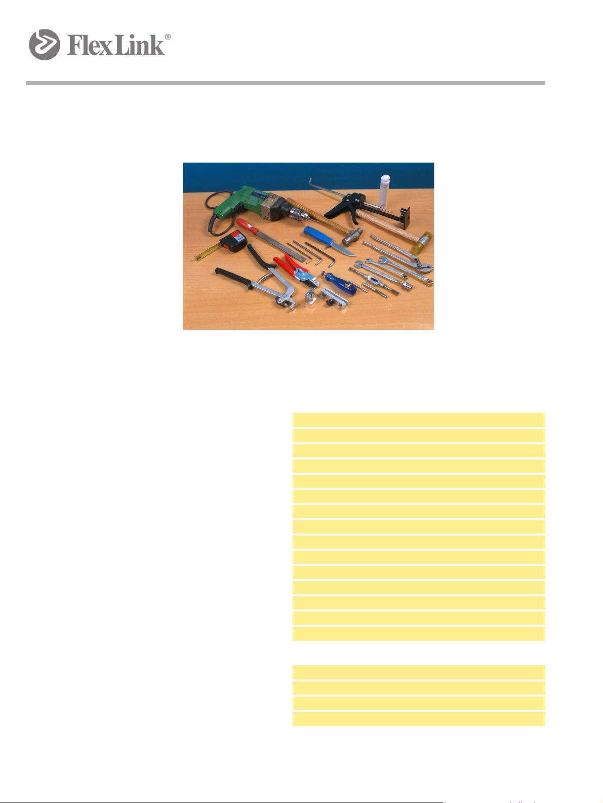
2.1 General tools
Tools
To assemble a FlexLink conveyor, you will need most of the tools listed on
the following pages. Not all are essential, but they will make your assembly
work easier and more efficicient.
Hand tools
10 and 13 mm box wrench
Cutters (for cutting slide rail)
Set of metric Allen keys
Roller thread fluteless tap and tap wrench (M6 and M8)
Countersink bit
Tape measure
In addition, the tools listed below can be useful:
Files
Socket wrench
Screw-driver
Pliers
Knife (for cutting off plastic screw heads)
Soft faced hammer
Clamp (for chain installation)
Level
Power tools
Cross-cut circular saw for aluminium
Hand drill
Drill bit (for fixing of slide rail):
XS: ∅3,2 mm, XL/XM/XH/XK: ∅4,2 mm
5683EN-1
Created by EBCCW 00:06
5
Page 10

Tools
6
5683EN-1
Page 11
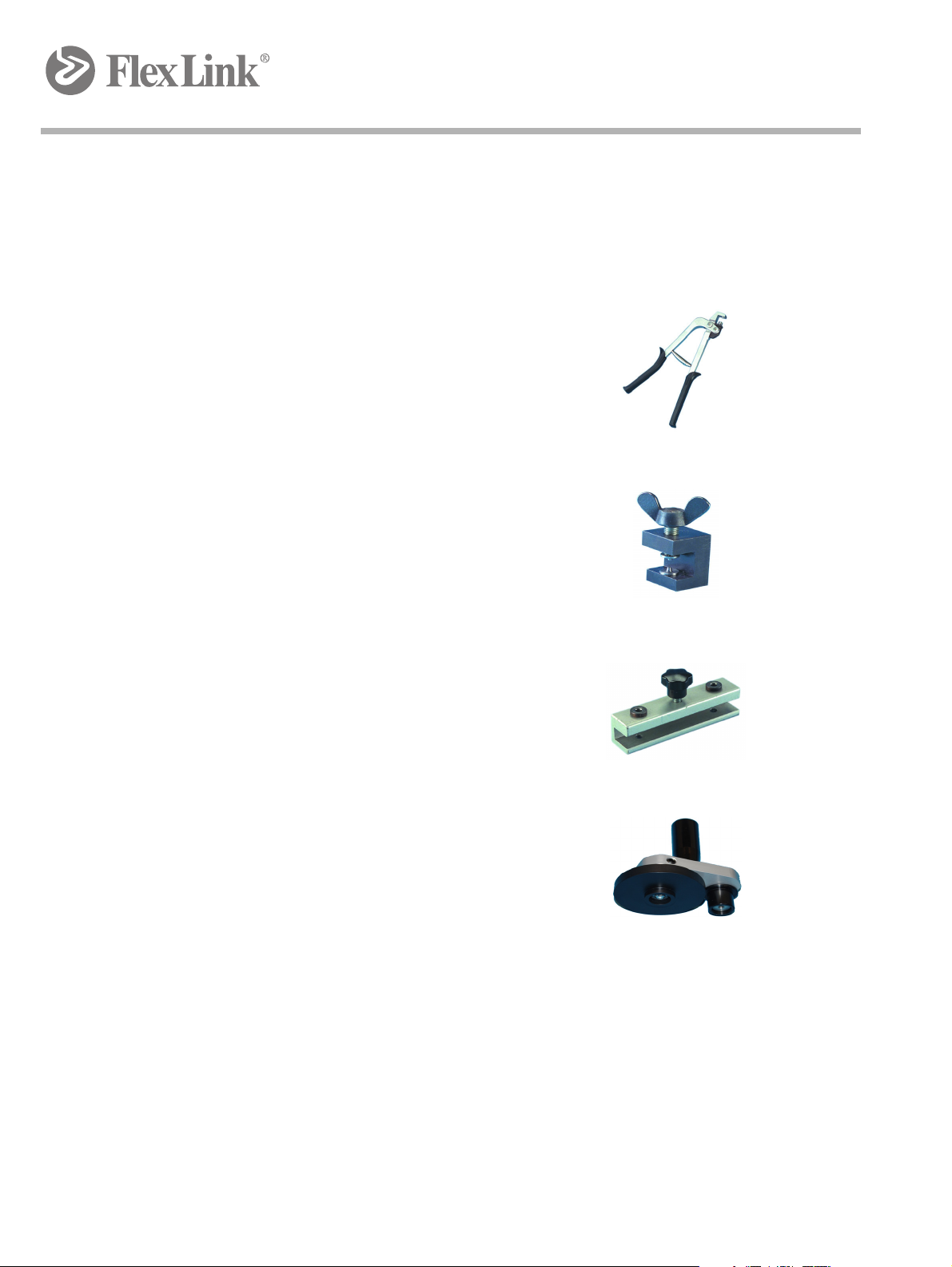
3 FlexLink tools
Rivet crimping pliers
XS (∅ 3 mm):
3924776
XL/XM/XH (∅ 4 mm):
3925800
Rivet crimping clamp
XS (∅ 3 mm):
3924770
XL/XM/XH (∅ 4 mm):
3923005
The riveting tools have replaceable pads. By
replacing the pads you can use the same riveting
tool for 3 mm and 4 mm rivets.
FlexLink tools
Drill fixture for installation of slide r
XS (∅ 3,2 mm):
3924774
XL/XM/XH/XK (∅ 4,2 mm):
3920500
Mounting tool for slide rail
WLMR 135
a
il
5683EN-1
Created by EBCCW 00:06
7
Page 12

FlexLink tools
Rivet crimping pliers
XS (∅ 3 mm):
3924776
XL/XM/XH (∅ 4 mm):
3925800
Guide rail bending machine
3922963
(not shown)
Drill fixture for fastener yokes
8050040
The drill fixture is slided into the stand and fixed by
tightening the star knob.
8
5683EN-1
Page 13
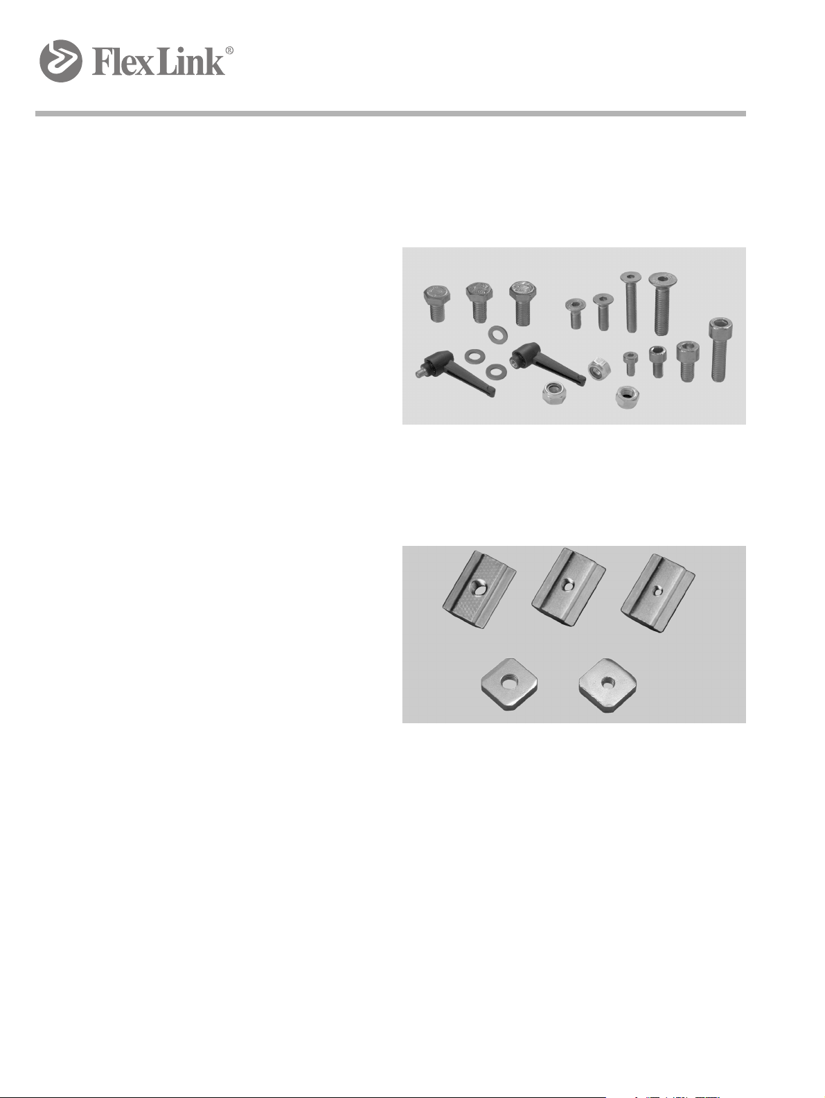
4 Fasteners
4.1 Standard screws, nuts, washers
M6S, MC6S, MF6S, M6M, BRB 8,4×16, XLAL
Fasteners
4.2 Slot nuts and square nuts
XCAN, XLAQ
Square nuts can be used in support beams and small beams instead of
XCAN nut
XCAN nuts. They do not stay in place in vertical positions and have to be
inserted from the beam end.
When using XLAQ square nuts, remember to put in a sufficient number before completing the assembly.
s, but they can also be used in conveyor beams as opposed to
5683EN-1
Created by EBCCW 00:06
9
Page 14
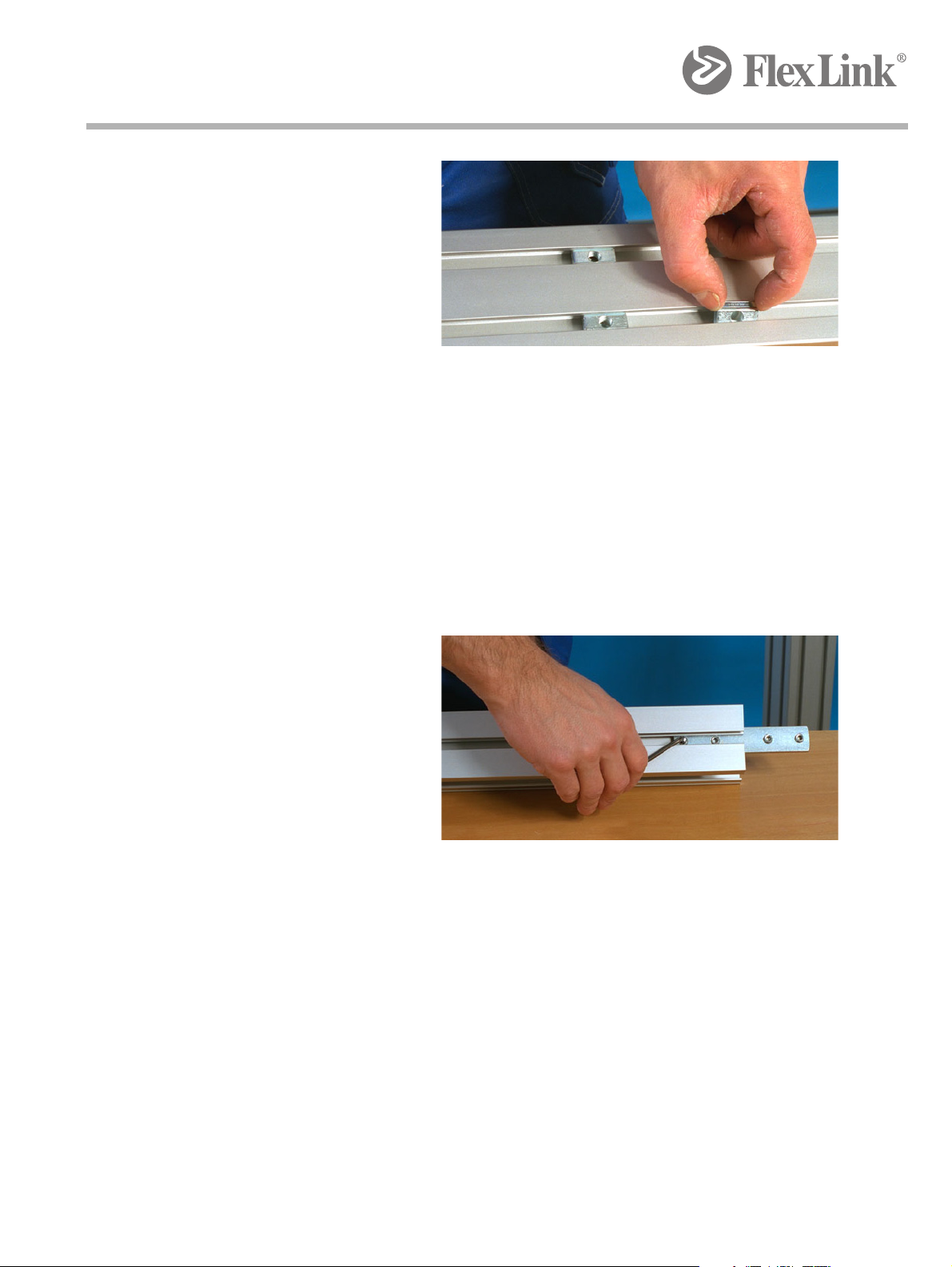
Fasteners
IMPORTANT
Figure 1 XCAN
On the support beam, the slot nut can be entered into the T-slot from the
beam side. It will s
tay in position in vertical T-slots because of a thin leaf
spring.
Slot nuts can not be used with conveyor beams.
4.3 Connecting strips
Figure 2 Connecting strips
Connecting strips are used for joining beams together, end to end. Use Allen key and set screws when attaching the connecting strip to the beam.
10
5683EN-1
Page 15
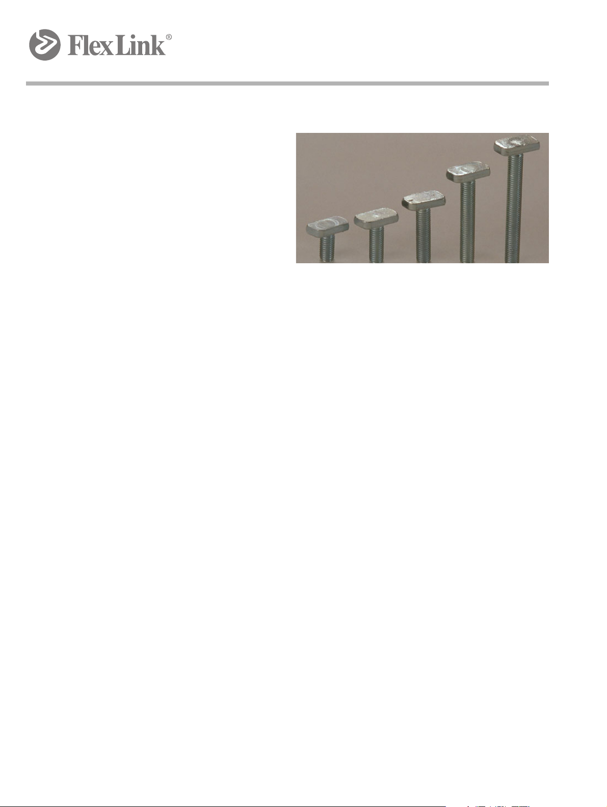
4.4 T-bolts
Figure 3 XLAT
Fasteners
T-bolts can be entered from the beam side, and when turned 90° they
will
stay in place after tightening with nuts (XLAN 8) and washers (BRB
8,4×16). The indication groove in the T-bolt should be at 90° to the conveyor T-slot.
T-bolts are used when attaching support brackets, guide rails and drip trays
the conveyor beam. Do not use T-bolts with support beams!
to
5683EN-1
Created by EBCCW 00:06
11
Page 16

Fasteners
12
5683EN-1
Page 17

5 Assembly
5.1 Introduction
Assembly
5.1.1 Component groups
The basic FlexLink conveyor structure
• support structure
• conveyor beams, straight sections and bends
• drive and idler units
•chain
• other accessories (guide rail, drip trays etc.)
The first step in the assembly process is to
which consists of feet, support beams and beam connectors. Most conveyor support designs are based on vertical su
essary, with horizontal support beams. The
5683EN-1
Created by EBCCW 00:06
consists of five component groups:
assemble the support structure,
pport beams combined, if nec-
re are also a number of different
13
Page 18

Assembly
feet and beam connectors, so check which ones are used in your application. Some examples are shown below.
IMPORTANT
You must work in accordance with your layout, and make sure that the conveyor is supported at regular intervals not exceeding 3 m.
14
5683EN-1
Page 19

Support design
6 Support design
The WL conveyor system uses standard FlexLink feet, refer to appendix for
assembly instructions.
5683EN-1
6.1 Special tool when mounting feet
Conveyor beams are mounted on to the support structure by means of support brackets. To get the right distance betw
template. The drilling template are fitted on the support structure using the
T-slots. Tighten the star knob before drilling.
een the holes, use the drilling
15
Created by EBCCW 00:06
Page 20

Support design
16
5683EN-1
Page 21

Beam assembly
7 Beam assembly
The beams is connected using the Connecting strips for beam.
7.1 Support profiles
Note the different location of the support profiles due to belt width. See table below for placement of the support profiles.
5683EN-1
Created by EBCCW 00:06
17
Page 22

Beam assembly
18
5683EN-1
Page 23

Drive and idler unit assembly
8 Drive and idler unit assembly
This step is to mount drive and idler units to the frame structure. All drive
and idler units come with connecting strips included. Attach them to the
conveyor beam using an Allen key and the set screws that are included.
Drive units can be attached to supports of various kinds; check your drawing to see how your conveyor is designed.
It should be remembered that conveyor
pushed, by the drive unit.
1.
2.
belt should always be pulled, not
5683EN-1
Created by EBCCW 00:06
19
Page 24

Drive and idler unit assembly
20
5683EN-1
Page 25

Slide rail and support rail
c
b
a
c
9 Slide rail and support rail
Slide rail and support rail is standard FlexLink equipment and are therefore
described in another guideline.
The slide rails used in the WL conveyo
as shown below.
a WLCS 25x5 H - Mount this first (not neccessary for supportlist)
b XBCR 25 HB - Mount as number two
c XBCR 25 H - Mount as number three
r system are mounted alphabetically
Use the mounting tool for slide rail. Mount the slide rails in the order described above.
5683EN-1
Created by EBCCW 00:06
21
Page 26

Slide rail and support rail
22
5683EN-1
Page 27

Belts
10 Belts
The belts is delivered in one meter section to be manageable. They are
mounted in the conveyor using the belt insertion section. The belt should
be mounted with the front in the running direction.
1. Unscrew the two screws and remove the
2. Inserting the belt from the top: insert the front of the belt pointing
ds the engine.
towar
Inserting the belt from the bottom: inse
from the engine.
cover on both sides.
rt the front of the belt pointing
5683EN-1
Created by EBCCW 00:06
23
Page 28

Belts
3. Insert the belt and push it forward.
24
4. To assemble the belt section with the previous belt section, bring together the links on the two belts and insert the rod.
5683EN-1
Page 29

Belts
200-300mm
5. Press the rod into the belt until it "snaps" in place.
6. Continue inserting required number of belts. When the total number of
belts are installed and stretched, there should be a total slack of 200300 mm compressed belt for the whole belt length.
5683EN-1
7. Fitting the belt in the drive unit.
It is important the belt fits into the co
gs. If the belt is not properly fitted
on the cogs, it will bypass the teeth of the cogs when operating the
conveyor.
25
Created by EBCCW 00:06
Page 30

Belts
C-C 150
If the belt is attached incorrectly, it
will appear as a bubble in the belt.
10.1 Roller Kit
Use the roller kit to relieve the belt from its own weight. The roller kit is
mounted with a C-C of 150 mm all under the belt.
Things to consider:
1 The profile needs to be mounted horizontally.
2 Wheels of the profile should be in line with belt underside, to high
they will create a concave shape of the belt, nor too loose so that
26
5683EN-1
Page 31

it forms a convex profile.
Belts
5683EN-1
Created by EBCCW 00:06
27
Page 32

Belts
28
5683EN-1
Page 33

Final preparations
11 Final preparations
11.1 Plug beam ends
Ensure that end caps (XCBE) have been fitted to all aluminium profile ends.
The beam profiles should be deburred before fixing end caps. It may be
necessary to tap the cap into position using a soft-faced hammer.
11.2 Anchor feet to the floor
After the assembly of all components it may be necessary to anchor the
conveyor support feet to the floor. Use a type of fastener that is right for the
kind of floor where the conveyor is installed.
Instability of the conveyor during operation may result in a dangerous operating environment or damage the conveyor components.
11.3 Other preparations
• Adjust the height of the structural beam if necessary.
• Make sure that the installation is stable and that all screws have
been properly tightened.
• Use a plummet and/or water-level to make sure that the construc-
tion is not askew.
• Make sure that all electrical equipment is properly connected.
• Make sure that the conveyor is running in the correct direction be-
fore starting the conveyor! Never run the conveyor with tightened
slip clutch until you have ensured that the running direction is cor
rect.
• Tighten the slip clutch to a suitable friction. (Slip clutch adjust-
ment, see page 66)
• Make sure that the transmission cover is attached to the drive unit.
• In pallet installations, make sure that all pneumatic equipment is
properly connected.
Remember that conveyor belt should always be pulled, not pushed, by the
drive unit.
-
5683EN-1
Created by EBCCW 00:06
29
Page 34

Final preparations
30
5683EN-1
Page 35

Start-up and testing
12 Start-up and testing
12.1 Safety considerations
To eliminate the risk of accidents, it is important to be aware of certain areas
of the conveyor where special caution is required, during installation, operation and maintenance. Some areas present a higher danger to personal
, and because of this various kinds of safety devices need to be in-
safety
stalled.
• All pinch and shear points as well a
that present a hazard to employees at their workstations or their
passageways must be safeguarded.
• Cleated conveyor chains are more susceptible of creating pinch
d shear points than plain chain.
an
• When two or more pieces of equipm
tention must be given to the interfaced area to ensure proper safeguarding.
• For overhead equipment, guards must be provided if products
ay fall off the equipment for some reason. The same applies to
m
all incline, decline and vertical conveyors.
Safeguarding can be achieved by:
• Location – locate the hazardous ar
nel involved.
• Guards – mechanical barriers preventing entry into the hazardous
area or
• Control devices – machine controls preventing or interrupting haz-
ardous conditions.
protecting against falling goods.
s other exposed moving parts
ent are interfaced, special at-
ea out of reach of the person-
• Warnings – instructions, warning labels, or sound or light signals,
rting on hazardous conditions. Warnings shall be used when
ale
other means of safeguarding will impair the function of the installation.
Caution:
It must be difficult to bypass or inactivate safeguards during operation!
Safety devices should be designed to minimize discomfort or difficulties for operators.
5683EN-1
Created by EBCCW 00:06
31
Page 36

Start-up and testing
12.2 Slip clutch adjustment
12.2.1 Introduction
Caution:
The slip clutch on the drive unit is a s
stop if the load becomes excessive. It has two purposes:
• Prevent damage to conveyor
• Prevent damage to the products on the conveyor
Where a slip clutch is fitted, it must b
whenever the drive unit is started under full load. The installation is carried
out as follows:
12.2.2 Preparations for adjustment
1. Stop the conveyor.
2. Ensure that the conveyor can not be started accidentally. For example:
u
nplug the electric power plug.
3. Remove any load on the conveyor.
If you try to adjust the slip clutch when there is still load on the conveyor, the accumulated
tension in the chain can cause severe injuries when you release the clutch.
afety device which allows the chain to
e adjusted so that it does not slip
32
12.2.3 Slip clutch should not be adjusted until
3 Motor direction is confirmed
4 Conveyor is fully assembled
5683EN-1
Page 37

Start-up and testing
2
3
7
6
5
9
4
10
1
8
12.2.4 Adjustment
1. Remove the transmission cover.
2. Unscrew the three screws (8) so that the outer ring (7) can be rotated
freely
.
Important:
The slip clutch is not a personal safety device. It is primarily intended to protect the
equipment.
3. Hand-tighten the outer ring (7) to stop (no tools!).
4. Look for the desired maximum traction force in the table to the right
d determine the X value for that force.
an
5. Positive
X-value: (If the X value is negative (X≤0) ignore step 5 and go
to step 6.) Turn the outer ring (7) counter-clockwise the number of
divisions given by the table, i.e. the X value. One division is defined as
the angle (30°) between adjacent holes in the stop ring (6). Check that
screws (8) align with the holes in the stop ring (6).
6. Negativ
e X-value: (If the X value is positive (X≥0) ignore step 6 and go
to step 7.) Turn the outer ring (7) clockwise with a hook wrench, the
number of divisions given by the table, i.e. the X value. One division is
defined as the angle (30°) between adjacent holes in the stop ring (6).
Check that screws (8) align with the holes in the stop ring (6).
7. Tighten the three screws (8) to st
op. Use 10 mm wrench
12.2.5 Clutch adjustment table
F
is the desired maximum traction force applied to the chain by the drive
max
unit. The clutch will start slipping at forces above F
5683EN-1
Created by EBCCW 00:06
NB: Note
max.
33
Page 38

Start-up and testing
The values in the table are approximate and apply to new slip clutches.
F max (N) F max (N)
XSXLXM
XH
XW
450 450 100 19 1200 1200 1400 6
475 475 200 18 1300 1500
1000 1200 8 2500
1100 1300 7
XK X (div.) XMXHXW XK
525 300 17 1400 1600 4
575 400 16 1525 1700
625 500 15 1800 2
675 600 14 1900
725 700 13 2000 0
775 800 12 2100
825 900 11 2200 –2
875 1000 10 2300
925 1100 9 2400 –4
X (div.)
5
3
1
–1
–3
–5
12.2.6 Example (XM, XH or XW conveyors)
You wish to set the clutch so that it permits a maximum traction force
o
f 900 N. Above that load, the clutch should release.
From the table you find that the ring must be released at least 9 divisions
fro
m hand-tightened position. Since the ring should be turned by complete
steps, you should select 9 steps. This corresponds to three quarters (¾) of
a full turn. The clutch will release at approximately 925 N. If you release the
ring by 10 divisions the clutch will release at 875 N.
Also see formulas for chain tension calcu
lations in the main conveyor cat-
alogue, chapter "Multiflexing conveyors", section "Engineering guidelines".
12.3 Start-up
12.3.1 Lubrication
The conveyor chain is lubrication-free. H
tions where the operating environment is p
cation of the slide rail/conveyor chain will res
tion, longer life and
reduced running costs. Use a silicone-based lubricant
(LDSS 450 or an equivalent lubricant).
owever, for some specific applica-
articularly hostile, regular lubri-
ult in a lower coefficient of fric-
34
5683EN-1
Page 39

Start-up and testing
12.3.2 Wear
The degree of wear on a conveyor depends on a number of factors, such
as:
• running time
• load, contact pressure
• speed
• product accumulation
• sharp or rough products
•chemicals
• foreign particles, e.g. chips, grinding particles, broken glass, sand,
sugar
• temperature
• plain bends
Try to minimize the running time for the conveyor by stopping it when there
is no transport.
Multiple horizontal and vertical plain bends in a conveyor will often result in
increased wear. One reason is that the friction losses are large in plain
bends. Also, the contact surface between chain and slide rail is small and
the chain pull is acting towards the slide rail in the bends.
12.3.3 Run-in period
Two or three days are usually enough as a run-in period. During this time,
the conveyor should be cleaned a couple of times to remove dust:
1. Remove the chain and clean it with warm water (50°), use soap if necessary.
2. Clean the conveyor beam itself
3. Re-install the chain.
After run-in, wear will be minimal, unless particles from the product or process reach the conveyor continuously.
5683EN-1
Created by EBCCW 00:06
35
Page 40

Start-up and testing
12.3.4 Chain elongation
During the run-in period, regular checks should be made to the elongation
of the conveyor chain. This is especially important if the conveyor is trans
porting high loads or is of long overall length.
Regular inspections of the chain elongation are important. The chain
should be shortened after a run-in time of 40 hours. Further inspections
should be made at 200, 500 and then at 1000 hour intervals.
-
36
5683EN-1
Page 41

13 Troubleshooting
13.1 Jerky running
Cause Corrective action
Damaged or badly fitted
slide rail
Wrongly adjusted slip
cl
utch
Worn transmission parts Check/replace transmission belt, belt
Conveyor belt is too tight/
loose
Dirty conveyor Clean conveyor belt/slide rail. Lubricate
Inspect and replace as necessary.
Check and adjust slip clutch.
drive sprocket.
Tension conveyor belt correctly.
with silicone based lubricant.
Troubleshooting
13.2 Drive unit is running, conveyor belt is not
Cause
Wrongly adjusted slip
clutch
Friction discs in slip clutch
are w
orn or contaminated
Damaged/badly fitted slide
rail
Transmission products are
not fit
ted
Corrective action
Check adjustment of slip clutch.
Check and replace if necessary.
Check the free running of the conveyor
belt.
Check and fit.
13.3 Motor overheating on drive unit
Cause
Overloaded conveyor Remove products from conveyor and test
Gearbox leaking oil Check output shaft seal and area around
Dirty conveyor Clean the conveyor belt with warm water
Corrective action
run.
Check actual conveyor load against recommended loading.
motor/gearbox interface.
(50°).
5683EN-1
Created by EBCCW 00:06
37
Page 42

Troubleshooting
13.4 Noise
Cause Corrective action
Worn or damaged bearings in drive unit
Damaged/badly fitted slide
ra
il
Excessive conveyor speed Lower speed.
Incorrect conveyor belt
tension
Check/replace drive unit.
Check the free running of the conveyor
belt, especially in slide rail joints.
Check actual load against recommended
loading.
Lengthen/shorten conveyor belt.
13.5 Abnormal wear on plastic parts
Cause
Overloaded conveyor Remove products from conveyor
Ambient temperature too high
Chemicals in the environment are
affecting plastic parts
Damage due to ingress of contaminate
Particles, swarf etc. Remove source of contamination.
Corrective action
and test run.
Check the free running of the conveyor belt.
Check actual conveyor load
against recommended loading.
Check against recommended
temperature for conveyor.
Check in FlexLink main catalogue
(section TR) for listing of incompatible chemicals.
Clean the system.
38
5683EN-1
Page 43

Appendix
14 Appendix
The following single sheet assembly instructions can be used as stand
alone or together to assemble a conveyor systems.
5683EN-1
Created by EBCCW 00:06
39
Page 44

Appendix
40
5683EN-1
Page 45

The illustration may not always correspond exactly to ordered component.
PRE-REQUISITES
Recommended tools
PRODUCTS
ABCDEFGHI
XCFF C, G, I C, H C, D, F
XEFU 500
J
B, D, I
A, C, J
50 mm
XCFE
XCFS 12x68
XCAG 80 XCFB...F
B, D, E, I, J
XEFG
XLFS 20 P, XLFJ 69
M6 / M8
M6 / M8
Basic value, Torque for dimension
M5 M6 M8 M10
45 Nm / 398 lb.in.
24,5 Nm / 217 lb.in.9 Nm / 80 lb. in.4 Nm / 35 lb. in.
Page 46

42
5683EN-1
Page 47

The illustration may not always correspond exactly to ordered component.
PRE-REQUISITES Products
Recommended tools
D
O
C
U
M
E
N
T
A
T
IO
N
5116271
WL 322 / WL 424
WL 626
Decline
Incline
WL 322 / WL 424
WL 626
Page 48

44
5683EN-1
 Loading...