

Page 1

Specification
Unit/Dept. Document type Date
APD/Research & Development
Issued by Document number Page Approved by
Assembly Instruction
Fredrik Johansson 3928587-03 1/12 FJn
Index
2006-05-19
1. AGS-system layout.................................................................................................................................2
1.1 Integrator responsibility.....................................................................................................................2
2. Placing components................................................................................................................................4
2.1 Using non-standard Guide unit cables..............................................................................................5
3. Guide unit supply....................................................................................................................................6
3.1 Connectors........................................................................................................................................6
4. Zone supply ............................................................................................................................................7
5. Safety information.................................................................................................................................10
6. Installing the guide rail to the Guide units.............................................................................................10
7. Feedback functionality – Track width setting........................................................................................11
8. Fault handling .......................................................................................................................................12
Archived
This document is found at www.flexlink.com: Technical library/Functions/Automatic guiding
system.
3928587_03.DOC
Page 2

Specification
Unit/Dept. Document type Date
APD/Research & Development
Issued by Document number Page Approved by
Assembly Instruction
Fredrik Johansson 3928587-03 2/12 FJn
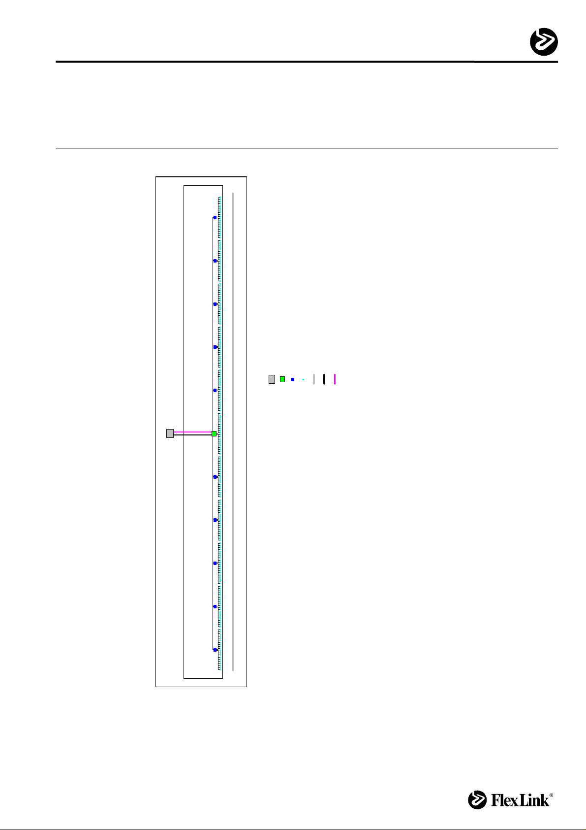
1. AGS-system layout
The AGS-system contains the following parts:
1. Control box;
2. Guide units;
3. Guide unit cables;
4. Junction box;
5. Zone supply cables.
The points 4 and 5 are used when the number of Guide units are higher than the Control
box itself can control.
The default distance between Guide units is 1 meter. This may be changed depending on
application.
See picture next page.
For more information see document "Controls overview".
2006-05-19
1.1 Integrator responsibility
Some parts of installation is application depending and part of the integrator’s
responsibility:
Archived
1. Box mounting frames;
2. Wire ways;
3. Zone supply conductors (see chapter “4. Zone supply”)
3928587_03.DOC
Page 3
Specification
Unit/Dept. Document type Date
APD/Research & Development
Issued by Document number Page Approved by
Assembly Instruction
Fredrik Johansson 3928587-03 3/12 FJn
2006-05-19
Conveyor system's control cabinet
Junction box
Control box
Guide unit
Conveyor
Power cable
Communication cable
Legend
Archived
AGS
Conveyor system
3928587_03.DOC
- 1 Control box
Data
- Max. 5 Junction boxes in both
directions
- Max. 10 Guide units in both
directions for each box
Page 4
Specification
Unit/Dept. Document type Date
APD/Research & Development
Issued by Document number Page Approved by
Assembly Instruction
Fredrik Johansson 3928587-03 4/12 FJn
2. Placing components
General information:
• The cable between Guide units is a factory-made cable with fixed length (2 or 3 m)
connectors in both ends which affects the placing of components.
• Maximum 5 Junction boxes can be connected in each direction from the Control
box.
• Maximum 10 or 6 (depending on cable length) Guide units can be connected in
each direction from Control box/Junction box.
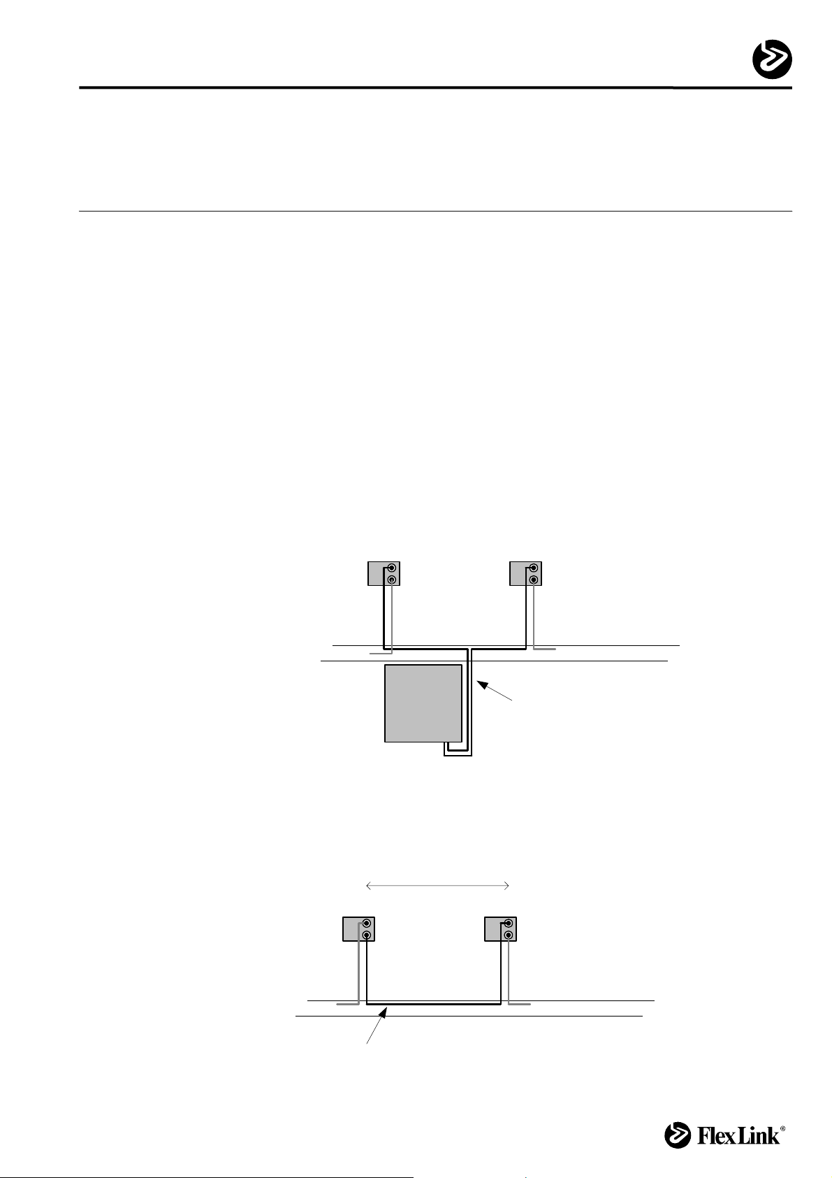
Instructions:
• Adjust the distance between the Control box or Junction box and the Guide unit so
that the Guide unit cable reaches between the Control box or Junction box and the
Guide unit.
2006-05-19
Guide unit
Wiring way
Box
Guide unit cable
Archived
• Place the Guide units so that the cable reaches between the Guide units.
Distance
Guide unit
Wiring way
Guide unit cable
3928587_03.DOC
Page 5

Specification
Unit/Dept. Document type Date
APD/Research & Development
Issued by Document number Page Approved by
Assembly Instruction
Fredrik Johansson 3928587-03 5/12 FJn
• The Control box and the Junction box are equipped with two horizontal XCBL 44
beams with T-slots attached to the backside. This makes it easy to mount the
Control box and the Junction box to other FlexLink structural beams.
2006-05-19
Archived
2.1 Using non-standard Guide unit cables
The standard length of Guide unit cable is 2 m for basic version and 3 m for heavy version.
If for any reason longer cables are required, the total cable length from the box to the last
Guide unit of that group is not allowed to exceed 20 meters.
Connectors for customized cable (Manufacturer Wieland):
• Female 96.031.4053.1 (screw connection)
• Male 96.032.4053.1 (screw connection)
For more information – www.gesis.com.
3928587_03.DOC
Page 6

Specification
Unit/Dept. Document type Date
APD/Research & Development
Issued by Document number Page Approved by
Assembly Instruction
Fredrik Johansson 3928587-03 6/12 FJn
3. Guide unit supply
The Guide unit cable is a factory-made cable with fixed length and connectors in both
ends.
The Control box, Junction box and the Guide unit are equipped with same type of
connectors.
WARNING! Disconnect electrical power by switching off the main switch of the Control box
before any electrical installation is started. Lock the switch with a padlock until the
installation is finished.
• Start by plugging the Guide unit cable into the Control box or Junction box,
thereafter into the Guide unit.
• Proceed by connecting the rest of Guide units controlled by the same Control or
Junction box.
Guide unit
2006-05-19
3.1 Connectors
Box
1. 2. 3.
Archived
When connecting two connectors the catch must say "click". The Guide units otherwise
risk to malfunction.
For disconnection see picture below.
3928587_03.DOC
Page 7

Specification
Unit/Dept. Document type Date
APD/Research & Development
Issued by Document number Page Approved by
Assembly Instruction
Fredrik Johansson 3928587-03 7/12 FJn
4. Zone supply
Up to five Junction boxes can be connected in both directions from a Control box.
The Zone supply conductor runs from the Control box and through the Junction boxes.
The conductor cable area must be 2.5mm
Zone supply conductor and wiring way.
Note: Preferably U.I. Lapp, Ölflex 110, 5G2.5, 1119 405, is selected for european
installations.
WARNING! Disconnect electrical power by switching off the main switch of the Control box
before any electrical installation is started. Lock the switch with a padlock until the
installation is finished.
• Run the conductor from the Control box and connect it to nearest Junction box.
• Continue to run conductors between the rest of Junction boxes.
2
. The integrator is responsible for the choice of
2006-05-19
Cable area = 2.5mm
Archived
Junction boxControl box
2
3928587_03.DOC
Page 8

Specification
Unit/Dept. Document type Date
APD/Research & Development
Issued by Document number Page Approved by
Assembly Instruction
Fredrik Johansson 3928587-03 8/12 FJn
European installation
2006-05-19
Archived
3928587_03.DOC
Page 9

Specification
Unit/Dept. Document type Date
APD/Research & Development
Issued by Document number Page Approved by
Assembly Instruction
Fredrik Johansson 3928587-03 9/12 FJn
US installation
2006-05-19
Archived
3928587_03.DOC
Page 10

Specification
Unit/Dept. Document type Date
APD/Research & Development
Issued by Document number Page Approved by
Assembly Instruction
Fredrik Johansson 3928587-03 10/12 FJn
5. Safety information
It is important to secure that products on the conveyor can not fall down on personal and
cause personal injury. Fall protection may need to be added below the conveyor. This is
specifically important where conveyors are running overhead a gangway. There is a risk
that the customer runs the system adjusted for the wrong product, this might increase the
risk of falling products. It is the integrators responsibility to install protections.
6. Installing the guide rail to the Guide units
Attach all Guide units to the conveyor. It is very important that the Guide units are parallel
to each other (see picture below). A and B must be equal.
Check that all Guide units are in outer position, this is the way they are delivered. Install
the guide rails adjusted for the widest product.
When the power supply is installed, run the system in and out and check that everything
runs smooth. Built in tensions can stop the system.
If a curve is made of segments placed at the same level it is important that the ends of the
segments never comes in contact with each other (see picture below). Check the whole
stroke of the guide unit!
Archived
A
B
2006-05-19
AA>0
3928587_03.DOC
Page 11

Specification
Unit/Dept. Document type Date
APD/Research & Development
Issued by Document number Page Approved by
Assembly Instruction
Fredrik Johansson 3928587-03 11/12 FJn
7. Feedback functionality – Track width setting
2006-05-19
7.1 System overview
The home position sensor (1) and the pulse sensor (2) shall be connected to the field bus
interface in the Control box with a cable (not included in delivery). The cable must have M8
3-pin connector towards the sensors.
The pulse sensor (2) is a magnetic sensor that counts pulses while the screw (3) is
rotating. The home position sensor (1) is a inductive sensor that detects when the sliding
element (4) is in end position.
7.2 Synchronization
If, by any reason the Guide units in a line are in different positions the line has to be
synchronized. When the command “synchronize” is chosen the unit starts to move out.
After reaching the home position sensor (1) the unit continues to move another 20
seconds*. If needed repeat this sequence until all Guide units are in outer position.
*The Guide unit can run against mechanical stop. This will make a humming sound but will
not damage the motor inside.
Archived
For controls information see document "Software user guide".
3928587_03.DOC
Page 12

Specification
Unit/Dept. Document type Date
APD/Research & Development
Issued by Document number Page Approved by
Assembly Instruction
Fredrik Johansson 3928587-03 12/12 FJn
8. Fault handling
No. Error description Check Possible reasons Action
1 Guide unit not moving a. Check automatic fuses
b. Check relay One relay should pull when running.
c. Total cable length Cable length too long. The total cable length from box through Guide units is not allowed to
d. Number of Guide units connected The total number of Guide units should not exceed 10 in each
e. Are the guide rails attached to the
Guide units without any stress?
2 Guide unit moving the wrong direction a. Connectors Loose Guide unit connector Secure that connectors are connected correctly.
Conveyor not horizontal.
Guide units not parallell to each
other.
2006-05-19
exceed 20 meters.
direction.
Check conveyor with water level.
Check Guide units with scale and composing stick.
Archived
3928587_03.DOC
 Loading...