

Page 1

FLEXLAN
IEEE802.11n/a/b/g
Access Point
FXA2000-G
User’s Manual
CONTEC CO.,LTD.
Page 2
-
-
-
-
-
-
-
-
S
etup
Gu
ide
FXA
-2000-G
Tapp
ing
screws
M
agne
t
Check Y our Package
Thank you for purchasing the CONTEC product.
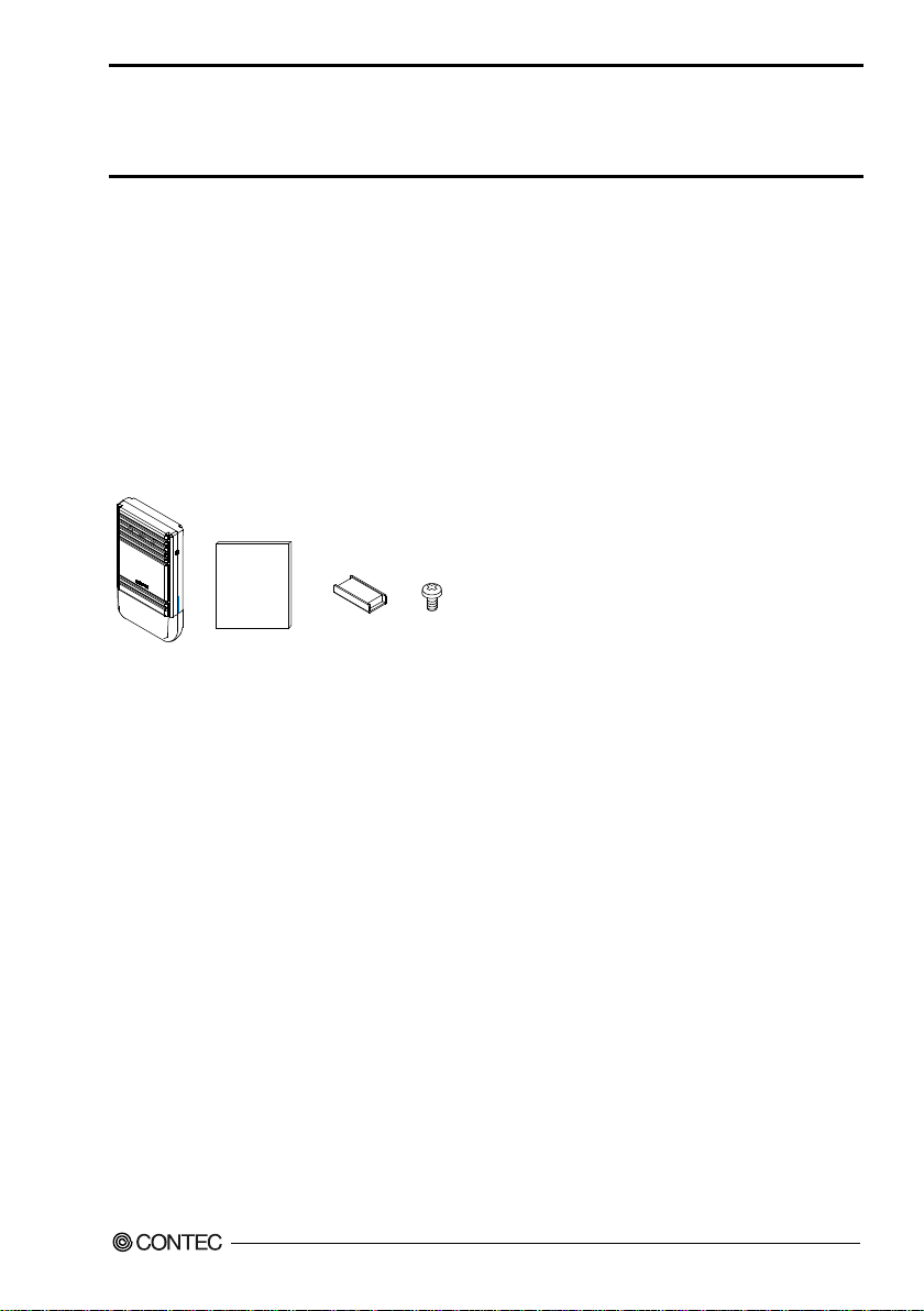
The product con s i sts of the it e m s lis ted belo w.
Check, with the following list, that your package is complete. If you discover damaged or missing items,
contact your retailer.
Packin g List
Main unit (FXA2000-G)...1
Setup Guide (English)...1
Setup Guide (China)...1
Setup Guide (Korea)...1
* You ar e free t o download t he manual of this product from the Cont ec’s website (http://www.contec.com/).
Setup Guide (Taiwan). ..1
Magnet...2
Tapping screws...2
Connector cover (Installed in unit)...1
FXA2000-G
i
Page 3
Full term
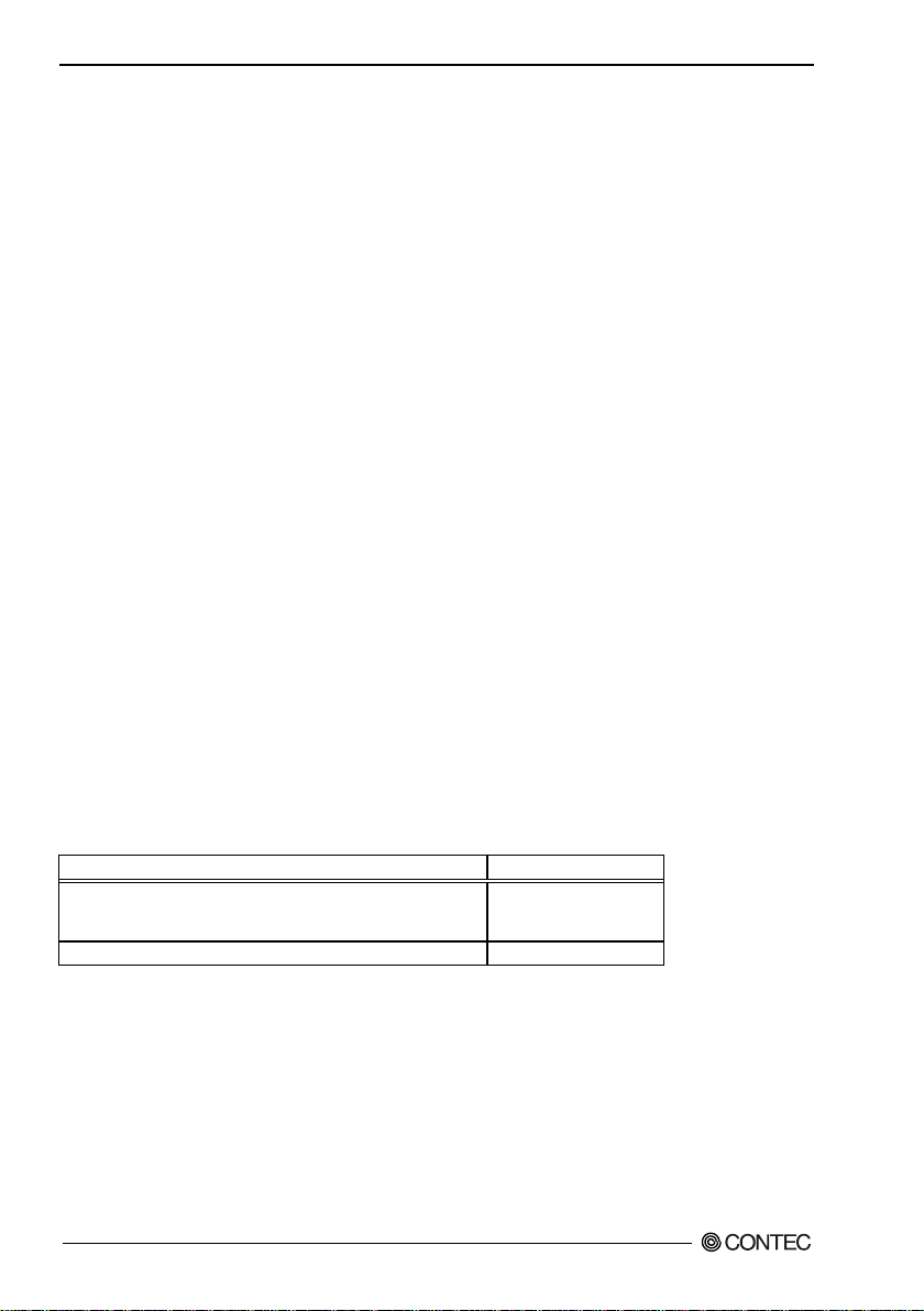
Term used in this manual
AP
ST
Personal compute r
PC
Copyright
Copyright 2013 CONTEC CO., LTD. ALL RIGHTS RESERVED.
No part o f th i s do cument ma y b e c opied or reproduc ed i n an y form by any m ea n s w ithout pr ior writt en
consent of CONTEC CO., LTD.
CONTEC CO ., LTD. makes no commitment to update or keep current the information cont ained in this
document.
The information in this document is subject to change without notice.
All relevant issues have been considered in the preparation of this document. Should you notice an
omission or any questionable item in this document, please feel free to notify CONTEC CO., LTD.
Regardless of th e foregoing statem ent, CONTEC assumes no responsibility for any er r ors that may appear
in this document or for results obtained by the user as a result of using this product.
Trademarks
FLEXLAN is a registered trademark or trademark of CONTEC CO., LTD.
MS, Micros oft, Windows, are reg istered trademarks or trademarks of Microsoft Corporation in the U .S.A.
and oth er countries.
Netscape, Netscape Navigator is a regist ered trademark of Netscape Communicatio ns.
Other nam e s of companies and products used in this document tra de marks or r egistered trademar ks of the
related companies. This document does not use the symbols ™, ®, © etc.
Terminology/Abbreviations
The following terms and abbreviations are used in this manual for convenience.
Access point
Station
/Wireless terminal
About the speed mark
The link speed shown fo r the transmission ra te in this manual, the set up s creens, an d elsewhere is the
theoretical maximum value based on the wireless LAN standard and does not represent the actual data
transfer rate.
FXA2000-G
ii
Page 4

Table of Contents
Check Your Package .................................................................................................................................... i
Copyright ...................................................................................................................................................... ii
Trademarks ................................................................................................................................................... ii
About the sp e e d ma r k ........................................................................................................................... ii
Table o f Content s ........................................................................................................................................ iii
1. INTRODUCTION 1
About the FXA2000-G ................................................................................................................................ 1
Features ................................................................................................................................................. 1
Customer Support ........................................................................................................................................ 3
Web Sit e ................................................................................................................................................ 3
Limited One-Year Warranty ....................................................................................................................... 3
How to Obtain Service ................................................................................................................................ 3
Liability ........................................................................................................................................................ 3
Safety Pr ecautions ....................................................................................................................................... 4
Safety Information................................................................................................................................ 4
Usage limitation.................................................................................................................................... 4
Precautions Related to Service ............................................................................................................ 4
About the sp e e d ma r k ........................................................................................................................... 4
Notes on Radio Inte rface ..................................................................................................................... 5
Security Precautions ............................................................................................................................. 6
Handling Precautions ........................................................................................................................... 6
Federal Communications Commission ............................................................................................... 8
Environment ......................................................................................................................................... 9
Inspection .............................................................................................................................................. 9
Storage .................................................................................................................................................. 9
Disposal................................................................................................................................................. 9
2. SETUP 11
Compone nt Locat ions ................................................................................................................................ 11
LED display ........................................................................................................................................ 11
INIT switches ..................................................................................................................................... 11
Chec king the Network Addre s ses ............................................................................................................. 12
Power Supply ............................................................................................................................................. 13
When using the AC adapter (FX-AC052) ........................................................................................ 13
When supplying power from the power connector .......................................................................... 13
When supplying power from the LAN ca ble.................................................................................... 14
Installation .................................................................................................................................................. 15
Preparation before Installation........................................................................................................... 15
Using magnet s for insta llation ........................................................................................................... 16
FXA2000-G
iii
Page 5

Using the include d scr e ws for insta lla ti on ........................................................................................ 16
DFS function ...................................................................................................................................... 17
DFS function ...................................................................................................................................... 17
3. CONNECTION TO DEVICES AND SETUP METHODS 19
Prepar a tion before Setup ........................................................................................................................... 19
Setup Usi ng a Web Browser ..................................................................................................................... 21
Settin g the Browser ............................................................................................................................ 21
Connec ting to This Product Using Web Browser ............................................................................ 24
4. SETUP AND STATUS DISPLAY 25
Basic settings ............................................................................................................................................. 25
System ................................................................................................................................................. 25
Radio ................................................................................................................................................... 26
VAP ..................................................................................................................................................... 28
Advan ce d Settin g s ..................................................................................................................................... 32
System ................................................................................................................................................. 32
Ethernet ............................................................................................................................................... 33
VAP ..................................................................................................................................................... 35
SNMP .................................................................................................................................................. 40
Network Time ..................................................................................................................................... 42
VLAN ................................................................................................................................................. 43
Log ...................................................................................................................................................... 45
Status Display ............................................................................................................................................ 46
System ................................................................................................................................................. 46
WLAN................................................................................................................................................. 47
MAC Address Table .......................................................................................................................... 51
Log Information ................................................................................................................................. 52
Maintenance........................................................................................................................................ 55
5. WIRELESS LINK MODE AND WIRELESS LAN FUNCTION 59
Wireless Link Mode .................................................................................................................................. 59
Standa r d Infrastructure Mode ............................................................................................................ 59
Compatible Inf rastr ucture Mode ....................................................................................................... 60
Advanced Infrastructure Mode .......................................................................................................... 61
Repeater ...................................................................................................................................................... 62
What’s Repeater? ............................................................................................................................... 62
Specification for Repeater and Wirele s s Connection Mode ............................................................ 62
Recommended S etting ....................................................................................................................... 63
Notes ................................................................................................................................................... 64
Installation in a Network ........................................................................................................................... 65
Featu res of th e W i reles s N etwork ..................................................................................................... 65
Operating Environment and Radio Waves ....................................................................................... 66
FXA2000-G
iv
Page 6
Constr uc ting a Network ..................................................................................................................... 68
6. MAINTENANCE 71
Maintenance Tool ...................................................................................................................................... 71
Log File Collection .................................................................................................................................... 71
Using FTP to Get the Log File .......................................................................................................... 72
Sav in g the Sett ings File ............................................................................................................................. 73
Using FTP to Backup the Settings Fi le ............................................................................................. 73
Restoring the Sof tware Settings ................................................................................................................ 74
Using FTP to Res tore the Set tings .................................................................................................... 74
Upgrading the Firmware ........................................................................................................................... 75
Performing an Upgrade Using FTP ................................................................................................... 75
Initialization ............................................................................................................................................... 76
Using a Web Browser ........................................................................................................................ 76
Using the INIT Switch of the Main Uni t .......................................................................................... 76
7. TROUBLESHOOTING 77
When Communication Fails...................................................................................................................... 77
Setu p Screen Unavailable on Web Browser ............................................................................................ 78
When the AP Will Not Start ..................................................................................................................... 78
8. APPENDIX 79
Factory Default S ett in g s List .................................................................................................................... 79
9. SPECIFICATIONS 97
Envir on m e nt a l Specifications ............................................................................................................ 98
External Dimensions.................................................................................................................................. 99
I/O Interface ............................................................................................................................................. 100
FXA2000-G
v
Page 7

FXA2000-G
vi
Page 8

1. Introduction
1. Introduction
This chapter provides information you should know before using the product.
About the FXA2000-G
The FXA2000-G is an access poin t th a t confo rms to IEEE 802.11n/a/b/g wireless networking standards
and th at supports a wide range of input power (5 to 30 VDC) and PoE .
Light weig ht and compact design enables a smart installation with included magnets and tapping screws.
Compatible to setting both as access point and station. This produc t can be used as a Wireles s LAN
converter for wired LAN devices.
This product is supported with a connector protection cover and a security slot for theft proof.
Features
- Compatible wi th 4 standards, IEEE802.11n/a/b/g
You can choose 24 ch (W52/W53/W56/ W58*1) in th e 5 G Hz (IEEE802.11n/a), and in the 2.4 GHz
(IEEE 802.11n/g), you can choose from 1 to 11ch. So , it is possible to design a flexible wireless network
to adjust a radio wave interference.
- Light wei g ht and compact design for in sta l la tion set ting and s op histica te d a ppearan c e
Compatible wi th PoE and inc lude an antennae inside chassis considering installation setting and
sophisticated appearanc e. This product can be used at variety of setting us ing included magnets and
tappin g s crews.
- Supports a various power supply
This product support a various power supply, such as AC adapter, DC power from 5 to 30 VDC, and PoE.
- Compatibl e with switching between a cc ess point and station
This product is compatible to setting both as a station access point (a base station) and a station (a client
station) by changing the mode and used as Wireless LAN converter for w ired LA N devices.
- The proprietar y encryption technology "WSL" that is avai lable along with WPA2/WPA and WEP.
This product supports an sophisticated security standard "WPA2/WPA", "IEEE 802.1X authentication",
"MAC address filtering" and ""ESSID hide". In the addition, it also supports the proprietary encryption
technology "WSL" that is available along with WPA2/WPA and WEP.
- Features variety of functions, including VLAN and a virtual AP function
This product has a virtual AP function that allows operating VLA N function and an AP as a multi-AP,
and configuring the settings for different security. Furthermore, this product can store a large event log
capacit y (Conventional ratio: seven times, Approx: 15,000 logs) .
FXA2000-G
1
Page 9

1. Introduction
- Supported wit h a c on nector pr otectio n c ov er and secu r i t y wire conn e ction con figuration
This pr o du ct can be pr ot ec t e d f rom theft by protecting con n e ct o rs with included co nnector c over and
attac hing a securi ty wire to s e cu r ity slot.
*1 USA (FCC) : W52: 36, 40, 44, 48ch / W53: 52, 56, 60, 64ch / W56: 100, 104, 108, 112, 116, 132, 136, 140ch / W58: 149,
153, 157, 161, 165ch
FXA2000-G
2
Page 10

1. Introduction
Customer Support
CONT EC pr o vides the f ollowing su p port services for you to use CO NTEC products more effici ently and
comfortably.
Web Site
Japanese http://www.contec.co.jp/
English http://www.contec.com/
Chinese http://www.contec.com.cn/
Latest product information
CONTEC provides up-to-date information on products.
CONTEC also provides product manuals and various technical documents in the PDF.
Free download
You can d ownload update d driver software an d differe nti a l files as wel l as sample prog rams available in
several languages.
Note! For product information
Contact your retailer if you have any technical question about a CONTEC product or need its price,
del ivery time, or estimate inf ormation.
Limited One-Year War ranty
CONTEC products are warranted by C ON TEC CO., LTD. to be free from defects in mate rial and
workmanship f or up t o on e y ea r fr om the dat e o f pur c hase by the or iginal pu r c ha s er.
Repair will be fr ee of charge only when this device i s returned freight prepaid with a copy of the original
invoice and a Return Merchandise Authorization to the distributor or the CONTEC group office, from
which it was purchased.
This wa rr a nty is not ap plicabl e f or s cr a t ches or nor ma l wear, bu t only for the electr onic circu i try and
origi na l pro ducts. T h e warrant y is not appl i cable if th e de vice has be e n t a m pered wit h or damaged
throu g h abuse, mi streatm en t, n eg l e c t, or u nr easona bl e use, or if th e or i ginal invoice is no t include d, i n
which case repairs will be consider ed beyond the warra nt y policy.
How to Obtain Service
For replacement or repair, return the device freight prepaid, with a copy of the original invoice. Please
obtain a Return Merchandise A uthorization number (RMA) from the C O N TEC group office where you
purchased bef ore returning any product.
* No pr o duct will be accept ed by CONT EC group wit hout the RMA number .
Liability
The obligation of the warr a n t or is solel y to r e pa ir or repla ce the product. In no eve nt w il l t h e wa rr antor
be liable for any incidental or consequential damages due to such defect or consequences that arise from
inexperienced usage, misuse, or malfunction of this device.
FXA2000-G
3
Page 11
1. Introduction
DA
NGE
R
WARNING
CAUTION
Safety Precautio ns
Underst a nd the following definitions and precautions to use the product safely.
Safety Information
This doc ument provides safety informat ion using th e f ollowing symbols to prevent accidents resulting in
injury or de ath and the destruction of equipment and resour ce s. Understand the meanings of these labels
to opera t e the equip m ent safely.
DAN GER indicates an imminen t ly ha za rdous si tuation w hich, if not a vo i d e d, w i ll
result i n dea th or serious injury.
WARNING indicates a potentially hazardous situation which, if not avoided, could
result i n dea th or serious injury.
CAUTION indi cates a potentially hazardous situation which, if not avoided, may result
in minor or m oderate i nju r y or in property da ma ge.
Usage limitation
This product has not been developed or manufactured to be used in systems including the equipment
which is directly related to human lives *1 or the equipment which involves human safety and may
signifi cantly affect the maintenance of public functions *2. Therefore, do not use the product for such
purpose s . In addition, do not use the product with in 20cm from a human body on a regular bas is.
*1: Medical devices such as life-support equipment and devices used in an operat ing theater.
*2: Main control systems at nuclear power stations, safety maintenance systems at nuclear facilities, other
important sa fet y -related systems, op er a tion cont r ol system s within group transp or t system s , air-traffic
contr o l syste m s , etc.
If using the IEEE802.11a standard, ensure that you comply with all relev ant laws in th e c ountry of
use.
Precautions Related to S ervice
Clean t hi s pr o du ct by wipin g l ig htly wit h a soft cloth moistened with wat er or a cleaning solution.
Tak e care t o av oi d t h e u s e o f b en z e n e, thinner s or other vola t i l e s ol u tions which may cause deformatio n
or disco l oration.
About the speed mark
The link speed shown for the transmission rate in this manual, the setup screens, and elsewhere is the theoretical maximum value based on the wireless LAN standard
and does not represent the actual data transfer r ate.
FXA2000-G
4
Page 12

1. Introduction
Notes on Radio Interface
The 2.4 GHz band used by this product covers the operating frequencies of mobile-identification local
radio stations (requiring th e license), specific low-power radio stations (requiring no license) and amateur
wireless stati ons (requir in g th e lic ens e) as well a s indus tria l , sci entific, and medical equi pm ent suc h as
microwave ovens.
1. Before using this product, make sure that there is no mobile-identification lo cal radio station, sp ecific
low-power radio station and amateur wi reless sta tion operating near the product.
2. If the product should cause radio interface with any mobile-identification local radio station or
specific low-power radio station, immediately change the operating frequency to avoid the radio
interface.
3. Plac ing wir eless termina l s near each oth er may slo w s do w n their da t a ra te beca use of th ei r mutu a l
interference. You should allow a minimum clearance of about 1m between stati ons, 3m between
access point and station, and 3m between access points.
4. Contact yo ur loc al retailer or CONTEC if the product has trouble s uch as rec ur r ent radio interface
with mobile-identificat io n local r adi o sta tio n s or speci fic low-power radio stations
FXA2000-G
5
Page 13

1. Introduction
DANGER
Security Precautions
Wireless LAN uses radio waves ins tead of LAN cables to send and receive dat a between a computer and
a wireless access point, m akin g i t possible to freely establ ish a LAN connec tion within a range of the
radio waves. However, radio waves can be received through obstacles, su ch as walls, when within t he
range. Therefore, if security settings are not ma de, the fol lowing problems may occur. Unauthorized
viewing of data An unauthorized third party can intercept the radio waves and view e-mail messages and
personal information, such as user ID and password or your credit card information. Unauthorized access
An unauthorized third party can access a personal or corporate network and cause the following damage:
- Intercepting personal info rmation and confidential information (inf ormation leak)
- Usin g a false identity to communicate and disclose in formation illegall y (identity theft)
- Changing and transmitting intercepted data (tampering)
- Damaging data and systems by spre a ding a computer virus (destruction)
The wire l e s s LAN card and wireless a c ce s s point have secu r ity feat u r e s to cou nter thes e problem s . U si n g
the security settings of the wireless LAN equipment can help prevent these problems from occurring. The
securi ty sett ings of the wireless LAN equipment ar e not configured at the t ime of purchase.
To reduc e securit y problem s , c onfigur e all securi t y se ttings of the wirele s s L AN e qu ipment a c c or d ing to
the manual before using the wireless LAN card and wireless acces s point. Please be aware that the
secur ity settin gs do not pro vide complete se cu ri t y protect i on due to wir eless LAN sp e ci f ication s. I f y ou
are unable to configure the security settings yourself, please contact your local author ized dealer . The
customer is resp onsible for configuring the security settings and understanding the risks inherent in using
the product without the security settings configured.
Handling Precautions
Do not use the product where it is exposed to f lammable or corrosive gas. Doing so may result in an
explosi on, fire, el ectric shock, or failure.
FXA2000-G
6
Page 14

1. Introduction
CAUTION
- This product contains precision electronic elements and must not be used in locatio ns subject to
physi ca l s h ock or stron g vi br a t i on. Other wise, the board may malfunction, overheat, or cause a
failure.
- Do not use or store this device i n high temperature or low t emperature surroundings, or do not expose
it to extreme tem perature changes. Otherwise, the bo ard may malfunction, overheat, or cause a
failure.
- Do not use or store this device where it is exposed to direct sunlight or near stoves or other sources of
heat. O t h erwise, the boa rd may malfun ction, overh ea t, or cause a fai lure.
- Do not use or store this device near strong magnetic fi elds or devices e mitting elect romag netic
radiation. O therwise, the bo a rd may malf unction, overheat, or ca us e a fail ure.
- If an unusual smell or overheat is noticed, unplug the power cable immediately In the even t of an
abnor ma l c on dition or ma lfunction, plea s e co ntact your retailer.
- The sp ecificati ons of this product are subject to chan g e w it h ou t n otice for e n ha n c e me nt and qua lity
improvement. Even when using the product continuously, be sure t o read the ma nual and understand
the cont e nts.
- Do not bl ock t h e v e nt ilation holes by placing objects on the produc
- Do not attempt to modify this device. The manufacturer will bear no responsibility whatsoever for
the devi c e if it has bee n m odified .
- The product mu st a l wa y s b e a s s oc iated wit h t h e s etu p guide.
- Regardless of the foregoing statements, CONTEC is not liable for any damages whatsoever
(incl uding damages for loss of business profits) arising out of the use or inabil ity to use this
CONTEC p roduct or the informatio n contained herein.
FXA2000-G
7
Page 15

1. Introduction
Federal Communications Commission
This equ ipment ha s b e en te sted and fou n d t o co m ply with the l i mi t s f or a C lass A digi t a l de vice, pursuant
to part 15 of the FCC Rules. These limits are designed to pro-vide reasonable protection against harmful
interference when the equipment is opera te din a co m m ercial environment. This equipment generat es ,
uses, and can radiate radiofrequency energy and, if not installed and used in accordance with the
instruction manual, may cau se harmful interference to radio communications. Operation of this
equipment in a residential area is likely to cause harmful interference in which case the user will be
required to co r rect the interfer ence at his own expense.
If this equipment does cause harmful interference to radio or television reception, which can be
determined by turning the equipment off and on, the user is encouraged to try to correct the interference
by one of the following measures:
- Reorient or relocate the receiving antenna.
- Increase the separation between the equipment and receiver.
- Connect the equipment into an outlet on a circuit different from that to which the receiver is
connected.
- Consult the dealer or an experienced radio/TV technician for help.
FCC Caution: Any changes or modifications not expressly approved by the party r esponsible for
complia nce co uld void the us e r's authority to oper a te this equipment.
Operations in the 5.15-5.25GHz band are restricted to indoor usage only.
This device complies with part 15 of the FCC Rules. Operation i s subject t o the following two conditi ons:
(1) This device may not cause harmful interference, and
(2) This device must accept any interference received, including interference that may cause undesired
operation. Thi s tran s mitte r mus t not be co-lo ca ted or oper a t i n g i n c o njunctio n with any ot he r an tenna
or transmitter.
Radiation Exposure Statement: This equipment complies with FCC radiation exposure limits set forth for
an uncontrolled envir onment. This equipment should be installed and operated with minimum distance
20cm between the radiator & your body.
FXA2000-G
8
Page 16

1. Introduction
Environment
Use this product in the following environment. If used in an unauthorized environment, the board may
over h eat, mal function, or cause a fai l u re.
Operating temperature
0 - 40ºC
Humidity
10 - 90%RH (No condensation)
Corrosive gases
None
Floating dust parti cl e s
Not to be excessive
Inspection
Inspect the product periodically as follows to use it safely.
Storage
When storing this product, keep it in its original packing form.
(1) Put this produ ct i n the storage ba g .
(2) Wrap it in the packing material, and then put it in the box.
(3) Store the package at room temperature at a place free from direct su nlight, moisture, shock, vibration,
magn et ism, an d s tatic el ectricity.
Disposal
When disposing of the product, follow the disposal pr ocedures stipulated under the relevant laws and
municipal ordinances .
FXA2000-G
9
Page 17

1. Introduction
FXA2000-G
10
Page 18
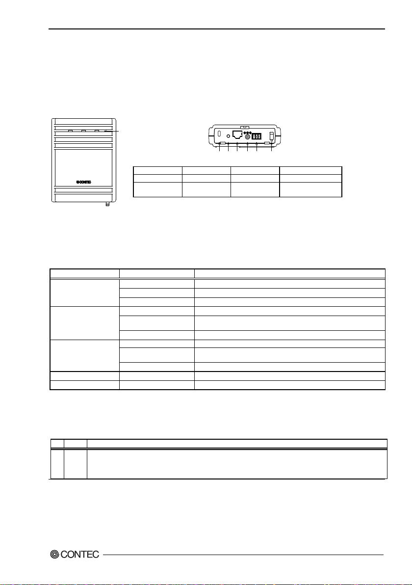
2. Setup
POWER
LANWLAN
LED
I
N
IT
5
VD
C
1
0
/1
00
M
LA
N
5-
30
V
DC
Vi
-
FG
Vi
+
(1)
(
2
) (
3)
(
4)
(5
)
(6
)
(1)
Security slot
(2)
INIT Switch
(3)
LAN port
(4)
DC JACK
Power disconnection
prevention hook
LED name
Status
Indicator
ON
Indicates that the device is operating.
Flashing
Indicates that the device is being started (This device turned on)
OFF
Indicates that the device is power off.
ON
Indicates that a wired LAN has been connecte d.
Indicates that the product is transmitting/receiving data to/from the
connected te rminal through wired LAN.
OFF
Indicates that a wired LAN not logged-in.
ON
Indicates that the device has been connected.
Indicates data is being transmitted to or received from the device
connected through wireless LAN.
OFF
Indicates that the device has been no connected.
POWER/ LAN/ WLAN
Flashing (simultaneously)
Indicates that firmware has been reprogrammed. *1
POWER/LAN
Blinking twice / On
DHCP error
No.
Name
Operation / function
1
INIT
Used to initialize this product (reset to factory default settings). When this switch is pressed, the POWER,
factory default when next started.
2. Setup
The antenna mu st be mounted and installed properly before confi guring this product. Follo w the setu p
procedure for the product shown below.
Component Locations
(5) Power connector
Figure 2.1. Front side
LED display
Table 2.1. LED display (at the time of n ormal operating)
POWER
LAN
WLAN
*1 Not include LogFile
Flashing
Flashing
INIT switches
Table 2.2. INIT switches
WLAN, and LAN LEDs start to flash. If this swit ch is released during the period from w hen the LEDs start
to flash and until they turn on (appr oximately 3 seconds), all of the access point's settings will be reset to the
(6)
* When initializing the product by turning the INIT signal on and off, the LEDs will continue flashing for a short time
after the signal is turned off. This indicates the internal memory files are being deleted. If the power is turned off while
the LEDs are flashing, the internal memory files may be damaged and the product may no longer be able to start properly.
Always restart the product after the LEDs stop flashing.
FXA2000-G
11
Page 19
2. Setup
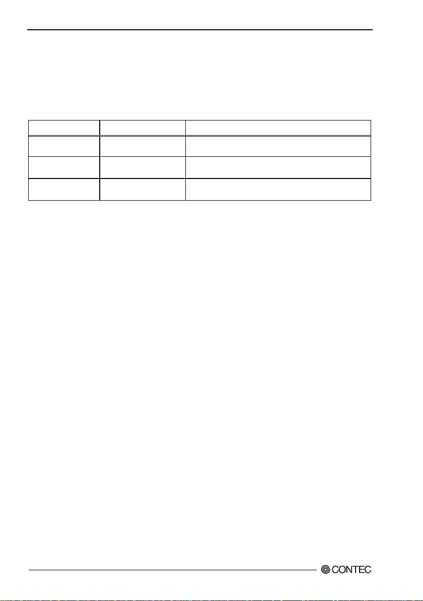
Description on the
housing sticker
Checking the Network Addresses
The Ethernet (wired LAN), wireless LAN MAC address and IP address are defined on the housing sticker
on the side of this product. Write down the MAC addresses for Ethernet and wireless LAN in the
following table as they are device-individual va lues and may be requi r e d f or future s etup.
Table 2.3. Network Ad dress
Explanation Address
IP: Default IP Address 192.168.0.1
LAN MAC: LAN MAC Address
WLAN MAC:
Wireless LAN MAC
Address
FXA2000-G
12
Page 20
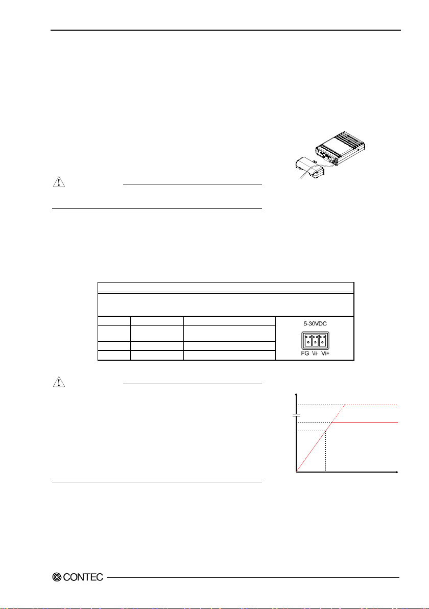
Power Supply
Pass the DC plug through the connector cover opening and
conne
You can prevent the DC plug from be i n g pu l l ed out by ho ok i n g
the cord on the power disconnection prevention hook located
on the co n ne ctor sect ion.
CAUTION
Function
Power connector: MC1,5/3-ST-3,5(PHOENIX CONTACT),
specifications)
Pin No.
Signal name
Meaning
Power supply
2
Vi-
Power supply (GND)
3
FG
Frame ground
CAUTION
-
- Input voltage r an ge: 5 to 30 VDC ± 5%. Use a power supp ly
-
In
put
voltag
e
Tim
e
(ms)
(
v)
30
5
4.75
10
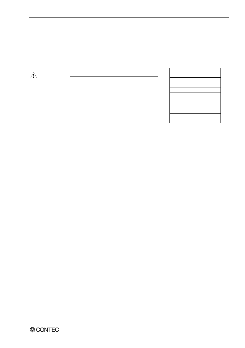
Figure 2.
Three wa ys for power supply of this product is shown in the followings.
When using the AC adapter (FX-AC052)
ct the AC adapter's DC plug to the product's DC jack.
When supplying power via PoE, do not use the power
Figure 2.2. Power Suppl y Connectior
suppli ed from the power connector or the AC adapter.
When supplying power from the power connector
Power can be externally supplied using the power connector. Use the components indicated to the
followings for the power cabl e or use equivalent component s.
Table 2.4. Power connector
Cable: AWG28-16(on the condition that the cable length satisfies the power
2. Setup
1 Vi+
Carefu l ly manu facture the po w er cabl e t a k i ng care n ot to
mistake the wiring. In particular, if the power cable is used
with mistaken housing pin numbers, there is a risk of
malfunction or accidents.
that ris e s to 4.75 VDC or higher in the input voltage range
within 10 ms. There is a risk of damage to the device or
accid e nt if a power su p ply outsi de t his range i s used.
When sup plying po w er w i t h t h e AC adapter, d o not use
power supplied from t he power connector.
FXA2000-G
(5 to 30 VDC ±5%)
3. Power Su pply Time
13
Page 21
2. Setup
POW-CB50AF
HUB
FXA2000
CAUTION
When supplying power from the LAN cable
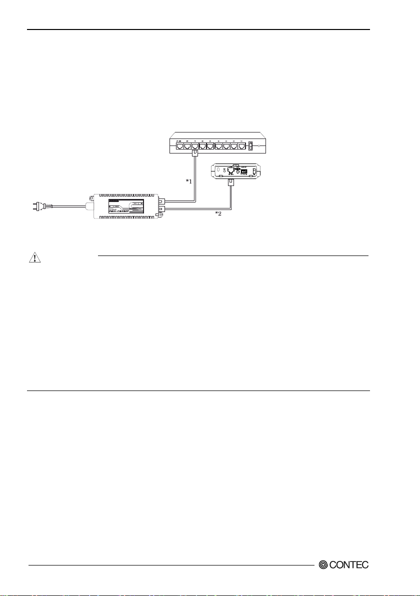
The F X A20000-G can b e power-supplied through a LAN cable from an IEEE802.3af-compliant power
supply unit.
For details, ref er to the power supply un it .
The fol lowing gives an example of connection
Figure 2.4 . Power Supply Connection
- The ove rall length of the LAN cable between the power supply destination and the hub must be up to
100 m.Route the cabling such th a t ( 1) + (2) is 100 (m) or less.
- Do not connect the output LAN cable to any IEEE 802.3af non-compliant device as doing so can
caus e d evice fa ults or a cciden ts.
- When supplying power to the unit via the LAN cable, do not use the bundled AC adapter an d d o no t
touch the power jack position.
- Do not connect an AC adapter other than the bundled one as doing so can cause device faults or
accidents.
- Once the unit has been powered with the AC adapter, do not turn the DC plug or vibrat e th e AC
adapter.
FXA2000-G
14
Page 22
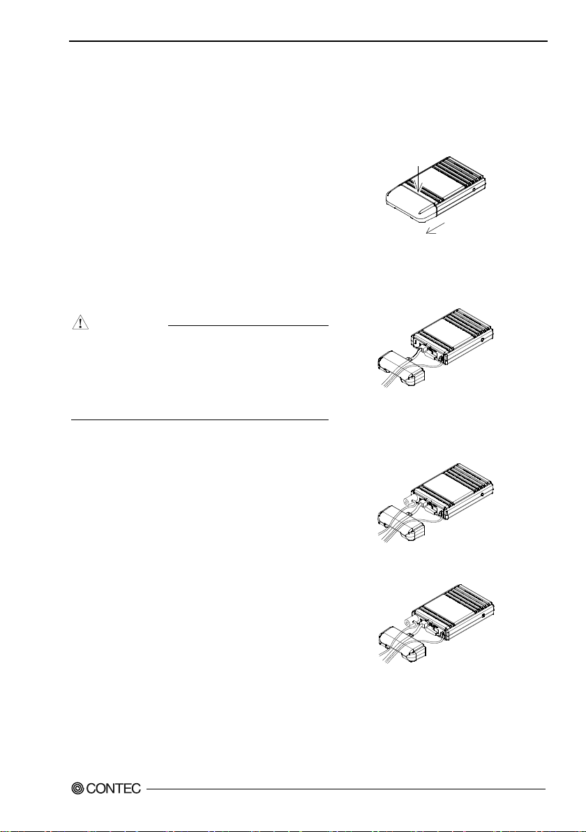
Installation
Removing the connector cover
While lightly pushing vertically on the center of the
connector cove r [(1) in th
cover [(2) in the diagram], and remove the connector
cover.
(1)
(2)
LAN
Connect a LAN cable to this product's LAN port.
CAUTION
-
-
Attaching the security wire
A commercially ava
to the se cu r ity slot loca ted on th e co n nector se c ti o n.
Recommended security wires:
SUPPLY SL
Attaching the connector cover
Attach
Read and understand the following precautions before installation :
Preparation before Installation
e diagram], slide the entire
2. Setup
Port
Ensure that the cable length be twee n this product
and a PC or hub is 100 m or shorter.
When su p plying po w er vi a P oE or when using
100BASE-TX, use a Category 5 or better cable.
When usi ng 10BASE-T, use a Category 3 o r better
cable.
ilable security wire can be attached
KOKUYO EAS-L41, Buffalo BSL4D S, SANWA
-31S
the connect or cover to the product.
Figure 2.5. Removing the connect or cove r
Figure 2.6. Connect LAN Cable
Figure 2.7. Attaching the security wire
FXA2000-G
Figure 2.8. Attaching the connector cover
15
Page 23
2. Setup
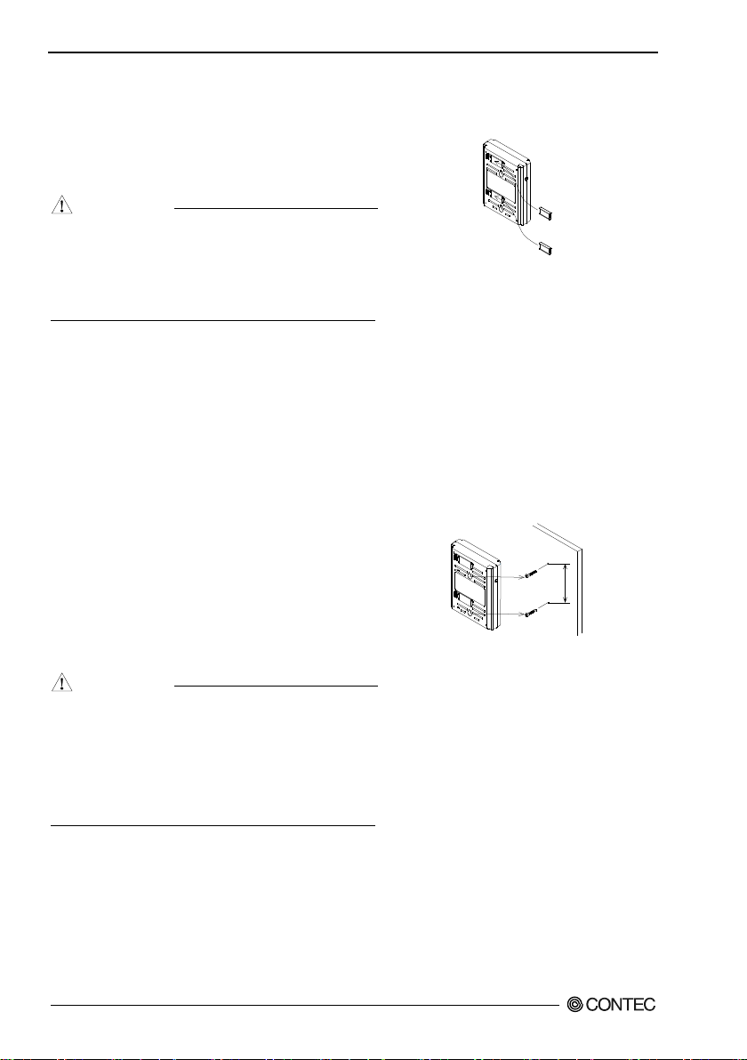
Using magnets for installation
Attach the included magnets to the two magnet
attachm e nt locations on the back of the access point. To
attach the magnets, push them in the di
arrow to inser t them entirely into the attachment holes.
CA
UT
I
ON
-
-
Using the included screws for installation
Referring to the diagram to the right, drive the two
included scre w s into a sturd y, vert ical wall surface while
leaving around 3 mm of the screws st icking o
wall surface.
Hook the attachment holes on the bac k of the acces s
point to the heads of the sc rews to attach it.
Due to the characteristics of wirele ss networ ks, the
signal wi ll spread in a wider area when the access point
is installed in a hig
recommend you install it in a loca tion as hi gh as
possible.
Note t ha t t h e pl acin g t h e p r o duct near meta l or c oncret e
walls (including steel beams) may cause the signal
quality to degrade.
CAUTION
-
-
[mm]
80±0.2
rection of the
Do not pla ce the magnets near items that are
susceptible to magn eti c field s .
If the product is moved while attached to a steel
desk or other object , it may damage th e pa i n ted
surface.
ut from the
Figure 2.9. Using magnets for installation
hly-visib le loca tio n, so we
The access point cannot be installed on the ceiling
using the s crews due to the danger of falling. If a
ceiling installation is required, use the optional
installation bracket.
Caution: If the product's ventilation holes are
blocked, the product may malfunction due to a rise
in inter na l temperature.
FXA2000-G
16
Figure 2.10. Using the included screws for
installation
Page 24
DFS function
DFS function
When set to DFS-supported ch annels (5 GHz only), if rad a r waves are
detected, the channel must be changed in order to avoid radio wave
interfere n c e w i th
following.
CAUTION
-
-
-
-
DFS
W52: 36, 40, 44, 48
Not
supported
W53: 52, 56, 60, 64
Effective
W56: 100, 104, 108,
Effective
W58: 149, 153, 157,
Not
supported
2. Setup
weather radars and oth er radars, so note the
After starting, the channel is checked for radar waves for one
minute, so at a minimum, one minute or longer is required.
If radar waves are detected during startup or while started, the
access point may sta r t on anoth er channel since it must use a
chan nel dif ferent from the s et chan n el.
Eve n after starting with the set DFS-supported channel, the
channel may change while running.
If radar waves are detected, the radio waves must stop for 30
minutes , so the detected channel cannot be used fo r 30 minute s .
DFS-supporte d channel
(Frequency: 5GHz)
Channel
112, 116, 120,
124, 128, 132,
136, 140
161, 165
function
FXA2000-G
17
Page 25

2. Setup
FXA2000-G
18
Page 26

3. Connecti on to Devices and Setup Methods
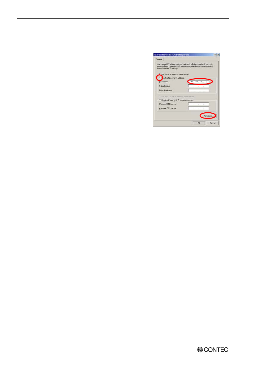
(1) Click [Start] (or the Windows logo button) - [Co ntr ol Pan el] - [Network and Internet] - [Network and
(3) Select the "Internet Protocol Version 4 (TCP/IPv4)" check box, and click "Properties".
(4) In the "Use the following IP address" field , type an IP a ddress 192.168.0.XXX, which is not the
3. Connection to Devices and Setup
Methods
This product is set up via a network using a Web browser or TELNET. Follow the setup procedure
below once the product is set up.
Preparation before Setup
You must use a PC which can be connected to a network as the product is set up via the network.
The setup is perf ormed by connecti ng a PC f or s etup purp oses and th e n us ing a Web bro w s er or
TELNET.
Connectin g for the fir st ti me
(1) Connect this product to PC on a wired L AN.
(2) Select an IP address 192.168.0.XXX (e.g. 192.168.0.10) for the PC, which is not the same address as
for this product. And the n s et the subnet mask to 255.255.255.0
* The default setting IPaddress is 192.168.0.1.
The foll owing exa mple settings are for Windows 7, Wi ndows Vista, or Windows XP using Internet
Explore r 7.0.
Windows 7 / W indows Vista
Sharing Center] - [Change adapter settings], and then right-click the icon f or the loca l area
connection to open up the [Properties ] screen.
(2) If a User A c count Control window appea rs, click "Y e s " or "Continue".
same add ress as this product (e.g. 192.168.0.10), and then set the subnet mask to 255.255.255.0.
(5) Click "OK", and then click "OK" or "Close" to enable the settings.
FXA2000-G
19
Page 27
3. Connecti on to Devices and Setup Methods
(1) Click [Start] - [Control Panel] - [Network Connection], and then right-click the icon for local area
(2) In the "Use the following IP address" field , type an IP a ddress
Windows XP
connection to open up the [Properties ] screen.
192.168.0.XXX, which is not the same address as this product
(e.g. 192. 168.0.10), and then set the s ubnet mask to
255.255.255.0.
(3) Click "OK", and then click "OK" or "Close" to enable the
settings.
Changing the settings
(1) Connect this product to PC o n a w i re d LAN.
(2) Set the netw ork address of the PC to the s ame networ k address as for this prod uct.
FXA2000-G
20
Page 28
3. Connecti on to Devices and Setup Methods
Setup Using a Web Browser
Start up a Web browser and enter the IP address of this product after “http : //” in the address bar.
If connecting for th e fir st ti me, ent er th e defau lt IP a ddre ss. When the default setting IPaddress is
192.168.0.1, enter as follows.
http://192.168.0.1/
Enable the JavaScript function in the browser settin g a s it is used.
Supported web browsers (recom m ended)
Microsoft Internet Explorer 7 or higher
-
Mozilla Fire fox 3.0
-
Setting the Browser
You may have to cha n ge the brow s er s ettings as w ell a s the IP address and subnet mask f or th e PC to be
conn ect e d to this product via the networ k .
Changing brow s er settin gs
(1) Proxy Settings
Networks at companies and schools may use broswers with proxy setti ngs. Proxy is not required as
a PC is used to set up the product, which is on a local network. Disable the proxy settings
temporarily when setting up this product on a Web browser.
The foll owing exa mple sett ings are for Internet Explorer, or Firefox.
Actual settings will depend upon the environment you a re using. For details , see your web
brows er ' s hel p i n f ormatio n or c on t a ct t he so ftware ma nufactu re r .
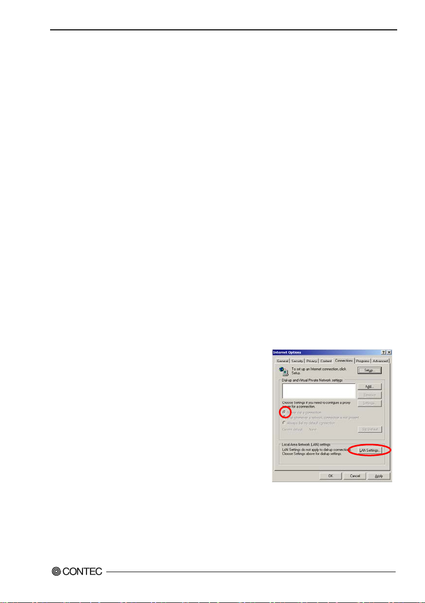
- Internet Explorer
(1) Launch Internet Explorer.
(2) From the [Tools] menu, selec t [Internet Options], and
then click the [Connections] tab.
(3) In the dial-up settings area, selec t "Never dial a
connection".
* If the option is grayed-out, go to the next step.
(4) Click [LAN Settings].
or higher
FXA2000-G
21
Page 29
3. Connecti on to Devices and Setup Methods
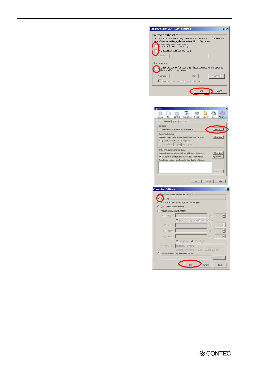
(5) C l ea r the "Au tomaticall y d etect set ting s ", "Use
automat ic configurati on script", and "Use a pr oxy
server for your LAN" check boxes, and then click
"OK".
(6) Click "OK", and then e nable the setti ngs.
- Firefox3.0
(1) La u nc h F irefox.
(2) From the menu bar, click [Tools] - [Options].
(3) Click [Advanced], open the [Network] tab, and then
click [Settings].
(4) Select "No prox y", and then click "OK".
(5) Click "OK" button.
FXA2000-G
22
Page 30
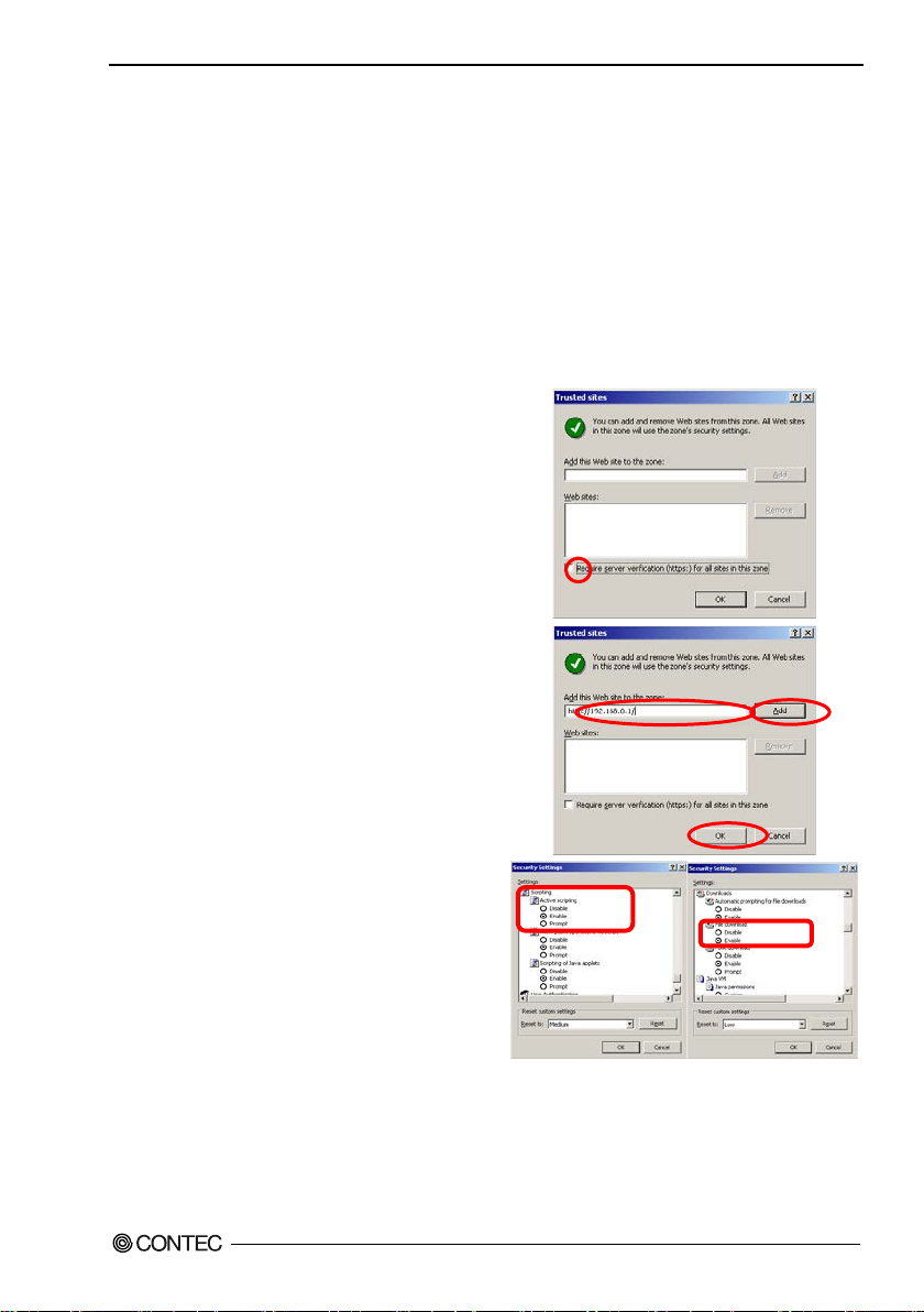
(2) Enable JavaScript.
In the "Add this website to the zone" box, type
The foll owing example settings are for Internet Explorer and Firefox .
Actual settings will depend upon t he environment you are using. For details, see your web browser's
help inf ormation or contact the softw a re manuf ac turer.
- Inter n et E x plorer
(1) Click [Start] - [Control Panel] - [Network and Internet] - [Internet Options].
* If using Wi ndows Vista or Windows XP, click [Start] - [Control Panel] - [Classic View] (or
[Swi tch to C l assic Vie w] ) - [Inte rnet Options].
(2) Click the [Security] t ab, and then click [Trust ed sites] - [Sites].
(3) Clear the "Require server verification (https:)
for all sites in thi s z on e" check bo x.
(4)
"http://192.168.0.1/", click [Add], and then
click [Close]. * If using Internet Explorer 6.0,
in the "A dd t hi s w e b site
to the zone" box, type", http://192.168.0.1/",
click [Add], an d then click [OK].
* If you have chan ge d t h is produ ct's IP addr e s s,
type the set IP address.
(5) Click [Custom Level].
(6) Scroll do w n a nd s el ec t "Enable" under "Active
scripting" and "File download", and then click
[OK].
(7) Click [Yes], click [Apply], and then click [OK]
to enabl e t he se ttings.
3. Connecti on to Devices and Setup Methods
FXA2000-G
23
Page 31
3. Connecti on to Devices and Setup Methods
CAUTION
CAUTION
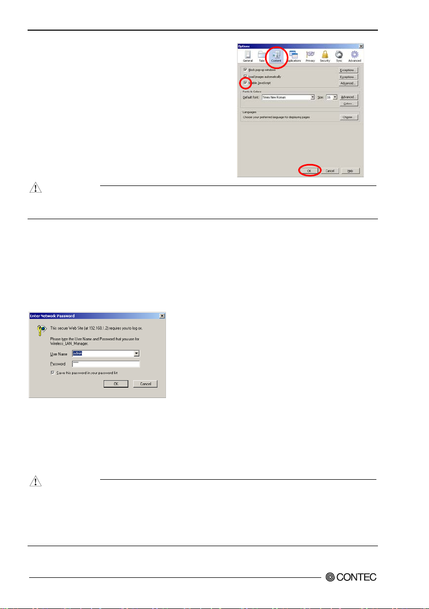
- Firefox3.0
(1) L a u nc h Fi refox.
(2) From the menu bar, click [Tools] - [Options].
(3) Click [ C ontent] , an d t h e n s el ect the "Ena ble
JavaScript" check box.
(4) Click "OK" button.
When the Web browser setti ngs have been changed, rest ore the original browser settings upon the
compl et i o n o f s etup of this pr o du ct.
Connecting to This Product Using Web Browser
The foll owing lo gin screen is displa y e d w h en connect e d to t hi s pr o du ct using web browser.
If the login scre e n is n ot displa ye d, the IP address setting for PC, brows er setting s, or the URL en te r e d i n
the address bar of the browser may be incorrect.
When connecting for the first time, enter the default user name (admin) and password (pass) and click
[OK].
Figure 3.1. Login screen
There will be no p roblem if you just save the settings now but reb oot the product later when necessary. In
this case, sa ving the settings does not actually change the settings of the product. Therefore, make sure
to reboot the product later.
* For explanations of functions and setting instruct ions, see the manual available from the CONTEC
webs ite or se e h elp inf ormation.
It takes approximately 5 - 10 seconds to save settings (writing to inter nal flash memory). During tha t
period, the LEDs fo r POWER, LAN an d WLAN at the front part of the m ain unit blink
simultaneou sly. Do not re boot or tur n off the product until the screen indicates the completion of the
saving process. The setup file data and firmware data may be damaged and the product may not
operate properly if it is rebooted or switched off during the saving process.
FXA2000-G
24
Page 32
4. Setup and Status Display
4. Setup and St atus Display
This chapter describes how to setup the AP using a web brows er, explains each set ting item and sta tus
display and IEEE802.1X supplicant setting. Always read Chapter 2 “Setup” and Chapter 3 “Connection
to Devices and Setup Methods” for preparation before performing setup or vi e wing the stat us.
This section describes how to perform setup using a web browser.
Basic settings
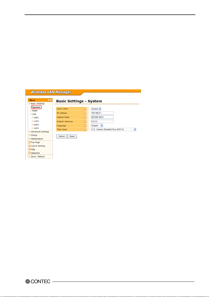
System
DHCP Client
To set the IP addre ss of the de v ice using th e DHCP client function, set to "Enable". To speci fy the IP
address of the device, set to "Disable".
When set to "Disable", the address c onfigured by "IP Address" is the IP address fo r the device.
Default setting : Disable
IP Addr e s s
Set the IP address for the device. This setting is valid when "DHCP Client" is set to "Disable".
Default setting : 192.168.0.1
Subnet Mask
Set the subnet mask for the device. This set ting is val id when "DHCP Clie nt" is set to "Disable".
Default setting : 255.255.255.0
Default Gateway
Set the IP address of the default gateway for the device. This setting is valid when "DHC P Client" is set
to "Disable". T o di sable thi s se tting, enter "0.0. 0 .0 " .
Default setting : 0.0.0.0
FXA2000-G
25
Page 33
4. Setup and Status Display
Item
Description
The device serves as a base station for client devices to connect to under the access point.
The device serves as a client device (slave station) to connect to a station access point.
VAP1 settings are the access point settings. VAP2 settings are the station settings.
On networks that use two or more repeaters, configure the
also recommend that you set "Wireless Connection Mode" to "Advanced Infrastructure".
Language
Set the lang uage to display the "Wireless LAN Manager" configuration web page.
You can select either "Japanese" or "English".
Default setting : Japanese
Time Zone
Set the time zone for the device .
Default Settin g : EST+5
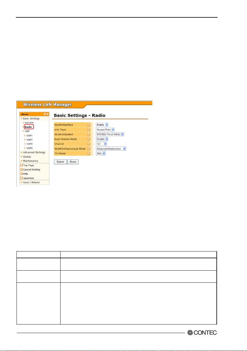
Radio
WLAN Interface
To use the wireless interface, set to "Enable". If set to "Disable", wireless networking cannot be used, so
this se tting shou l d normally be "Enable".
Default setting : Enable
Connec tion to Dev ices and Setup Methods Select the operat ion mode as "Access Point", "Station", or
"Repeater".
Default setting : Access Point
Table 4.1 Description of Unit Type
Access Point
Station
Repeater
FXA2000-G
26
Virtual AP settings can be configured for VAP1 to VAP4.
Only VAP1 settings are used.
The device operates simultaneously as a repeater access point and a station and it serves as a
repeater.
On wireless networks that use repeaters, the channel and wireless networking spe cification
must be the same for all devices.
"Preferred AP" and "Connections to Non-Preferred APs " functions in the advanced settings
and take care to specify the connection destination clearly so the repeaters do not loop. We
Page 34

4. Setup and Status Display
Repe ater Independent
When "Disable" repeater in dependent, behavior of the repeater access point (VAP1) and the repeater
station (VAP 2) are linked. Repeater stat ion (VAP 2) is not connecte d to an access point, repeater access
point (VAP1) will not work. In add it ion, the channel conf iguration is ignored, and operate on the same
channel as the access point to which the repe ater station (VAP2) is connected.
When "Enable" rep eater independent, the repeater access point (VAP 1) and the rep eater stat ion (VAP2)
operate independently and separately. Regardless of whe ther the repeater stations (VAP2) are connected
to the access point, the rep eater access point (VAP1) operates. The repeater station (VAP2) can only be
connected to the access point same cha nnel setting.
Default Settin g : Enable
WLAN Standard
Selec t the wire less networking standa rd to use on the devic e .
When the unit type is "Stat ion", the "Auto" select ion appears. Auto means both "IEEE802.11n(5GHz)"
and "IEE E802.11n(2.4GHz)". If you wan t t o a llow connections to both the 5GHz and 2.4GHz wire less
networks, select "Auto". When set to "Auto", dual channel mode is fixed a s "E nable".
Default Settin g : IEEE802.11n ( 2.4GHz)
Dual Channel Mode
This setting can only be configured when the wir eless networking standard is "IEEE802.11n(5GHz)" or
"IEEE802.11n(2.4GHz)". To set the wireless networking bandwidth to 20 MHz, select "Disable". To s et
it to 40 MHz, select "En able". However, even when set to "Enable", if the connected wireless device
has dual channel mode set to "Disable", the bandwidth is 20 M Hz. When set to "Enable", communication
is performed with a bandwidth of 40 MHz when possible.
Default setting : Disable
Channel
This setting is available when the unit type is "Access Point" or "Repeater". Select the channel to use on
the device. The channel that can be used changes acco r ding to the select ed wireless network ing standard
and unit type.
Default setting : 1
WLAN Inf rastr ucture Mode
Select the operati on mode for the device. There are three types of operat ion modes: "Standar d
Infrastructure", "Compatible Infrastructure", and "Advanced Infrastructure". When the unit type is
station, "Advanced Infrastructure" cannot be selected.
Default setting : Advanced Infrastructure
FXA2000-G
27
Page 35
4. Setup and Status Display
Item
Description
A configuration where a standard infrastructure access point is the core and stations (wireless
A configuration where a compatible infrastructure access point is the core and stations
A mixed mode of both modes where the device can use an advanced infrastructure access point
as standard infrastructure while also using compatible infrastructure at the same time.
Table 4.2 Description of Wireless Connection Mode
Standard Infrastructure
Compatible
Infrastructure
Advanced Infrastructure
networking cards, etc.) are locate d under it. (Infrastructure)
With standard infrastructure, the device can use its own wireless networking feature.
(wireless networking cards, etc.) are located under it. (Infrastructure)
Select this mode when connecting to access points created by other companies. However, the
device cannot use its own wireless networking feature.
TX Power
Select the transmit power.
You can select either "MAX, "50%", "25%", or "12%".
Default setting : MAX
Antenna
This setting can only be configured when the wir eless networking standard is "IEEE802.11a",
"IEEE802.11b", or "IEEE802.11g". Select the antenna mode as "Auto" or "Fixed (Antenna:1)". This
setting is not normally required. When using the device with only one external ante nna installed, select
the antenna mode as "Fixed (Antenna:1)". Sele ct t h e t r a nsmit p o w er.
Default setting : Auto
VAP
FXA2000-G
28
Page 36
4. Setup and Status Display
CAUTION
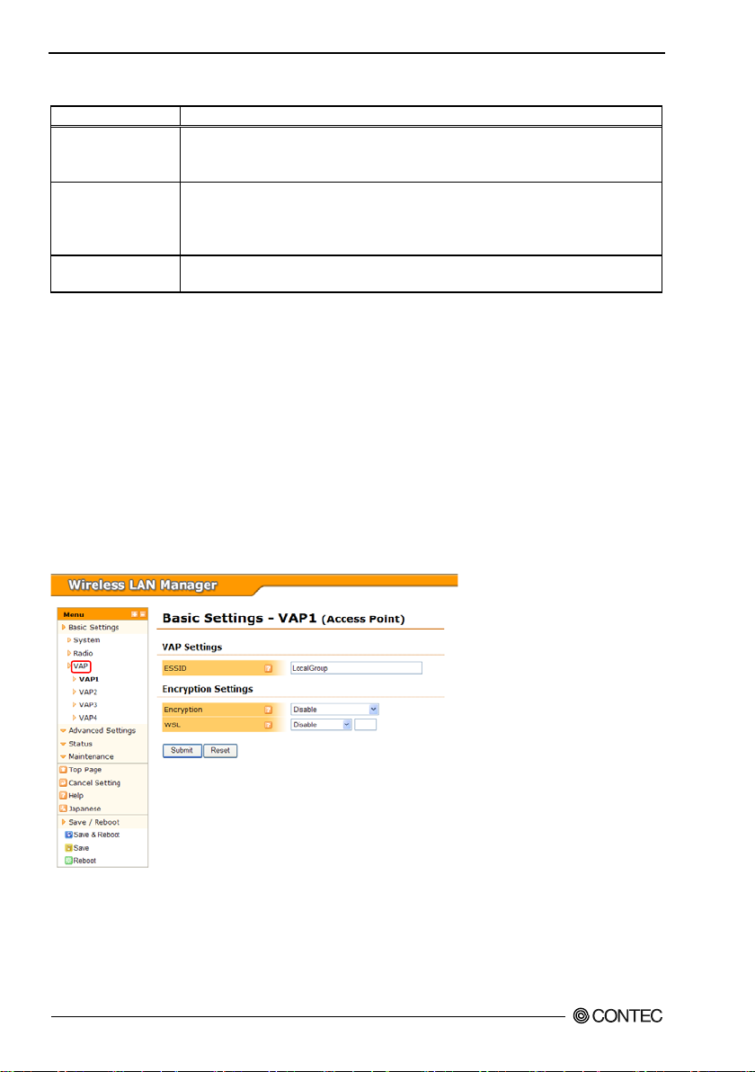
▼VAP Settings
ESSID
Set the ESSID for the device as alphanumeric char acters between 2 and 32 characters in length. The
ESSID for VAP1 must be set.
When the unit type is "Access Poin t", VAP2 through VAP4 (vir tual AP) are enabled by configuring their
ESSIDs. When sett in g the ES SID s for multiple VAPs, ensure that the ESSID values are not already in
use.
When the unit type is "Station" , the VAP2 through VAP 4 settings are not required.
When the unit type is "Repeater", set the ESS ID for VAP 1 a nd VAP2. Due to the ch aracteristics of the
repeater, normally set the ESSID for VAP1 and VAP2 to the same setting.
Default setting : LocalGroup
▼Encryption S ett in gs
Encryption
Select the encryption to use with wireless networking. Fur ther settings that must be configured are
displayed depending on the selected setting, so c on f igu re the di spl ayed set tings.
Default setting : Disable
WEP and TKIP cannot be used with IEEE 802.11n due to the rules of the standard. Note that when
the wi rel ess networking standard is IE EE 802.11n and encryption is configured that uses those
settings, the device will operate with the legacy standards (IEEE 802.11a and I EEE 802.11g) .
WSL
The sett i n g tha t selec t s w he ther or not to en crypt wir e le s s data with ou r proprietary encryption ( WSL).
Note that communication between a terminal with the WSL feature enabled and a terminal with the WSL
feature disabled is no t possible. This device can only use WSL (Type 2) that utilizes the new a lgorithm.
The WSL key setting is only valid when the WSL feature is enabled. Note that communication between
terminals with different WS L k eys is not possible.
Enter the WSL key as a 20 digit hexadecimal value (0 to 9, a to f or A to F).
Default setting : Disable, (Blank)
▼Key Setting
Default Key
This se tting is only availa bl e when the e nc r y pt ion is set t o ei t h er "WEP(O p e n) " , "WEP(SharedKey)",
"WEP(Aut o)", or "AE S".
Selec t the key to use as "Fixed Key 1" to "Fixed Key 4".
Default setting : Fixed Key 1
FXA2000-G
29
Page 37

4. Setup and Status Display
Fixed Key
This setting is o nly availa ble when t h e e nc r y ption is set to either "W EP(Ope n)", "WEP(Share d Ke y)",
"WEP(Aut o)", or "AE S".
Set the fixed key . Set as a hexadecimal value (0 to 9, A to F).
For "WEP", there are three lengths of fixed keys: 64 bits, 128 bits, and 152 bits. Thes e ke ys require you
to enter 10 characters, 26 char acters, and 32 characters.
For "AES", the length is only 128 bits, so en ter 32 characte rs.
The fixed keys are a common setting for the VAPs. The fixed keys are displayed in the sett ings for ea ch
VAP, but if the setting is changed, the change is reflected in the fixed keys for the other VAPs.
Default setting : (Blank)
▼RADIUS Server Settings
Recertification Interval (sec)
When the encr yption is set to "IEEE802.1X", "WPA", or "WP A2", set t he interval for reauthentication in
seconds. This setting can be configur e d as 0 (disabled) or betwe en 120 (2 minutes) and 259200 (3
days).
When set to 0, the set ting is disabled and reauthentication is not performe d.
Default setting : 0 (disabled)
Server IP Address
When the encryption is set to "IEEE802.1X", "WPA", or "WPA2", set the IP address for the RADIUS
server.
Default setting : 0.0.0.0
Serv er Port
When the encr yption is set to "IEEE802.1X", "WPA", or "WP A2", set t he port number for the RADIUS
server.
Default setting : 1812
Shared Secre t
When the encr yption is set to "IEEE802.1X", "WPA", or "WP A2", set t he shared secret for the R ADIUS
server as alphanumeric characters with a maximum length of 64 characters.
Default setting : (Blank)
▼Authentication Supplicant Settings
Authentication Type
Set the RADIUS authentication type to either "PEAP" o r "EAP-TLS".
When "PEAP", y o u must reg ister a s erver ce rt ificate wit h "Certi f icate R eg istra t i o n".
Whe n " EAP-TLS", you must register the server certificate, client certificate, and private key with
"Certificate Registration".
Default setting : PEAP
FXA2000-G
30
Page 38

4. Setup and Status Display
User Name
Set the authen tication user name f or RADIUS authen tication as alph anumeric characters with a maxim um
length of 32 char acters.
Default setting : (Blank)
User Password
Set the authentication password for RADIUS authentication as alphanumeric characters with a maximum
length of 32 char acters.
Default setting : (Blank)
Certificate Re gistration
Register (upload) the certificates required for RADIUS authentication.
When you click the button to regis ter certificates, the ce rtificate re gistration frame w ill open. Brow se to a
fil e in that frame and upload the certif icate to the device with the "Register" button.
Next to the button to open the certificate registration frame is a message tha t indicates whether or not that
certificate has been reg ist ered. When the certificate is register ed, "Registered" is displayed. When not
registered, "N o t Re gistere d" is displa y e d.
This message is reflected by clicking the "Confirm" button or by reloading the page after the certificates
are registered (uploaded).
Default setting : (Not Registered)
Convert ing certificate files from PKCS12 format by OpenSSL
PKCS#12 forma t cli ent c ertif i cate : u ser1.p1 2
Password of client certificate: user1
DER format client certificate: user1.der
DER format private key: user1-pkey.der
1. openssl p kcs12 -nocerts -nodes -in user1.p12 -out user1-pkey.pem -passin pass:user1
2. openssl rsa -in user1-pkey.pem -inf o rm PEM -out user1-pkey.der -outform DER
3. openssl p kcs12 -clcerts -in user1.p12 -out user1. pe m -passin pass:user1 -pass out pass:user1
4. openssl x 509 -in us er 1.pem -i nform PEM -out user1.der -outfor m D ER
▼WPA Setting s
Group Key Updating Interval (sec)
When the encryption is set to "WPA", "WPA2" , "W PA -PSK", or "WPA2-PSK", set the group key
updating interval in seconds.
This set ting can be configured as 0 (disabled) o r between 120 ( 2 m inutes) and 259200 (3 days).
When set to 0, the setting is disabled and group key renewal is not performed.
Default setting : 3600
▼PSK Setting s
WPA Pre-Shared Key (PSK)
When the encryption is set to "WPA-PSK" or "WPA2-PSK", se t the WPA encryption key (PSK:
pre-shared key) to use for en cryption .
Enter the value as alphanumeric characters between 8 and 63 characters.
Default setting : (Blank)
FXA2000-G
31
Page 39
4. Setup and Status Display
Advanced Settings
System
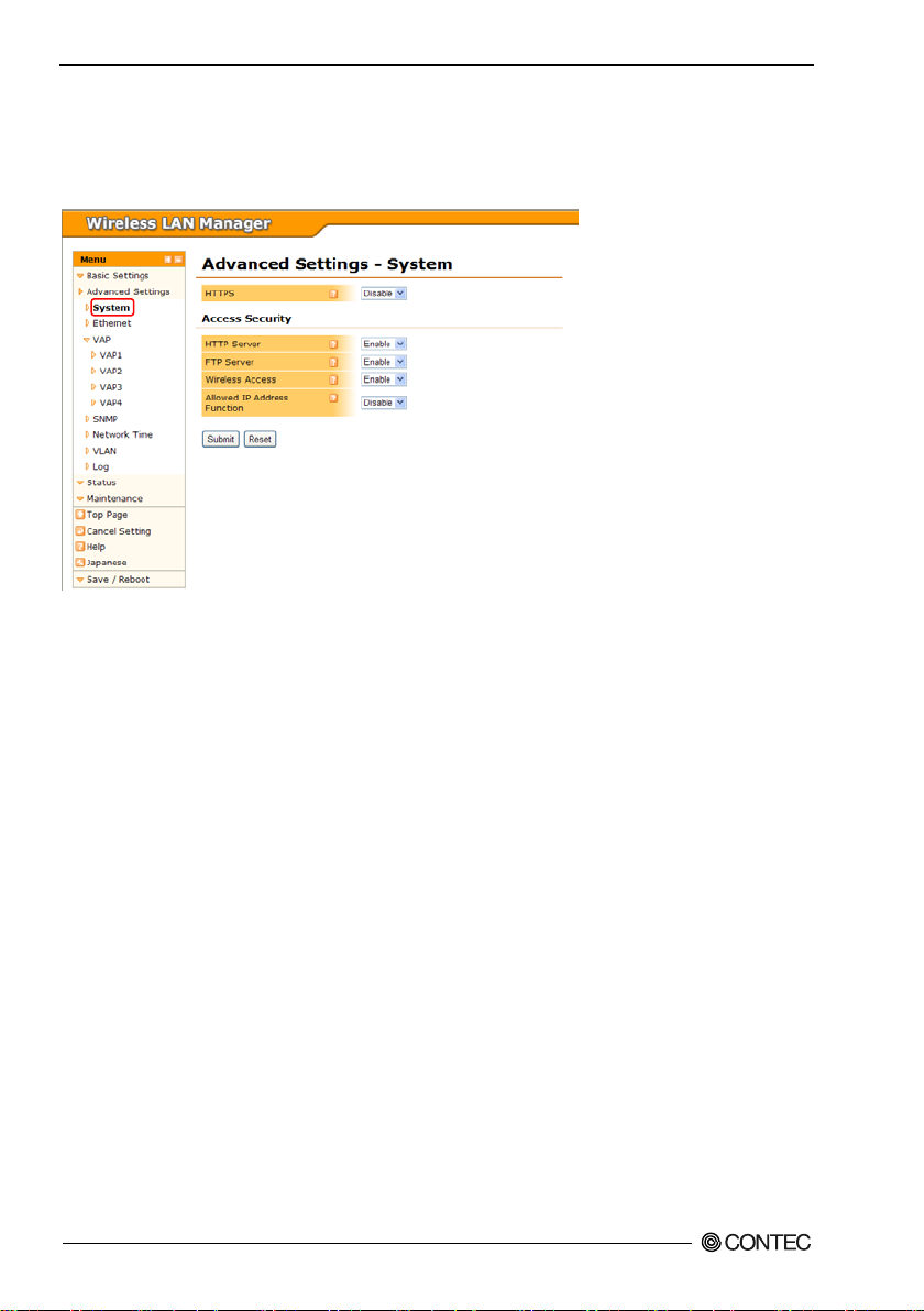
HTTPS
To use the H TTP S function (Port 443), set to "En able".
By accessing the https://(IP address), HTTP over SSL/TSL c o m mu nication is enabled.
Default setting : Disable
▼Access Security
HTTP Server
To use the H TTP Server (Port 80), set to "Enable".
Default setting : Enable
FTP Server
To use the FTP Server, set to "Enable".
Default setting : Enable
Wireless Access
By setti n g to disabl e th is featur e , you can den y a c ce s s t o HTTP and FTP via wireless LAN, and allow
acce s s o nly via ethern et.
Default setting : Enable
Allowed IP Address Function
If you want to use the functi on to spec if y the IP addresses that can access the HTTP or FTP, set to
"Enable".
Default setting : Disable
FXA2000-G
32
Page 40
4. Setup and Status Display
CAUTION
Allowed IP Address
When the "Enable" allowed IP address function, specify the IP addresses t hat are allowed to access. You
can specify the IP a ddress to specify a range, or only one.
If you specify only one, enter the IP address only in the left form of the allowed IP address 1/2. If you
specify a range, enter the start IP add ress in the left fo rm of the allowed IP address 1/2, and enter the end
IP addr e s s in th e right form.
Please note that because if you've set the IP address that is not intended, you may become no t be abl e t o
access th is equipment in a FTP or HTTP. If yo u've lost the IP address, you will nee d to be initialized with
the initialization switch.
Default setting : Blank
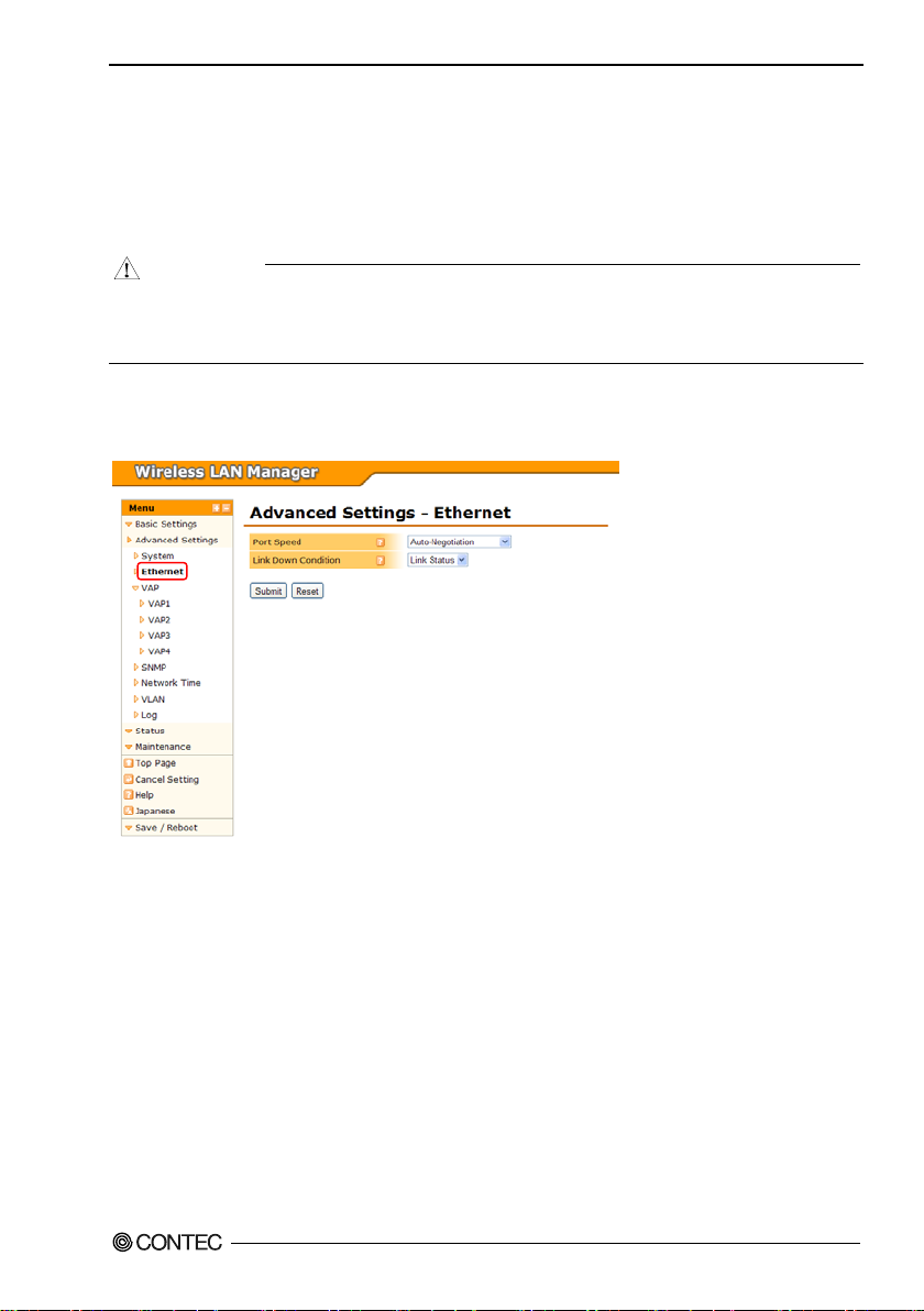
Ethernet
Port Speed
Select the Ethernet port speed. You ca n s elect from "Auto-Nego tiation", "100Mbps(full duplex)",
"100Mbps(half duplex)", "10Mbps(full duplex)", and "10Mbps(half duplex)".
"Auto-Negotiation" is used normally.
Default setting : Auto-Negotiation
FXA2000-G
33
Page 41

4. Setup and Status Display
CAUTION
- If one side is set to "Auto" an d the other side is se t to "100M Full Duplex", th e com munication mode
for the "Auto" side is recognized as "100M half Duplex". In this case, the re may be a high error rate
and norma l commun ication may not be possible. It is recommended that you se t th e correct
communica t ion mode.
- If one side or both sides are set to "Auto" a nd the two sides cannot recognize each other, set the
communication mode to the unchanging setting for both sides.
- If port speeds are set incorrect ly (for exa mple, one side is set to unc hanging 10M and th e other side is
set to un changing 100M), only one de vice may be abl e to e sta b l i sh a li nk or the link ma y be
repeatedly esta blished and disconnected depending on the communi cation status. In this case, set the
correct communication mode.
Link Down Condition
When "Link Down S e n se " is enabled in t h e " Ad vanced Se t tings" for each VA P, s et the link down
judgm e nt c on dition.
The con dition for "L ink Statu s " i s when the Eth ernet link is discon ne c t e d. The con dit i on for "Pin g" is
when a specific address c an no longer be pinged, in addition to that for "Link Status".
When "Ping" is selected, the settings for "Ping Parameters" appear.
Default setting : Link Status
Ping IP Address
When the link down condition is set to "Ping", set the IP address for the device to ping.
Set the IP address for the device to ping to a device connected to this device by the wired network.
Be careful not to set the IP address for a d evice that cannot be pinged when thi s device starts, such as
setting the IP address to a device on the wireless network.
Default setting : 0.0.0.0
Ping Int erval (sec)
When the li nk down condition is set to "Ping", set the inte rv a l t o ping the IP address between 1 and 65535
seconds.
Default setting : 60
Ping Response Wait Time (sec)
When the li nk down condition is set to "Pi ng", set the interval to ping the IP address between 1 and 65535
seconds. Set this v a lue betwee n 1 and 15 seconds.
Default setting : 3
Ping Retry Count
Set the number of times to retry pinging the IP address from 0 to 15.
When a ping timeout oc curs, the ping is retr ied withi n the number of times set here. If all the pings
timeout, the ping is judged to have failed.
Default setting : 3
FXA2000-G
34
Page 42
4. Setup and Status Display
VAP
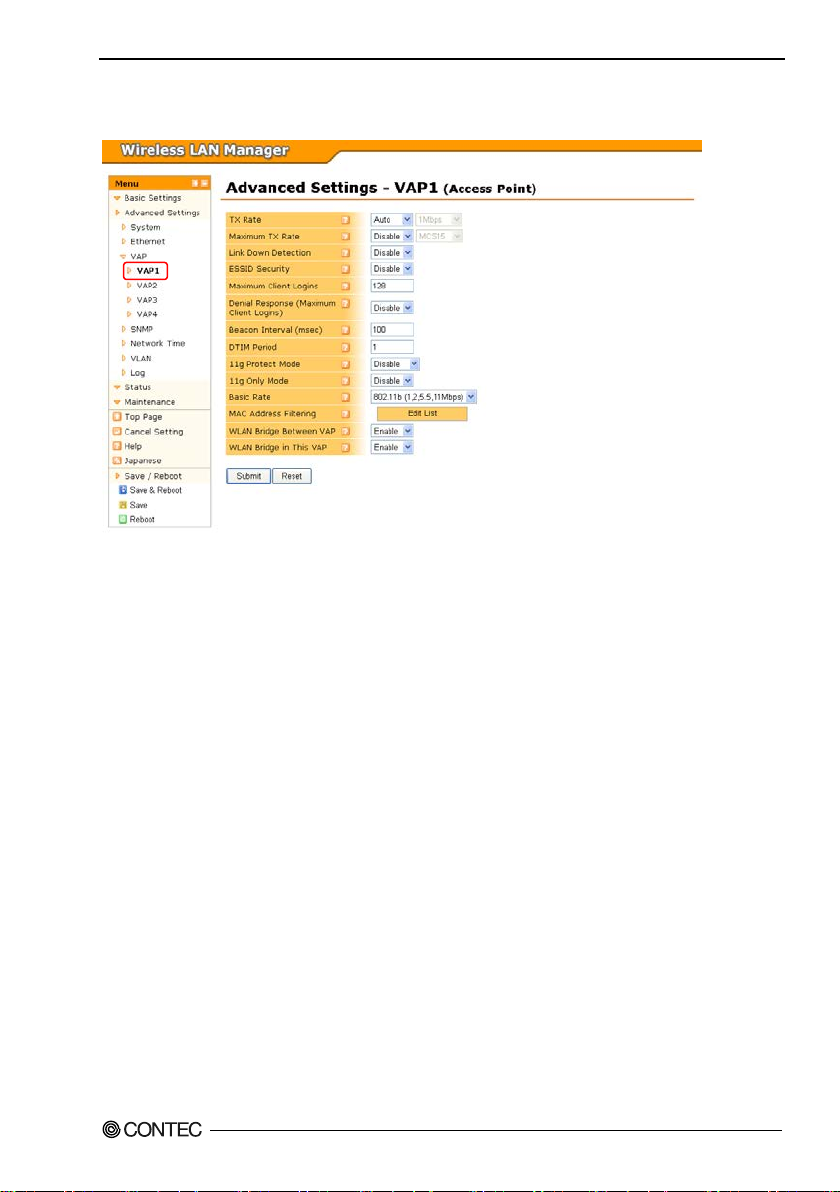
TX Rate
Set the TX rate for wireless networking for the device.
This setting is nor mall y set to "Aut o ". To fix the TX rate, select "Manual" and select the fixed TX rat e.
Default Settin g : Auto, 1Mbps
Maximum TX Rate
When the TX rate is "Auto", set the upper limit for the TX rate.
This setting is nor mall y set to "Disable". To fix the ma x imum TX rate, select "Enable" and specify the
rate. The device can automat ically select and communicate at a rate that does not exceed the specified
rate.
Some rates cannot be set as the maximum TX rate due to the wireless LAN standard. Those rates are not
shown in the drop-down list.
Default setting : Disable, MCS15
Link Down Detection
This function monitors the wired net working port and stops the wireless function when the wired
netwo rking port li nk is down (wh e n disconnected). To use thi s function , s et to "Enable ".
If the unit type is set to "Station", use caution when using this function because the wireless network
cannot be accessed when the wired networking port is down.
This setting is not available when the unit type is set to "Repeater". It is forcibly set to disabled.
Default setting : Disable
FXA2000-G
35
Page 43

4. Setup and Status Display
ESSID Security
This setting is available when the unit type is "Access Point" or "Repeater".
You can prohibit a c ce s s by ANYID ter minals (termina ls with no ESSI D s et) by setting ESSID s e curity to
"Enable", and you can also hide the ESSID fro m being broa d ca s t by the station.
In this manner, you can restrict unauthorized access using ANYID and prevent third parties from easily
learning the ESSID.
Default setting : Disable
Maximum Client Logins
This setting is available when the unit type i s " A ccess P oi n t " or " Repeater".
Set the number of client logins to the station. The value can be set from 1 to 128 for each VAP.
Howeve r, note that the total number of logins fo r al l VAPs (VAP1 to VAP4) is 128. When the total
number of client logins is 128, even if the number of logins to the VAP set here does not exc e ed the
maximum number of logins, stations can no longer log in.
Default setting : 128
Denial Response (Maximum Clien t Logins )
When the login number has reached to "Maxim um Client Lo gins", is to ignore the connection request
from the s tation, does not return a response. To use this function, set to "Enable".
This feature, you might want to use when there is the station to connect repeatedly.
Default Settin g : Disabled
Beacon Interval (msec)
This setting is available when the unit type is "Access Point" or "Repeater".
Set the interval to send the beacon.
This value can be set between 100 ms and 1000 ms. It is not norm ally necessary to change the default
value (100 ms). Thi s s etting is a c om m o n s etting for the VAPs.
Default setting : 100
DTIM Interval
This setting is available when the unit type is "Access Point" or "Repeater".
Set the DTIM (delivery traffic indication message) interval which is information added to the beacon for
wireless terminals in a power-saving stat e to cancel that state.
This va lue can be set as 1 to 15.
Default setting : 1
11g Protect Mode
When the w ireless networking standard is IEEE 802. 11n (2.4 GHz) or IEEE 802.11g, protect mode is
used for stable communication in an environment wit h a m ix of IEEE 802. 11b wireless terminals by
setting "RTS -CTS" or "CTS only".
When "RTS-CTS", RTS and CTS are used. When "C TS only", only CTS is used.
11g protect mod e is di s pl a y e d f or each VAP, but this se tt i ng is commo n t o V A P1 t hrough VAP4.
Default setting : Disable
FXA2000-G
36
Page 44

4. Setup and Status Display
Ping Parameters
This setting is available when the unit type is "Access Point" or "Repeater".
When the w ireless networking standard is IEEE 802. 11n (2.4 GHz) or IEEE 802.11g, this function
prohibits logins by IEEE 802.11b wireless terminals. To use this function, set to " Enable".
Default setting : Disable
Basic Rates
When the unit type is access poin t or repeater and the wireless networking standa rd is IEEE 802.11b,
IEEE 802.11g, or IEEE 802.11n (2.4 GHz), you can se t the basic rates.
You can select "802.11 (1, 2Mbps)" or "802.11b (1, 2, 5.5, 11Mbps)".
If 11g onl y m ode is enab l e d, t his settin g i s ignored.
Default setting : 802.11b (1, 2, 5.5, 11 Mbps)
MAC Address Filtering
This setting is available when the unit type is "Access Point" or "Repeater".
The d ev i c e can all o w l o gins from stat ions (cl ient termina ls) wit h t h ei r wireless M AC addr es s e s re gister ed
in adva n ce an d f orbid logins fro m all ot h er s t a tions by ena bling th e M AC addre ss filteri ng fu n ction.
To enable the function and to edit the list of terminals allowed to log in, click the "Edit List" bu tton and
use the page that is displayed.
Enter the addresses to register in "Registered Add resses". Enter the MAC address as two characters, a
hyphen, two characters, and so on. (Ex: 00-80-4C-00-00-00)
To register only a single address, enter the address only in "Regis tered Address (Start)" and click the
"Add" button. To set a range of a ddresses, enter the range in "Registered Address (Start) " and "Registered
Address (End), and click the "Add" button. All the MAC addresses within that range ar e allowed.
The registered addresses are applied only to the VAP checked with "VAP". Typically there is no problem
leaving VAP1 through VAP4 checked. W hen applicable VAP s are specified, select the VAPs to check.
The registere d MAC addre s s e s ar e display e d in th e "M AC A d dress Filt er i ng List". W he n you wish t o
delete an entry, cli ck the "DEL" button for the appr opriate entry to delete it. Click the "ALL" button to
delete all the entries.
A maxi mum of 1024 MAC addresses that allow login can be registered.
Default setting : Function: Disable, no entries
WLAN Bridge Between VAP
This setting is available when the unit type is "Access Point".
When s et to "Disable", nod e o n this VAP ca n no t co m municate (WLAN bridge) with node s o n oth er
VAPs. When set to "Enable" this is allowed.
Default setting : Enable
WLAN Bridge in This VAP
This setting is available when the unit type is "Access Point".
When s et to "Disable", nod e o n this VAP ca n no t co m municate (WLAN bridge) with other nodes on t hi s
VAP. When set to "Enable" this is allowed.
Default setting : Enable
FXA2000-G
37
Page 45

4. Setup and Status Display
Multi-Client
This set ting is ava ilable when the unit type is "Station" or "Repeater" and the wireless connection mode is
"Compatible Infrastructure".
To connect multiple PCs under this dev ice, set to "Enable".
When set to "Disable", only one PC can connect under this device.
When the unit type is "Repeater", this setting is not available in VAP2. It is forcibly set to enabled.
Default setting : Disable
Static No de Ad dress
This setting is available when the unit type is "Station" or "Repeater", the wireless connection mode is
"Compa tible Infrastructure", and t he multi-client function is "Disable".
Enter the MAC address for the PC that will connect to this device. Normally this setting is required when
connecting to a device that will only receive communications, such as a POS terminal.
When not using this function, enter the MAC a ddress "00-00-00-00-00-00" which i ndicates it is disabled.
This se tting is not normally re quire d, so it is set to "00 -00-00-00-00-00".
Enter the MAC address as two characters, a hyphen, two characters, and so on. (Ex: 00-80-4C-00-00-00)
When the unit type is "Repeater", this setting is not available in VAP2. It is forcibly set to disabled.
Default setting : 00-00-00-00-00-00
Roaming Threshold
This setting is available when the unit type is "Station".
When the RSSI value for the connected access point falls below the set value, the station scans access
points and se arc hes for an access poi nt that it can roam to.
This va lue can be set as 0 to 106. The larger the value, scans happen more often (roam ing happens more
easily). The smaller the value, scans happen less often (roaming happens less easily).
When the unit type is "Repeater", this setting is no t ava ilable i n V AP2 .
Default setting : 24
Scan Channels
This setting is available when the unit type is "Station".
Sele ct the channels t o be scan n ed.
Note t hat communication between access point that is not set to the channel to be scanned is not possible.
Default setting : (All)
FXA2000-G
38
Page 46

4. Setup and Status Display
Preferred AP
This setting is available when the unit type is "Sta tio n" or "R epeater".
This setting is for when there are multiple access points that can be connected to and you wish to apply a
priority to the access points.
You can s et t he ac c e s s p oin t to prefer en ti a lly conn e ct t o b y s pe c ifying thi s s etting. E nter the wir e le s s
MAC addr ess for the access points in "Preferr ed AP1" to "Preferred AP5".
For the priority of access points to connect to, "Preferred AP1" has the high e st priority, "Pre fer red AP5"
has the lowest priority. This function is enabled by entering a valid wireless MAC address. When entering
MAC addresse s, sp e ci f y them in ord er fr o m "Preferred AP1".
When not using this function, enter the MAC a ddress "00-00-00-00-00-00".
Enter the MAC address as two characters, a hyphen, two characters, and so on. (Ex: 00-80-4C-00-00-00)
When the unit type is "Repeater", we recommend that you configure this setting and clearly specif y the
connection destination in the settings for VAP2 (station) on networks with two or more repeaters. If you
do not specify the connection destination, when a chain ed repeater goes down, repeaters under it may
connect to repeaters even further below themselves and form a loop.
By cli ck ing th e button to the right of the entry form, you can display a list of wireless MAC addresses for
access points based on the "Wireless Node Informa tion" in a drop-down list. By selecting an address from
this list, it ca n be entered in the form.
Default setting 00-00-00-00-00-00 (all 1 to 5)
Connec tions to Non-Preferred APs
This setting is available when the unit type is "Sta tio n" or "R epeater".
When using the pr eferred AP function and the device cannot connect to the access points specifi ed in
"Pref erred AP1" t o "P referred AP5", set whethe r or not to allow connections t o other access points.
To allow a connection to access points other than the access points specified as pr eferred APs, set this
settin g t o "Enabl e" . T o forbid connecti on s , set this setti n g t o "D i sable".
When the unit type is "Repeater", we recommend that you set this sett ing to "Disable" and clearly specify
the connection destination in the settings for VAP2 (station) on networks with two or more repeaters. If
you do no t s pe cify the co nnectio n d estination, when a chained repeater goes down, repeaters under it may
connect to repeaters even further below themselves and form a loop.
Default setting : Enable
FXA2000-G
39
Page 47
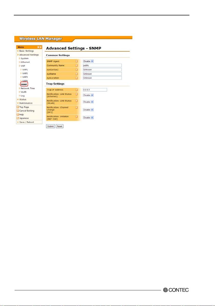
4. Setup and Status Display
SNMP
▼Common Settings
SNMP Ag en t
To enable the device's SNMP agent function, set to "Enable".
This device can be accessed by an external SNMP manager and its MIB can be acquired by enabling the
SNMP agent function.
Default setting : Disable
Commun it y N a me
Set th e S N MP auth e nt icati o n st r i n g , called the co m munit y name, a s alphanumeri c c haract ers wit h a
maximum length of 32 characters.
The SNM P au thentica tion str i ng works lik e a password for ac ce ss i n g the devi c e w he n u si ng SNMP. Th e
SNMP manager can access this device's MIB by using the community name.
Default setting : public
System Contact Address ( sy sContact)
Set the address for the system cont act as alph anumeric characters with a maximum length of 32
characters. It is oka y t o leave thi s value blank.
Default setting : Unknown
Syst e m N a me (sysName)
Set the SNMP name for the device as alphanumeric characters with a maximum length of 32 characters.
It is okay t o lea ve this va lu e bl ank.
Default Settin g : Unknown
FXA2000-G
40
Page 48

4. Setup and Status Display
Device Installation Location (sysLocation)
Set a description of the installation location for the device as alpha numeric characters with a maximum
length of 32 char acters.
It is okay t o lea ve this va lu e bl ank.
Default setting : Unknown
▼Trap Settings
Trap IP Address
Traps are a funct ion to notify user s that a change has occurred in the SNMP agent system. The trap
functi o n can be ena bl ed by speci f ying the trap destination IP address, and the trap is sent to the specified
IP address.
When set to 0.0.0.0, the trap function is disabled.
Default setting : 0.0.0.0
Notification : Link Status (Ethernet)
Set whe th er or not to s en d a tr a p wh e n t h e wi r e d n etwork link status has changed (link up/down).
When enabled, the device sends a trap regarding the wired network link status change.
Default setting : Disable
Notification : Link Status (WLAN)
Set whet her or not to send a trap when the wirele s s network link status h as changed ( link up/down).
When enabled, the device sends a trap regarding the wireless network link status cha nge.
Default setting : Disable
Notification : Channel Change (DFS)
Set whether or not to send a trap when a channel chang e occurs by DF S when "Unit Type" is access point
and "Channel" is set to a channel subject to DFS.
When enabled, t h e d ev i c e sends a trap re ga r d i n g t h e D FS channel change.
Default setting : Disable
Notification : Initialization (INIT-SW)
Set whether or not to send a trap when the devic e was initial iz e d by press in g the initiali zation switch on
the unit. When enabled, the device sends a trap regarding initialization by the initialization switch.
Default setting : Disable
FXA2000-G
41
Page 49
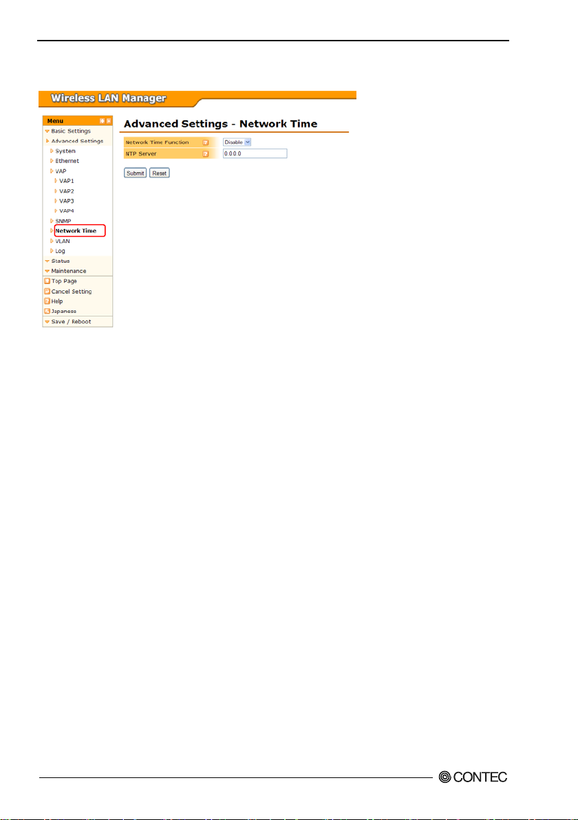
4. Setup and Status Display
Network Time
Networ k Time Function
The d ev i c e can sync hronize i t s time with n etwork tim e by enablin g t h e n etwork tim e functi on an d
configuring the NTP server setting. To use thi s function, select "E na ble".
Default setting : Disable
NTP Server
When enabling the network time function, specify the IP address for the NTP server.
Default setting : 0.0.0.0
FXA2000-G
42
Page 50
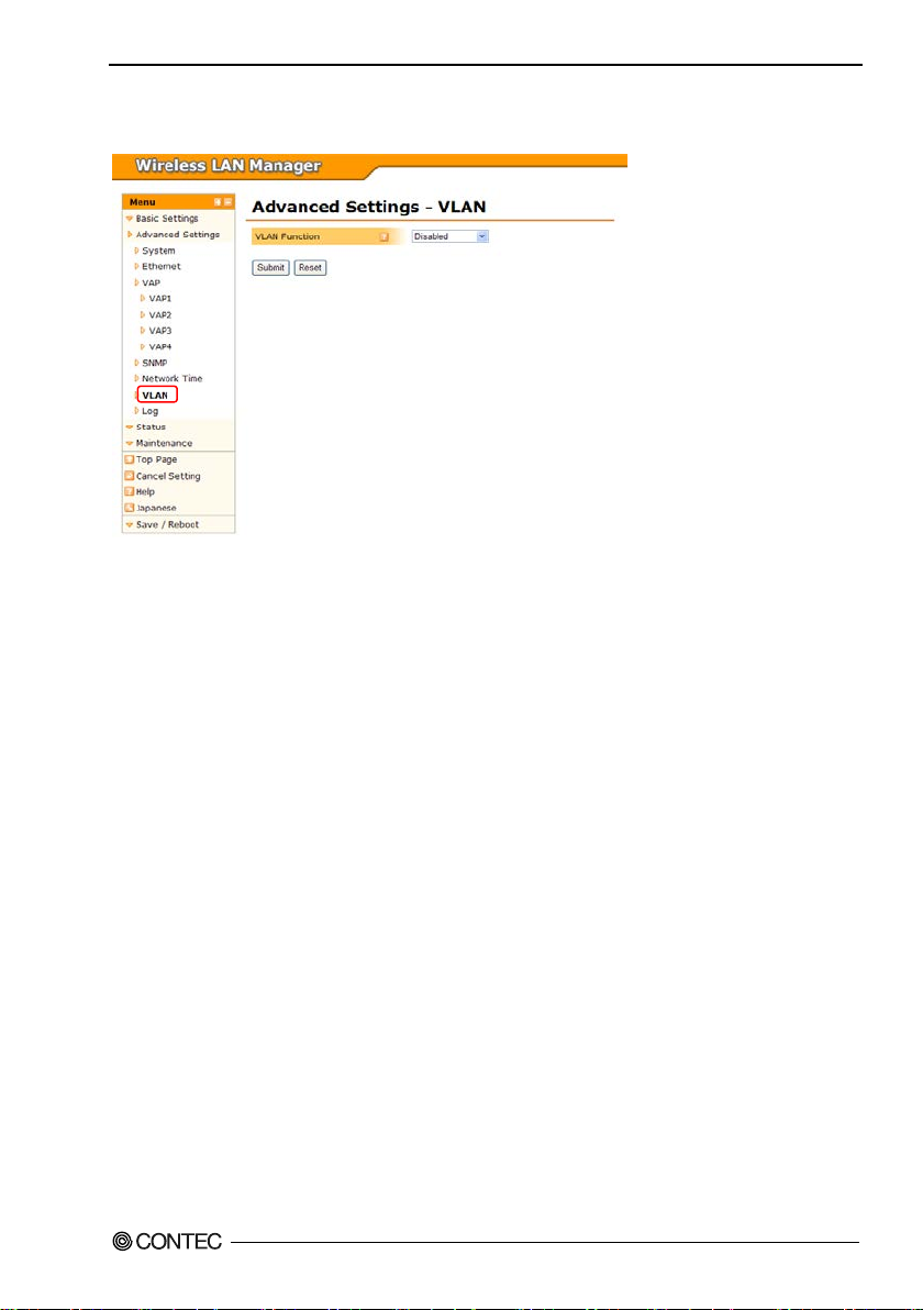
4. Setup and Status Display
VLAN
VLAN Function
To use the VLAN function, configure the settings. There are two types of VLAN: "Static VLAN" and
"Dynamic V LAN". To u s e t h e V LAN fun ction, se lect th e o n e t o u s e.
For "Static VLAN", set th e VLANID for each virtual AP ( V AP ).
"Dynamic VLAN " i s a VLAN funct i on that only passe s packets wit h an att ached VLANID ta g c on f igured
in the VLAN table.
When not using the VLAN function, set to "Disable".
Default setting : Disable
Local VLANID
Set the VLANID for the wired networking port on the device. Set this val ue betwe en 1 to 4094.
Default setting : 1
Native VLANID
Set the native VLANID. Set this value between 1 to 4094.
When you w ish to discard all packets without a VL AN t a g , s pe ci f y a n a ppropria t e VLANID that is
unused.
Default setting : 1
VAPVLANID
To use a static VLAN, set the VLANID assigned to the VAP (virtua l AP).
Specify this v a lue betwee n 1 to 4094. When the d evice is a re pea t er, only the VL AN ID for VA P1
(repeater AP) can be configu red. Wit h a repeater, VAP1 (repeater AP) and VAP2 (repeater ST) operate
with the sa me VLANID.
Default setting : 1
FXA2000-G
43
Page 51

4. Setup and Status Display
VLAN table - VLANID
To use a dynamic VLAND, you must create a VLAN table that specifies the VLANIDs to use. Set the
VLANIDs to use.
The V LANIDs can be set from 1 to 4094.
When using "Dynamic VLAN", at least one VLAN table en try must be create d.
Default setting : (Entirely blank)
VLAN table - VLAN name
Set the VLANID name. The VLA N n a m e can be en t ered up t o 32 character s, and it ca n also be s et to no
VLAN name (blank). However, when setti ng a VLAN name, take care not to u se a VLAN name for
anoth er entry.
Default setting : (Entirely blank)
FXA2000-G
44
Page 52
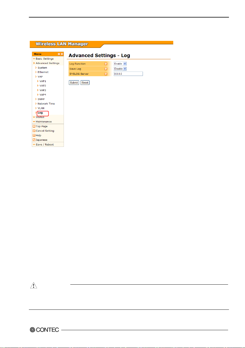
Log
C
AUTION
4. Setup and Status Display
Log Function
To record the log for the device using the log function, set to "Enable".
You can prevent the log from bei ng recorded by setting this setting to "Disable", but i n normal operation
this is unnecessary.
Default setting : Enable
Save Log
To save the recorded log information as a file, set to "Enable". To only temporarily retain the recorded
log information in me mory, set to "D isabl e" .
Temporary retention means the log information is retained only while the device is running. When
"Disable", th e log information is deleted when th e device restarts or the power is disconnected.
Default setting : Disable
SYSLOG Server
To send the acqui red log information to a SYSLOG serve r as a S YSLOG, set the IP address for the
SYSLOG server. When not sending the log inf ormation to a SYSLOG server, set to 0.0.0.0 to disable.
Default setting : 0.0.0.0
Debugging Log
Plea s e s e t t o "Enable " if you want to log f or more deta iled debugging.
You do not nee d to "Enable", usually.
Default setting : Disable
Please refer to help of browser setting screen for the explanat ion of a setting ite m etc. that increase
because it updated it to the latest firmware.
The latest expla nati on is describ e d in help o f the lat est firm war e .
FXA2000-G
45
Page 53
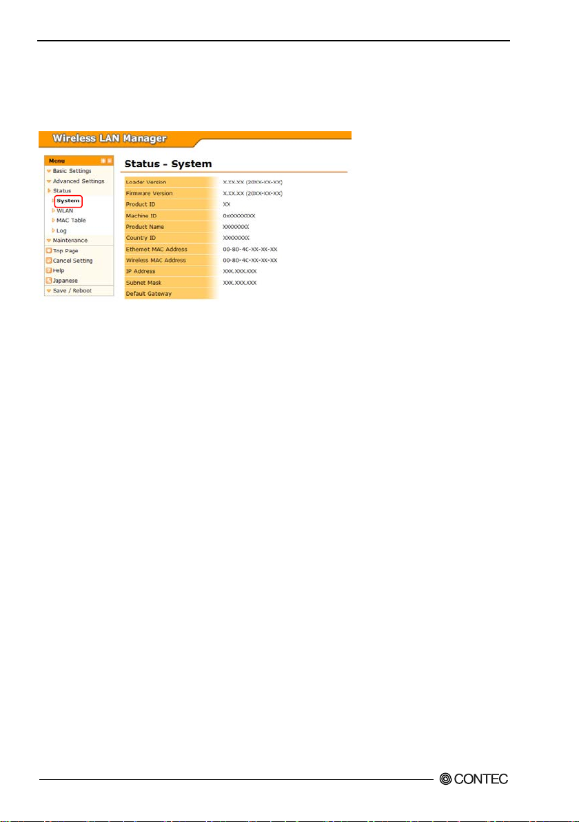
4. Setup and Status Display
Status Display
System
Load er Version
Show s th e loader ver s ion.
Firmware Version
Shows the firmware version.
Product ID
Show s th e product ID .
Machine ID
Shows the machine ID.
Product Name
Show s th e product name.
Country ID
Shows the country ID.
Ethernet MAC Ad dr es s
Shows the ethernet MAC address.
Wireless MAC Address
Shows the wireless MAC address.
IP Addr e s s
Shows the IP address.
Subnet Mask
Shows the subnet mask.
Default Gateway
This displays the IP address of the standard connected gateway. When not configured
(00-00-00-00-00-00), nothing is shown.
FXA2000-G
46
Page 54
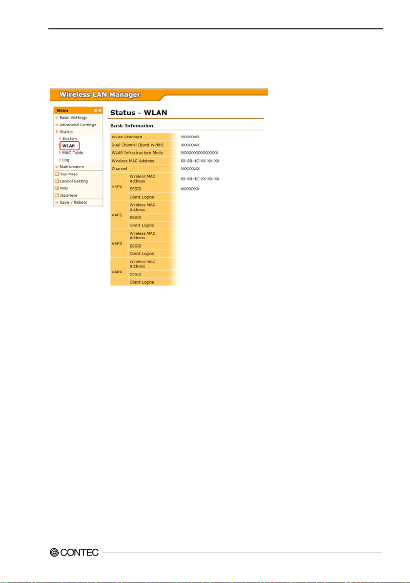
WLAN
▼Basic Information (Access Point)
Show n when the unit type is a ccess point .
4. Setup and Status Display
WLAN Standar d
Shows the configured wireless networking standard.
Dual Cha nnel (Bandwidth)
Shows the bandwidth when the configur ed wireless networking standard is IEEE 802.11n. When dua l
channe l m od e is disabl e d, 20 MHz is sho w n. When enabled, 40 MH z is sh own.
WLAN Inf rastr ucture Mode
Shows the configured wireless infrastructure mode.
Wireless MAC Address
Shows the wireless MAC address.
Channel
Shows the configured channel.
(VAP) Wireless MAC Address
Shows the wireless MAC address for each VAP. From VAP2 onward, the value is not displayed when
the VAP is disabled.
(VAP)ESSID
Shows the ESSID for each VAP. From VAP2 onward, the value is not displayed when the VAP is
disabled.
(VAP) Client Logins
Shows the number of client logins for each VAP. From V A P2 on wa rd, the value is not di s pl ayed when
the VAP is disabled.
FXA2000-G
47
Page 55
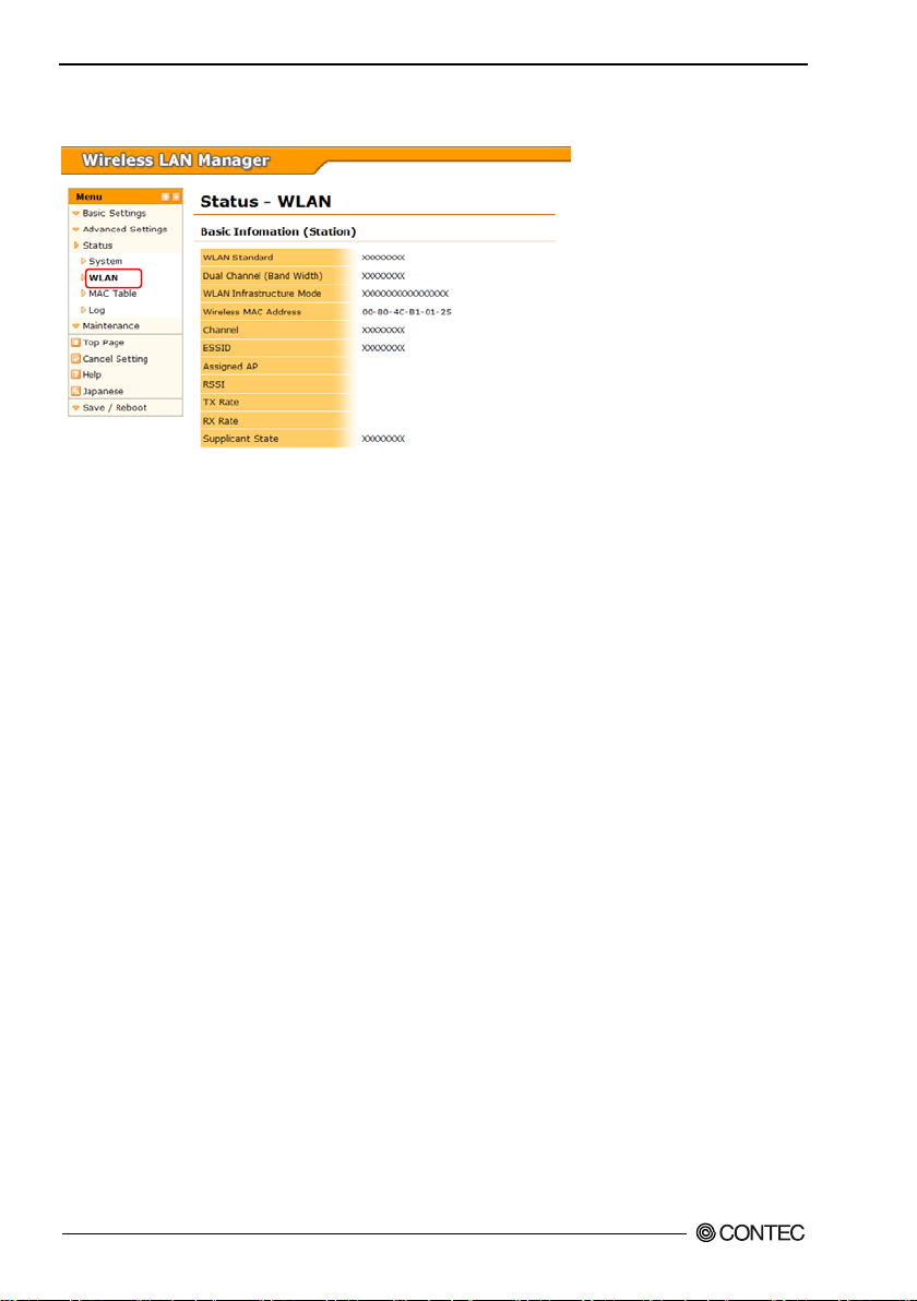
4. Setup and Status Display
▼Basic Information (Station)
Show n when the unit type is sta t i o n.
Wireless Networking Standard
Shows the current wireless networking standard. This is hidden when the device is not logged in to an
access poi nt.
Dual Cha nnel (Bandwidth)
Shows the bandwidth when the current wireless networking standard is IE EE 802.11n. When dual
channel mode is disabled, 20 MHz is always shown. When enabl e d, 20 MHz or 40 MHz is shown
depending on t he access poi nt settings.
Wireless Infr astructure Mode
Shows the configured wireless infrastructure mode.
Wireless MAC Address
Shows the wireless MAC address.
Channel
Shows the current cha nnel. This is hidden when the device is not logged in to an access point.
ESSID
Shows the configured ESSID.
Assigned AP
Shows the wireless MAC address for the access point currently logged in to.
This is hidden when the device is not logged in to an access point.
RSSI
Shows the RSSI which indicates the signal strength for the wireless connection for t he access poi nt
currently logged in to.
This is hidden when the device is not logged in to an access point.
TX Rate
Shows the TX Rate for the wireless conne ction for the access point currently logged in to.
This is hidden when the device is not logged in to an access point.
RX Rate
Shows the recept ion rate for the wireless connection for the access point currently logged in to. This is
hidden whe n the device is not logged in to an access point.
FXA2000-G
48
Page 56
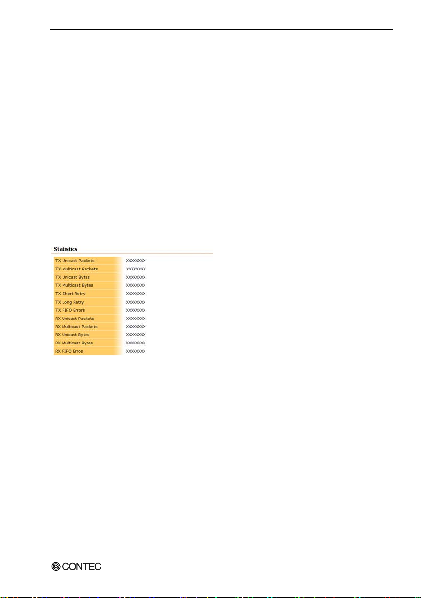
4. Setup and Status Display
Supplicant Aut he nt icat io n Status
Shows the authentication status for the authentication s upplicant in WPA and WPA2. "In valid(1)" is
shown w h e n not using a supplica nt. "Suc ce s s(2 )" is sho w n w he n w ireles s connectio n au thentica tion using
a supplicant was successful. "Failure(3)" is shown when authentication fails. "Authenticating(4)" is
shown during authentication.
Certificate Information
When the unit type is station, show s the value when the device was able to complet e the wire less
connection and a uthentication using encryption that uses a WPA or WPA2 authentication supplicant.
Certificate Information - Issuer
Shows the name of the certificate publisher (CA).
Certificate Information - Subject
Shows the name of the organization the certificat e was issued to.
Certificate Information – Vali d from
Valid from
Certificate Information – Valid to
Show s t h e d a te the cer t ifica t e expire s.
▼Statics Information
TX Unicast Packets
Displays the total number of unicast packets that transmitted.
TX Multi ca s t Packet s
Displays the total number of multicast packets that have been transmitted.
TXUnicast Bytes
Displays the total number of unicast bytes that have been transmitted.
TX Multicast Bytes
Displays the total number of multicast bytes t ha t have been transmitted.
TX Short Retry
Displays the nu m b er of times that pack et s have been r etr ansmitted one time.
TX Long Retry
Displays t h e n u m ber of times tha t pa ckets have be e n ret r ansmi tted mu ltiple t i m e s.
TX FIFO Errors
Displays the number of FIFO Errors th at occurred when transmitting data.
RX Unicast Packets
Displays the total number of unicast packets that has been received.
FXA2000-G
49
Page 57
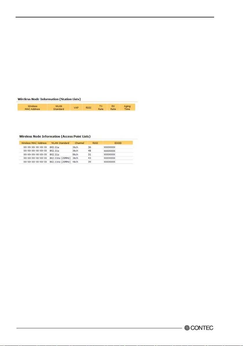
4. Setup and Status Display
RX e Multicast Packets
Displays the total number of multicast packets that has been received.
RX Unicast Bytes
Displays the total number of unicast bytes that has been received.
RX Multicast Bytes
Displays the total number of multicast bytes that has been received.
RX FIFO Errors
Displays the number of FIFO Errors that occurred when receiving data.
▼Wireless Node Information (Station List)
Show n when the unit type is a ccess point .
Shows a list of the stations logged in to the device.
▼Wireless Node Information (Access Point List)
Show n when the unit type is sta t i o n.
Shows a list of access points that the device wa s able to scan and confir m the existence of.
FXA2000-G
50
Page 58
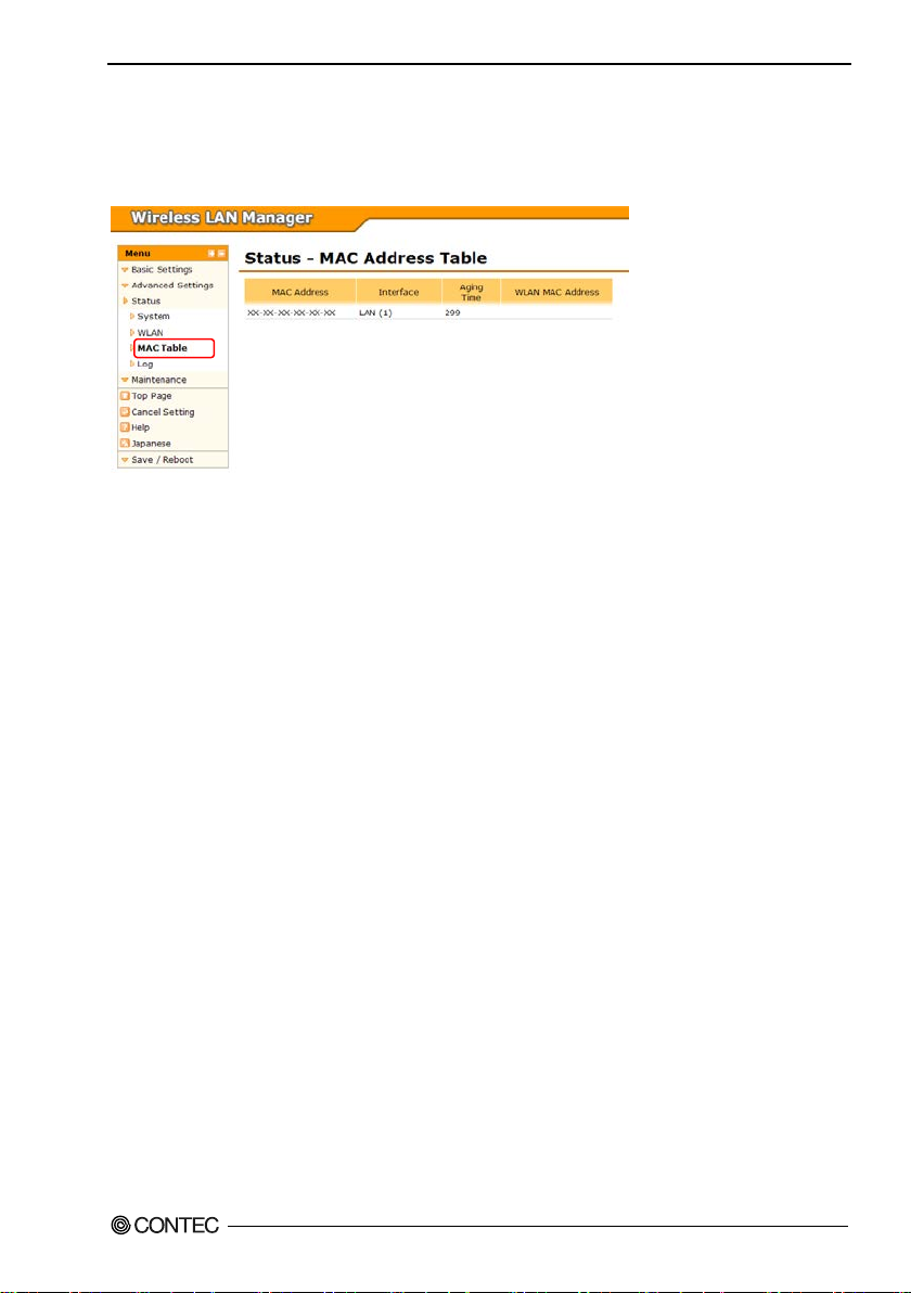
4. Setup and Status Display
MAC Address Table
Shows a list of MAC address the device has le arned of by communications over the w ired and wireles s
networks.
MAC A ddre sses
Shows the MAC addresses for this device and those of other le arned of devices.
Interface
Devices learned of via the wired network are shown as "LAN(1)" , dev ices learned of via the wireless
network are shown as "WLAN(2)".
Aging Time
Shows the aging time (expiration time) for the target device.
Wireless MAC Addresses
Shows the wireless MAC address of devices learned of via the wireless network.
FXA2000-G
51
Page 59
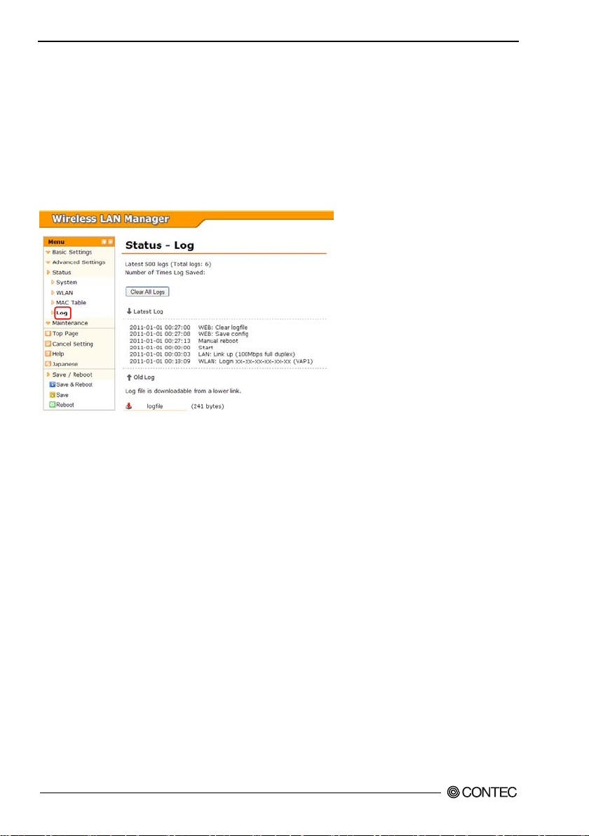
4. Setup and Status Display
Log Information
Shows the log recorded by the device.
If the n umber of log entries exceeds 500 entries, the mos t re ce nt 500 entries are displayed. If you wish to
check the entire log, open the li nk to the log file at the bottom of the page.
When the device's "Save Log" setting is enabled, the log in memory is regularly written to the unit's flash
ROM. The number of ti me s the log has been written to the flash ROM is displayed in "Number of Times
Log Saved" at the top of the page.
To delete the entire device log, click "Clear Log", and then click "OK" on the confirmation dialog. Use
caution as the log canno t be restored when cleared.
FXA2000-G
52
Page 60
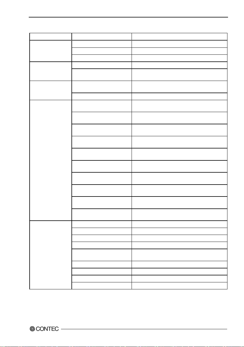
An explanation of the items recorded in the log is de tailed below.
ps full/harf
IP address lease for DHCP client (leased IP address &
WLAN: Login
WLAN: Roaming
WLAN: Logout
XX-XX-XX-XX-XX-XX (VAPX)
terminal MAC address & VAP)
WLAN: Login NG(2)
Login denied by client logins restriction (disconnected
WLAN: DFS Xch(XMHz) ->
XX-XX-XX-XX-XX-XX
al that failed
to authenticate)
WLAN: HT40X intolerant channel
Detected a congested channel detected before dual
WLAN: Switching band width from
Disabling dual channel mode because a congested channel
WEB: Setting clock (old time)
Setting the clock
WEB: Default setup
Setting defaults
WEB: Firmware update (XXX ->
Category Log conte nt Description
Start System Start Start
System
Wireless LAN
DHCP
Manual reboot Manual reboot
Switch: Init Initializing using the initialization switch
LAN: Link down Link down
LAN: Link up (100/10Mb
duplex)
DHCP: Lease X.X.X.X (Xh)
DHCP: No l ease An IP address for the DHCP client was not leased
XX-XX-XX-XX-XX-XX (VAPX)
XX-XX-XX-XX-XX-XX (VAPX)
XX-XX-XX-XX-XX-XX (VAPX)
WLAN: Login NG(1)
Link up (link s peed and communication mode)
lease time)
Login (wireless terminal MAC address & VAP)
Roaming (wireless terminal MAC address & VAP)
Logout (dis connected terminal MAC address & VAP)
Login denied by MAC addres s filtering (disconnected
4. Setup and Status Display
WLAN
WEB
XX-XX-XX-XX-XX-XX (VAPX)
Xch(XMHz)
WLAN: Auth Success
XX-XX-XX-XX-XX-XX
WLAN: Auth Error
(Xch)
20/40MHz to 20MHz
WEB: Set password Setting password
WEB: Save config Saving se ttings
XXX)
WEB: Server certificate upload Server certificate upload
WEB: Client certificate upload Client certificate upload
WEB: Private key upload Private key upload
WEB: Clear logfile Clear log
terminal MAC address & VAP)
DFS (original channel & new channel)
Authentication successful (MAC address of te rminal that
was succes sfully authenticated)
Authentication error (MAC address of termin
channel mode operation
was detected
Updated firmware (old version -> new version)
FXA2000-G
53
Page 61
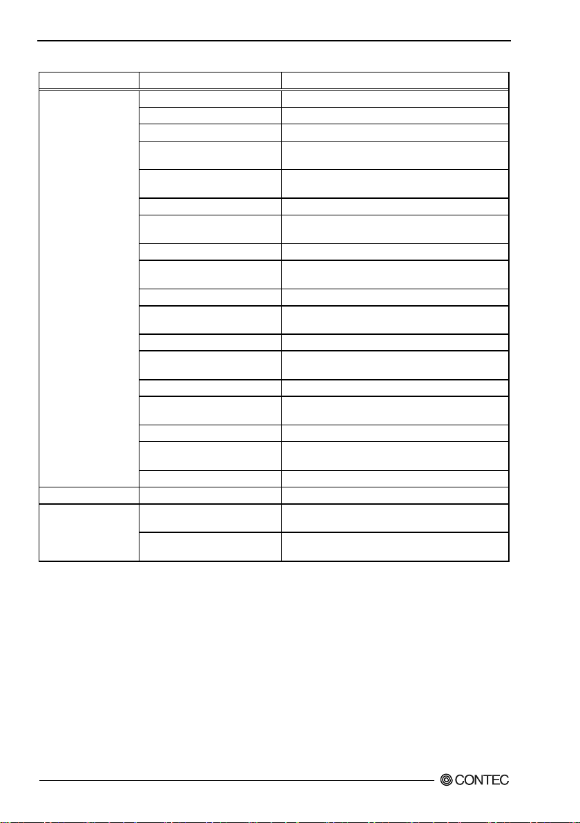
4. Setup and Status Display
Category Log conte nt Description
FTP: Firmware update
(XXX -> XXX)
Updated firmware
(old vers ion -> new vers ion)
FTP: Firmware update error
(States)
FTP: Config write error
FTP: Cconfig write error
FTP: Macfil write error
FTP: Server certificate write
error(States)
FTP: Private key write error
(States)
LDS: VAPX up
FTP: Login Login
FTP: Logout Logout
FTP: Login NG Login failed
Firmware update failed
FTP: Config write Writing configuration file
(States)
FTP: Cconfig write Writing encryption configuration file
FTP
Network time NTP: Setting clock (Old time) Setting time
link down sense
(States)
FTP: Macfil write Writing MAC address filter file
(States)
FTP: Server certificate write Writing server certificate
error(States)
FTP: Client certificate write Writing client server certificate
FTP: Client certificate write
FTP: Private key write Writing private key
FTP: RST command Reset command issued
LDS: VAP X down
(link down condition)
(link down condition)
Writing configuration file failed
Writing encryption configuration file failed
Writing MAC address filter file failed
Writing server certificate failed
Writing client certificate failed
Writing private key failed
VAP stoppe d by link down sense
VAP started by link down sense
FXA2000-G
54
Page 62
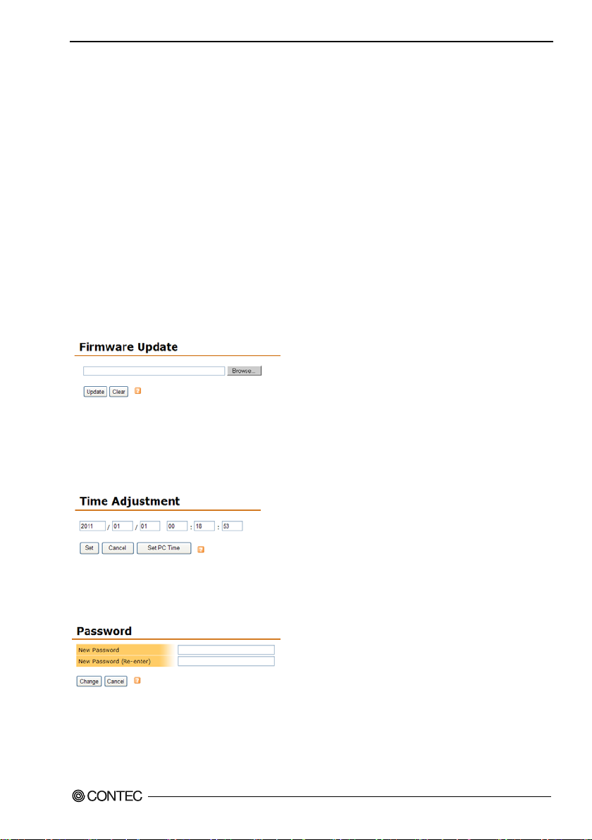
4. Setup and Status Display
Maintenance
Firm ware Updat e
You can update the firmware on the device.
Click the "Browse" button, sele ct the version update file system file, and then click the "U pdate" to
upload the file to the device. The file is uploaded and the update task finishes about one to one and a half
minutes after clicking the "Up date" butt on, then the pag e changes. After uploading the file finishes, th e
device start s with the over written firmware by restarting.
When the version update fails, check that the uploaded f ile is the c or rect file, and then t ry to update the
version again.
Do not turn off the device's power under any circumstances during the updating task from whe n the
"Update" button is clicke d until the screen chang es as this w ill result in malfunction.
The progress bar di s pl ayed during the up da te is a guide that in dicates the progress sta tus in terms of time,
it does not indicate the actual progress of the work. The pr ogress bar indi cates the completion time when
the gauge is full.
Do not turn off the device's power while the firmware is being uploaded until the screen changes.
Time Adjustme nt
Set the date and the time for the device. Enter the year as four digits, t he month, the day, the hour
(24-hour ti me), the minut e, and the seconds, and then click the update button. When the month and day
are a single digi t, a 0 is added and they are displayed as two digits. You c an e nter the values as either a
single digit or as two digits. (Ex am ple: 2011/4/1 0:0:0) Or click the "Set PC Time" button to set the
time in the PC's internal clock where the browser is open in the entry form.
Password
You can change the login password to this device including the Wireless LAN Manager (this
configuration web page). Enter the password as alphanumeric characters with a maximum length of 31
characters. The changed password is valid a ft er t h e d e vice resta rts.
FXA2000-G
55
Page 63
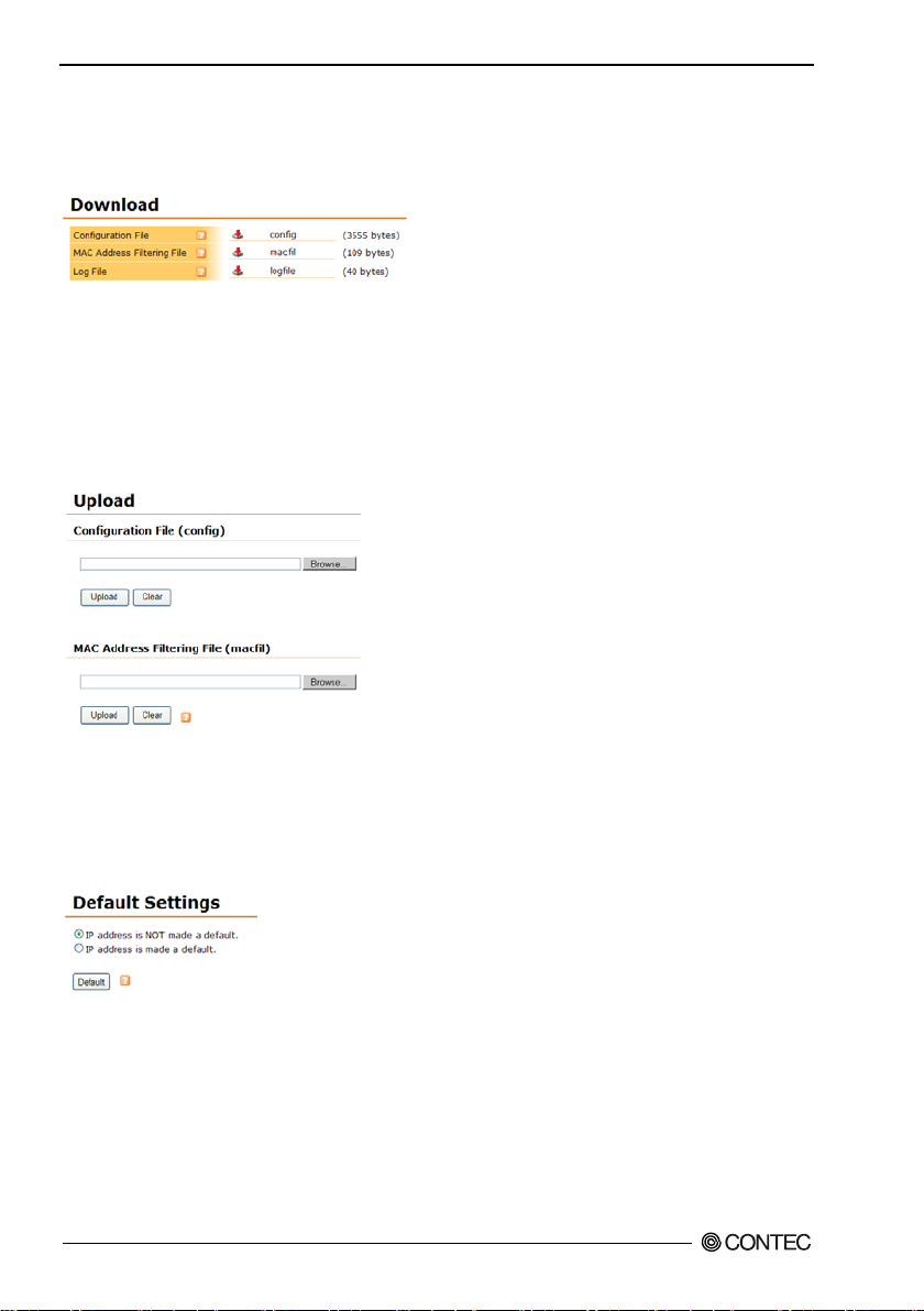
4. Setup and Status Display
Download
You can download the device's current configuration file and log file by clicking the link. If the file is
opened in the browser, right click on the li nk and sele c t the save to file item. The na m e o f do w nloaded
file has the extension .txt added to it.
Upload
You can update the device's configuration file (config) a nd MAC address filtering file (macfil). Click
the "Browse" button, select the file to be uploaded from each form, and then click the "Upload" to upload
the file to the device. The file is uploaded and the update task finishes several seconds or several t ens of
seconds after clicking the "Upl oad" button, then the page changes.
If the up load fails, check that the uplo aded file is the correct file, and then try uploading again. Do not
turn off the devic e's power under any circ um s tances during the updating task from when the "U pload"
button is clic ke d until the screen changes as this w ill result in malfunction.
Default Settin g s
You can restore the device's settings to the default settings. At this time, select with the radio button to
also restore the IP address e s (including subnet mask) to the defaults or to leave them as the y are. Then
click the "Default" button.
Even when the default setting s ar e re s t ored, the y are not save d t o t he de vice's configura t i o n f ile, so you
must save and res tart to reflec t the settings.
FXA2000-G
56
Page 64
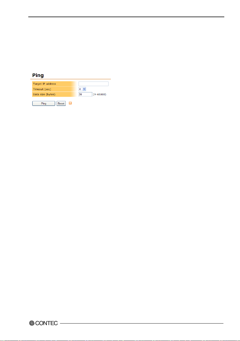
4. Setup and Status Display
Ping
You can ping to the specified IP address.
Enter the IP address of the ping to "Target IP Address".
Select the time to run a ping "Timeout (sec)". ping is done once per second, thi s time will be the number
of ping .
Set the ping data size to "Data Size (bytes)". Th is value can be set between 4 and 65000 byt es .
By clicking the "Ping" button, then the results displayed below the button.
FXA2000-G
57
Page 65

4. Setup and Status Display
FXA2000-G
58
Page 66
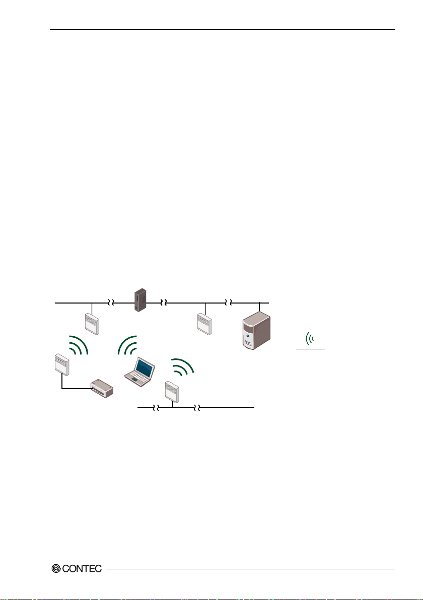
5. Wireless Link Mode and Wireless LAN Function
Net
wor
k A
Router
N
etw
ork
B
AP1 AP2
ST1
ST2
ST3
Netwo
rk C
HUB
FS
Net
wor
k B
:
:
Wireless connection
Wi
red con
nection
AP : Access point
ST : Station
FS : File server
5. Wireless Link Mode and Wireless LAN
Function
This chapter describes the major fu nctions of t he FLEXLAN series as a wireless LAN system and the
wireless link modes of the product along with configurati o n e xa m ples of net w or k s ava ilable in the
wireless link modes.
Wirele ss Lin k Mode
This product has three wireless link modes. The availabl e f unctions and network configurations differ
depending on t he mode. Use the wireless link mode most suitable t o the type of network you are
constructing.
The fa ctory default setting is “Advanced Infrastructure Mode”.
Chapters 3 and 4 describe the software setting procedures for t he wireless link modes and related it ems.
Standard Infrastructure Mode
In this mode, each access point (AP) can accommodate stations (ST) to m ake up a network.
This mode all ows the use of multiple APs to configure a wide-ar ea wireless LAN . All communication
betw een w i reless terminal s must go thr ou gh an AP.
Figure 5.1. Standard Infrastructure Mode
In the Standard Infrastructure mode above, all wir eless t ermina ls communic a t e via AP. Roaming
functions are support ed, allowing login to any AP within range of radio waves.
For the IP tunneling function to work properly, one of the APs must be setup as a master AP.
- Advantages
(1) Allows log-in restr ictions (security function).
(2) Improves secur ity using the WSL (Wireles s Security Link).
(3) When connectin g a CONT EC sta tio n to this pr odu ct usi ng a wire d conn e cti on, th er e is no limit
FXA2000-G
to prot oc ols and th e nu m b er o f d e vi ce s t ha t ca n be c onnected.
59
Page 67
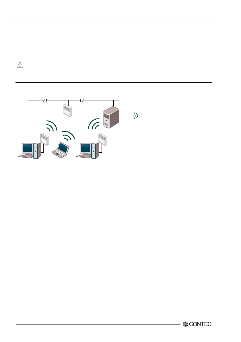
5. Wireless Link Mode and Wireless LAN Function
CA
UT
ION
Ne
t
wo
rk
A
AP
ST1 S
T2
S
T3
F
S
:
:
W
i
re
le
ss connection
W
ir
ed
co
n
ne
ct
i
on
AP
:
A
cc
es
s
p
oi
n
t
ST
:
St
a
ti
on
FS : File serv
er
Compatible Infrastructure Mode
This mode allows the product to be networked wit h other ma nufact u rers’ Wi-Fi cert ified wi reles s
terminals other than the F LEXLAN ser ie s. Communications between the wireless terminals are alw ays
made via the APs.
The Compatible Infra structure mode does not guarantee interconnection with Wi-Fi compl i a nt
products o f other man ufacturer s.
Figure 5.2. Compatible Infrastructure Mode
In the C o mpati ble Infrastructure mode, each wir eless te r m i na l perf orms co m munication via the AP a s in
the Standard Infrastructure mode. Roaming functions are supported, allowing login to any AP within
range o f ra dio wave s.
FXA2000-G
60
Page 68
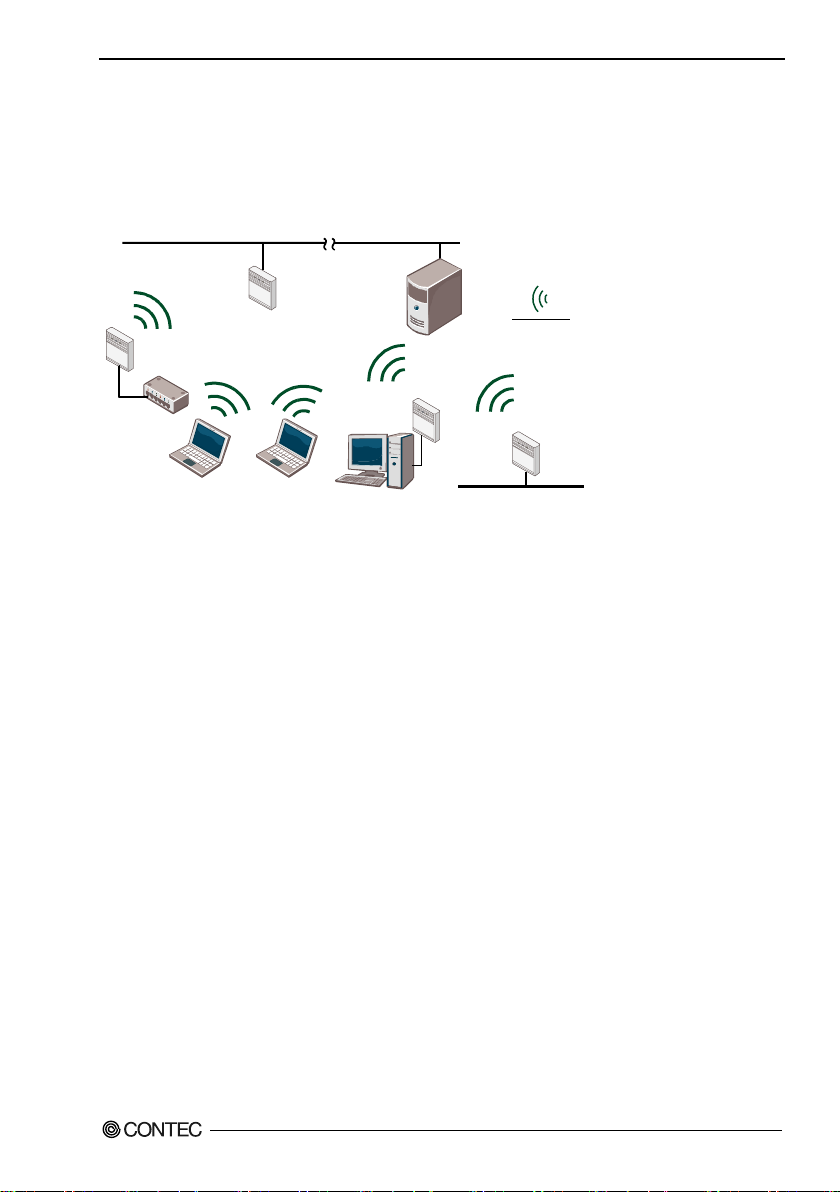
5. Wireless Link Mode and Wireless LAN Function
Ne
tw
o
rk
A
A
P
ST
2
S
T
3
F
S
:
:
W
i
re
le
s
s
c
on
ne
c
ti
on
W
ir
ed
co
n
ne
ct
i
on
AP
:
Ac
c
es
s
p
oi
n
t
S
T
:
S
ta
t
io
n
F
S
:
Fi
le
se
rv
e
r
H
UB
S
T4
ST
5
Networ
k
B
Advanced Infrastructure Mode
The Advanced Infrastructure mode is a mixture of the Standard Infrastructure and Compatible
Infras tructure modes . The Advanc ed Infrastructure mode can be used only when the product is configured
as an access point.
Figure 5.3. Advanced Infrastructure Mode
On the terminal set to the Standard Infrastructure mode, the FLEXLAN series' unique func tions ca n b e
used.
The terminal set to the Compatible Infrastructure mode serves as a simple bridge and thus the FLEXLAN
serie s’ unique fu nctions ca n no t be us e d on t hi s terminal.
61
FXA2000-G
Page 69
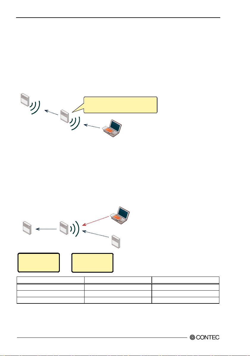
5. Wireless Link Mode and Wireless LAN Function
Access point
Repeater
Sta
ti
on
A
lth
oug
h th
e r
epe
ater is connecte
d
t
o another access
po
int
,
the
rep
ea
ter
its
elf
is
als
o a
n a
cce
ss p
oin
t,
so
wire
les
s L
AN
rela
ys
are
possible.
Access pointAccess point Repeater
Compatible Infrastructure
Standard Infrastructure
The station side is set
to "Standard
Infrastructure" mode.
The access point side is
set to "Advanced
Infrastructure" mode.
Wireless connection mode of repeater
VAP1 of repeater (AP side)
VAP2 of repeater (ST side)
Standard Infrastructure
Standard Infrastructure
Standard Infrastructure
Compatible Infrastructure
Compatible Infrastructure
Compatible Infrastructure
Advanced Infrastructure
Advanced Infrastructure
Standard Infrastructure
Repeater
What’s Repeater?
The repeater used with the wireless LAN is a function that operates the wireless LAN equipment as a pair
of virtual wireless LAN devices (VAP). One of these devices is se t as the acces s poin t and the other is set
as the station.
It is poss ible to co nnect to other access po ints from the station and to log in to the access point from other
stations.
Specification for Repeater and Wire less Connection Mode
When a piece of equipment is set as a repeater, its VAP1 becomes an access point and its VAP2 becomes
a station. In this situation, if you set "Wireless Conne ction Mode" to "Advanced Infrastructure", the
repeater's access point side will operate in "Advanced Infra structure" mode and the repeater's station side
will operate in "Standard Infrastructure" mode.
If you set "Wirele s s Connection Mode" to "Compatible Infrastr uc ture" , both the access point and the
station will op erate in "Compa ti bl e Infr as tru cture" mode. In this situatio n, th e multi -client function of
VAP2 (t he sta t ion) will b e forcibl y enabled.
If you set "Wirele s s Connection Mode" to "Adv a nced Infrastructure", you will be able to conne c t to
stations in "Standard Infras tructure" mode and to s tations in "Compatible Infrastructure" mode.
f you will only use CONTEC series devices to construct your system, we recommend that you operate the
repeate r in "Adv anced Infrastructure" mode.
FXA2000-G
62
Page 70
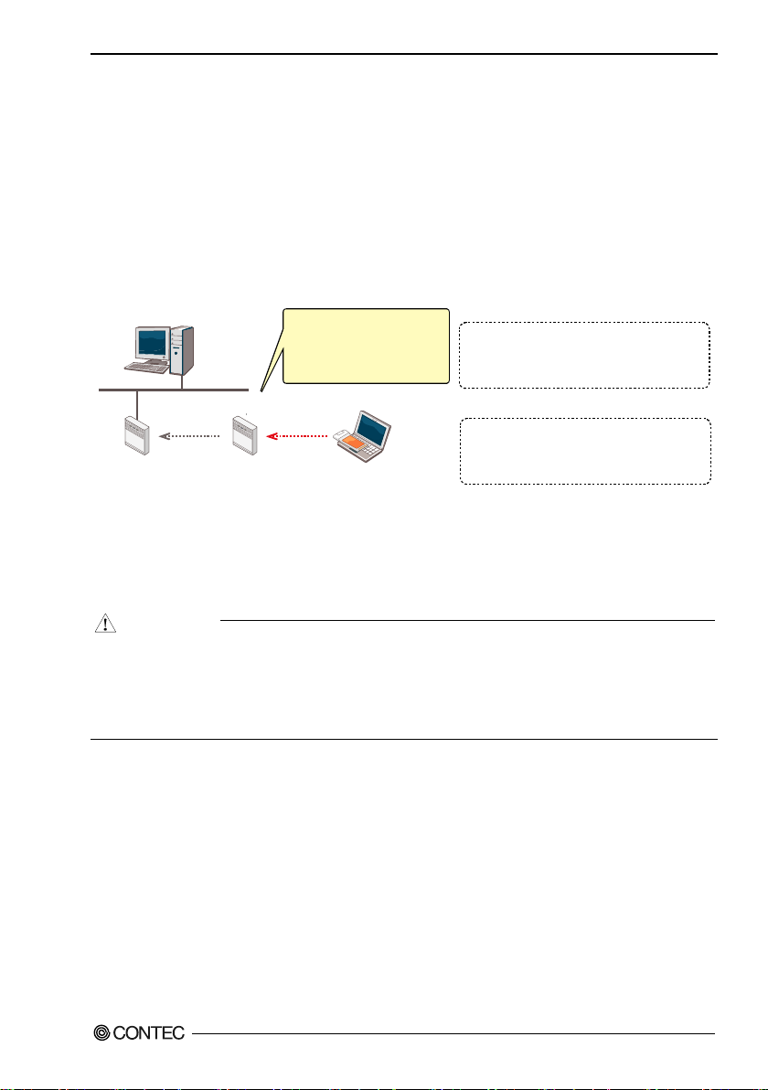
5. Wireless Link Mode and Wireless LAN Function
WLAN1
(Access point)
WLAN2 (Repeater) Cliant
PCI
192. 168. 1. 10
This is a multi-client station,
so all MAC addresses lower than
this device take on the wireless
MAC address of this device.
Compatible infr
ast
ructure
When set to "Advanced Infrastructure" mode
Interface : 192. 168. 1. 10 - 0x10006
Internet Address Physical Address Type
192. 168. 1. 1 00-80-4C-b0-00-01 dynam
ic
192. 168. 1. 2 00-80-4C-B0-00-02 dynam
ic
192. 168. 1. 11 B8-FF-61-15-37-47 dynam
ic
Interface : 192. 168. 1. 10 - 0x10006
Internet Address Physical
Address Type
192. 168. 1. 1 00-80-4C
-b0-00-01 dynam ic
192. 168. 1. 2 00-80-4
C-B1-00-02 dynam ic
192. 168. 1. 11 00-80-4
C-B1-00-02 dynam ic
When set to "Compatible Inf
rastructure" mode
19
2.
168. 1. 1
E 0
0-80-4C-B0-00-01
W00-80-4C-B1-00-01
192. 168. 1. 2
E 00-80-4C-B0-00-02
W00-80-4C-B1-00-02
192. 168. 1. 11
WB8-FF-61-15-37-
47
C
AUTION
Recommended Setting
When "Wireless Connection Mode" is set to "Compatible Infrastructure", the VAP2 (station side) of each
repeater located under this device is also set to "Compatible Infrastructure" mode. As such, all terminals
under the repeater have the same MAC ad dress in the PC1 ARP table.
In thi s situation, clients roam from WLAN2 to WLAN1, and communication cannot be performed from
PC1 to 192.168.1.11. The reason for this is that if a client connects to WLAN1, its MAC addr ess will be
changed.
To have PC1 perform communication, you have to delete the PC1 ARP table, and have PC1 learn the
192.168.1.11 MAC address aga in.
PC1 is linked to the client roamin g , s o t he PC1 AR P table cannot be d elete d. When you use repeaters to
construct your system, we recommend tha t you oper ate the repeaters in "Advanced Infrastructure" mode.
If AP s w ithout "Standar d I n frastru ctu r e " m ode made b y other com pa nies exist within your s y st e m,
you will not be able to use "Advanced Infrastructure" mode.
For example, if WLAN1 in the above figure is an access point made by another company and you set
WLAN2 to "Ad vanced Infras tructure" mode, WLAN1 and WLAN2 will not be ab le to c ommunicate
with each other.
FXA2000-G
63
Page 71
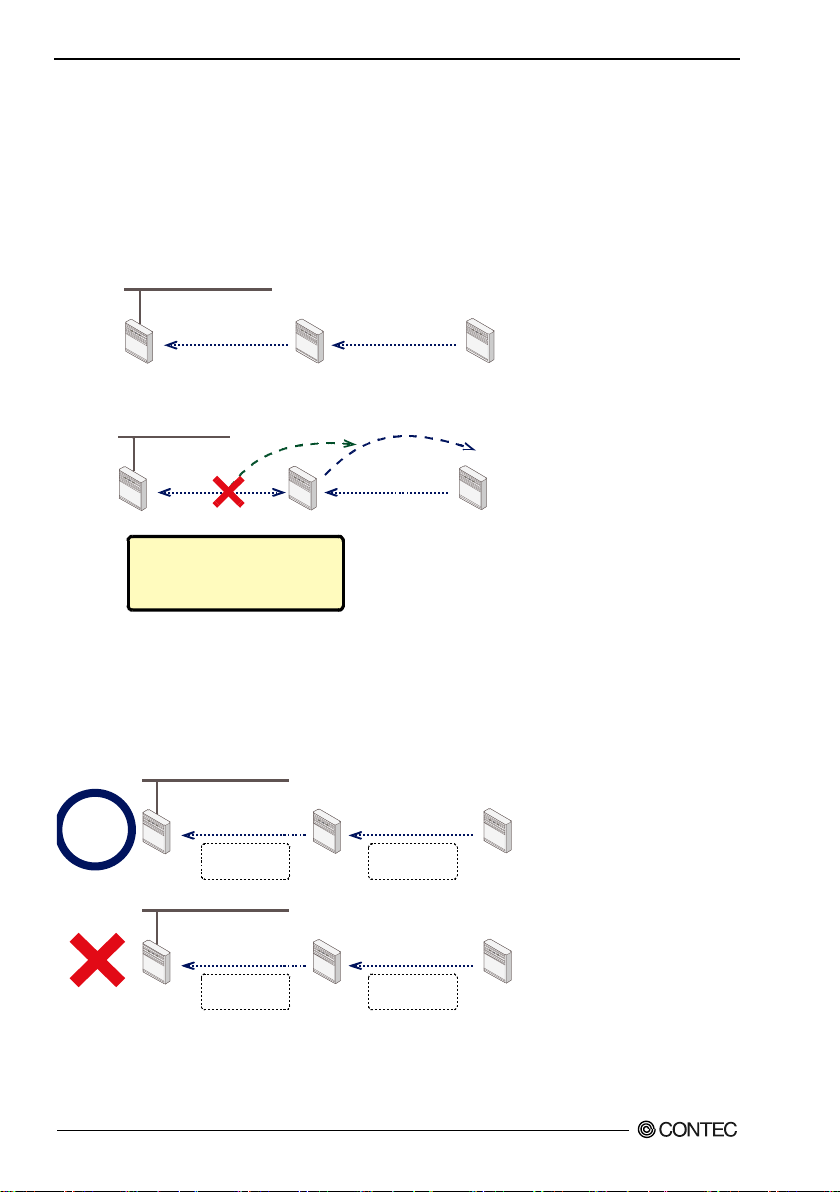
5. Wireless Link Mode and Wireless LAN Function
Access point Re
peater Repeater
Ac
ces
s p
oin
t Repeater Re
pea
ter
Ro
ami
ng
When a connection is di
sco
nne
cte
d
due to an access poin
t g
oin
g do
wn
or due to some
oth
er
rea
son
IEEE802.11n
(5GHz) 36ch
IEEE802.11n
(5GHz) 36ch
IEEE802.11a
36ch
IEEE802.11n
(5GHz) 44ch
Access point Repeater Repeater
Access point Repeater Repeater
Notes
When you configure the device to operate as a repeater, regardl ess of whether the network configuration
is chain or star, use the "Preferred AP" function to specify the connection destination access point.
Also, you have to set the "Connections to Non-Prefer re d A Ps" funct i o n t o "D isable" i n ord er to prev e nt
loops between repeaters with unauthorized connections to une xpected access points .
(1) Use the preferred access points to specify the connection destinations to establish an arbitrary
connecti on structure.
(2) If you do not fix the connection destinations, loops may occur between repeaters.
If you s et a device as a repeater , s et all parts of the wirele s s n et work to t h e same ch annel s and the sa me
wireless LAN standard.
For exa mp le, if you c on s tr u ct a network w ith one access point and two re p e a t ers for a tota l o f three pie c es
of wirele s s equipment, configure all th e equipment so that the same w ireless LAN st anda rd and the same
channels are used.
FXA2000-G
64
Page 72

5. Wireless Link Mode and Wireless LAN Function
Installation in a Network
This section de scri bes how to in stall th e FXA2000-G to construct a network with improved performance
and discu sses the general features a nd radio characteri stics of the wireless LAN as well as the guidelines
for constructing the network.
Features of th e Wi rele ss Network
In general, the operation of a wireless network is the same as for most other types of LAN. T he most
prominent feature of the wireless net work i s that it us es radio wave s as its mediu m , elim inati n g th e need
for cabling. The wireless network thus requires no cabling cost and has other advantages as listed
below
:
- Quick construction of a LAN
- Temporary installation of a LAN
- Higher flexibility in layout of connected PCs (terminals)
- Assured mobility of connected PCs (terminals)
On the other hand, the wireless network ha s the following drawbacks from the operati onal point of view
due to the na t u r e o f ra dio wave s
- Signal attenuation
- Signal interference
Also, although this unit does not require a radio license, it is subject to radio regulations.
:
FXA2000-G
65
Page 73
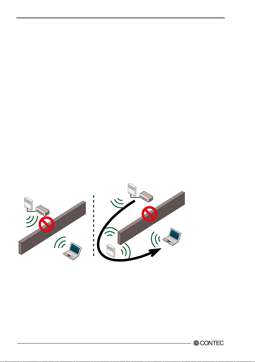
5. Wireless Link Mode and Wireless LAN Function
Operating Environment and Radio Waves
When usi ng this product to construc t a network, install and oper a te it consi dering the radio environmen t
to optimize t he perf orman c e.
Is allowed to use radio equipment at the installation location?
In some medical institutions an d laboratories, rad io-se nsitive precision instruments are used an d it may be
prohibited to use radio equipment.
Radio waves are at tenuated.
Although a radio wave is attenuated naturally as it travels fro m its transmission sou r c e, it may als o b e
attenuated by an object existing in its way. Major obstacles th at attenuate radio waves are as fo llow s
- Concrete wall
- Metal surfaces in the vicinity of the antenna
Obstacles blocking radio waves include metal walls and walls containin g a metal firewall.
Stric tly speaking, nearly all objec ts in the pat h of the radio waves (such as part itions or people) cause
some attenuation but these do no t have a significant impact on network performance.
RSSI (Receive Signal Strength Indication) utili ty is available as a means of knowing the sign al strength of
an incoming radio wave. Placing this product for a greater RSSI value makes the communication state
more stable. If the RSSI value is s ma ll a nd slightly m oving the p os it ion of the product does not increase
the RSS I value, it indica tes radio wave attenuation either to the distanc e or by an obstacle.
:
FXA2000-G
66
Page 74

5. Wireless Link Mode and Wireless LAN Function
Pay attention to radio interference.
Radio interference means the reception of radio waves in the frequency band used by this network that are
generated by equipment that is not part of the network to which this product belongs. Listed below are
major examples of sour ces of inter fering radio waves generated in general environment s excluding plants
and fact or ies
:
- 5GHz (if using IEEE 802.11n draft standard or IEEE 802.11a standard in the 5GHz band) or 2.4GHz
(if using IEEE 802.11n draft standard or IEEE 802.11b/IEEE 802.11g s tandard in the 2.4GHz band)
band wi re l e s s net w or ks that do no t c om ply with IE EE 8 02.11 .
- if using IEEE 802.11b/IEEE 802.11g standard in the 2.4GHz band. Ex . microwave ovens, security
gates (ins talled near the entrances of some departme nt stores and rental shops), copiers which give off the
2.4GHz ele ct r i c wave s.
Where there is a l arg e metal wall such as in a warehouse, the radio wave generated from the sender is
reflected, resulting in those radio waves reaching the receiver which have taken different routes (thereby
phase-shif ted). This has the s imilar effect as the generation of interferi ng radio waves, possibly slowing
down dat a tr a n s f er.
Most of the interfering radio wave sources other than wireless networks have local and/or temporary
effects, not so affecting network performance. Rarely, however, the date rate is reduced and, in the
worst case, communicati o n is disabled temporarily. In such cases, change the location of this product
and the cha n n el u s e d for c om municat ion. T his may sol v e the proble m .
FXA2000-G
67
Page 75
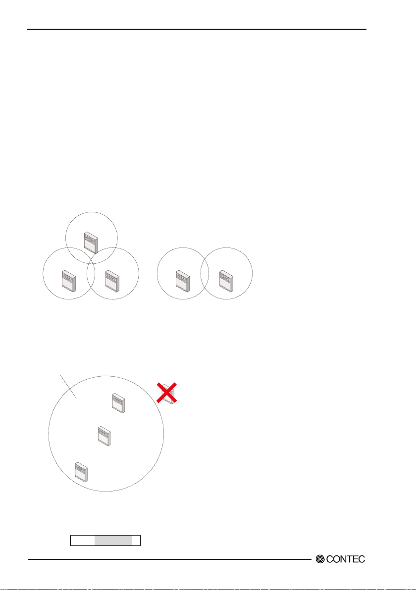
5. Wireless Link Mode and Wireless LAN Function
When using it in 2.4GHz
When using it in 5GHz
1ch
6ch 11ch 36ch 44ch
Cover area
ST2
ST1
ST3
AP
Constructing a Network
This section gives some pointers and cautions relating to construct ing a network using the AP a nd station,
and pro vi d e s so m e practica l e xamples .
(1) When using this product in the 5GHz band, any of the following channels ca n be set:
W52: channels 36, 40, 44, and 48
W53: channels 52, 56, 60, and 64
W56: channels 100, 104, 108, 112, 116, 120, 124, 128, 132, 136, and 140.
W58: channels 149, 153, 157, 161, and 165.
When usi ng in IEEE 802.11g (2.4GHz), channels 1 to 13, and in IEEE 802.11b (2.4GHz), channels 1
to 14 can be set.
Wireless communication is possib le wit h stations that support the a bo v e c ha nnels.
Using differen t channel s for wi r e l e s s network s a djacent t o ea c h other (In 5GHz band , set it to 36.44,
8ch or more apart and in 2.4GHz, 1, 6, 11 5ch or more apart) prevents radio interference and
improves the throughput of either network.
(2) Check the coverage (cover area) of the AP. To use the AP with two or more station logged in AP,
all the station must b e install e d with in the cov er area. The AP’s co vera ge varies wi t h obstacles
(concrete wal l s, i ron doors , elevator halls, etc .) . Note also that the number of transmission/reception
errors increases beyond a certain transmission distance.
When set ting up the network, chec k the RSSI le vel then confirm that communication works correctly
with the application you plan to use. For a TCP/IP system, for exampl e, you can use the Windows
PING command. T o use PING, start the command prompt (MS-DOS) and enter the following command.
The exa m pl e c ommand is fo r an AP wit h an IP addr e s s of 192.168.0.2.
FXA2000-G
68
ping 192.168.0.2
Page 76
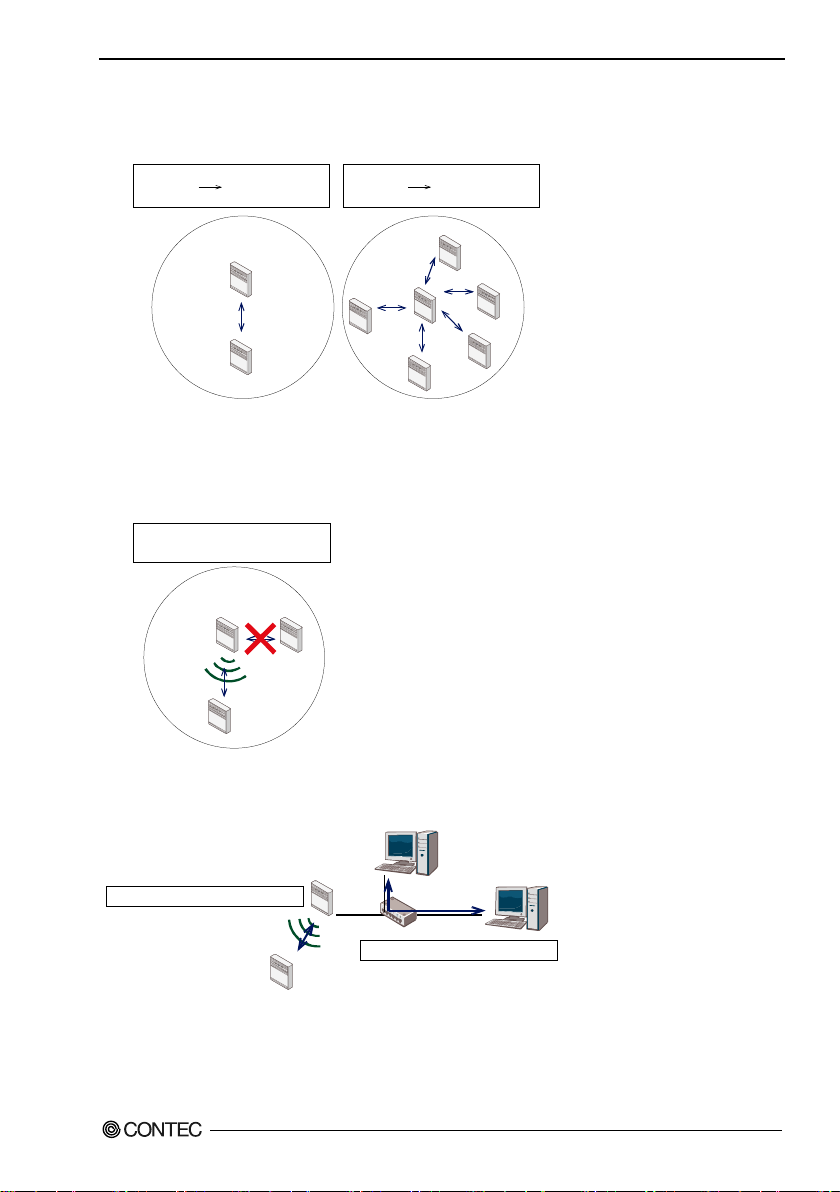
5. Wireless Link Mode and Wireless LAN Function
Small load
Low impact
on communication
speed
Large load
High impact
on communication
speed
AP
AP
ST1
ST1
ST3
ST2
ST4
ST5
AP
ST
1
ST2
Si
mul
tan
eou
s co
mmunication
i
mpo
ssi
ble
AP1
ST1
HUB
PC1
PC2
Slower communication speed
Faster communication speed
(3) Two or more stations can log in the AP at the same time However, remember that the
communication speed slows due to the increased loading as the n um ber of user units for a pa rticular
AP increases.
(4) If a pair of wireless terminal s are commu nicat ing via a particu l a r ch annel , no other commu nicat ions
can use that channel within the range of the r a dio signal (the exception is bro a dcast ing which
transmits to all terminals). As a result, communication speed tends to drop as the density of
wireless terminals increases although this depends to a large extent on how frequently the network is
used.
(5) If the AP is connected to an Ethernet hub or similar, a unexpectedly la rge load can occur on the AP if
the Ethernet traffic is heavy and thi s may redu ce the perfor ma nce of th e wirel ess net w or k. This can
be solv e d by changing t h e hu b connect e d to the AP to a switching hu b ( br i dge).
(6) Setup the software in accordance with how t he network will be used.
FXA2000-G
69
Page 77

5. Wireless Link Mode and Wireless LAN Function
A
P1
3
m
or
mo
re
A
P2
S
T1
S
T2
1m or
m
or
e
(7) The c ommunicati o n sp e ed may also drop due to interference if two wireless terminals are lo cated
close to each other. In general, maintain a gap of about 1m between station, 3m between APs and
station, and 3m between APs.
(8) The best performance is achieved from antennas if they are located in an open space free fr om
obstructions. Avoid locating antennas where they will be hidden. In par ticular, when
communication distance is an important consideration, i t is recommended that you install antennas in
a high location with a clear view.
(9) Floors often c onta in ste el beam s or metal f ire wa ll s and ther ef or e co mmu nic a tio n bet ween flo or s is
often not possible.
FXA2000-G
70
Page 78

6. Maintenance
CAUTION
6. Maintenance
This chapter des cribes h o w to p erform ma i ntenan ce on the AP and explains the tools to be used. Here,
“maintenance” means the following
the software settings.
log file collection, firmware upgrades, and saving and restoring
:
Maintenance Tool
This maintenance tool is available for the FTP, Web browser and FLEX HEL PER. T his sectio n
describe s how to use the tool by the FTP. For details about downloading using a Web browser, see the
section titled "Download" in Chapter 4 "Setup and Status Display".
For details and applica tions of FLEX HELPER, conta ct your dealer.
Log File Collection
To collect the log file, you collect it by us i n g Web brow s er or FTP via the LAN .
The log file is in text format and can be displayed in the Notepad or WordPad programs that come with
Windows.
The collected log file is stored the CF card with the following file name.
File name
To collect the log file, log collection m ust be enable d. Note a lso that the contents of th e log file
differ depending on the operating mode and software setti ngs.
LOGFILE
:
FXA2000-G
71
Page 79
6. Maintenance
C:¥>cd D:¥tmp
………… (1)
Using FTP to Get th e Lo g Fi le
Log files that use the FTP are collected according to the follo w in g procedu re.
(1) Move t o the folder in which you wish to save the file.
(2-1) Run FTP to log in to the AP.
(2-2) Run FTP to log in to the AP. (Ent er FT P user’s name)
(2-3) Run FTP to log in to the AP. (Ent er FTP passw ord)
(3) Transfer the l o g f ile.
(4) Ex it FTP.
The fol lowing is an example for the time when Wi ndow s Command Prompt (MS-DOS Prompt) is used.
In this example, th e f ile will be m oved to the saving fol d er D
connecting to this product via FTP. The example assumes the User as admin (blank is OK), Password as
Pass (initial settin g) and the IP address as 192.168.0.1.
¥tmp and LOGFILE will be collected after
:
D:¥tmp>ftp 192.168.0.1
User (192.168.0.1:none)):admin
Password:pass
ftp>get LOGFILE
ftp>bye
* For details about downloading us ing a Web browser, see the se ction titled "Download" in Cha pter 4
"Setup and Status Display".
FXA2000-G
72
………… (2-1)
………… (2-2)
………… (2-3)
………… (3)
………… (4)
Page 80
6. Maintenance
C:¥>cd D:¥tmp
………… (1)
Saving the Settings File
Making a backup of the AP software settings file has the following benefits
- If you have more than one AP and all APs have the same settings, you just need to setup one AP then
use the resulting settings f il e for the other APs. (However, as this sets the same IP address for all
APs, you need to change the IP address separately.)
- The ol d s et ting s can be res t o r e d easily if a fault cause s the setti ngs fil e t o be erased.
The settings file is stored the CF card with the following file name.
File name --- --- --- --- --- CONFIG
If the MAC address filtering is used, it’s settin g f ile shoul d al s o b e sa v e d. T he setting file is store d in
memor y o n t h e AP wi th the foll o wing file name
MAC address filtering --- MACFIL
The fil e is in the memory even when the M AC a ddress filterin g function i s not in use It, ho we v er , does
not hav e to be saved.
:
Using FTP to B ackup the Settings File
Configuration files that use the FTP are collec ted according to the fol lowing procedure.
(1) Move to the folder in which you wish to save the file.
(2) Run FTP to log in to the AP.
(3) Transfer the settings file (CONFIG).
MACFLIST is also transferred if necessary.
(4) Exit FTP.
The fol lowing is an example for the time when Wi ndow s Command Prompt (MS-DOS Prompt) is used.
In this example, th e f ile will be m oved to the saving fol d er D
be collected after connecting to the product via FTP. The example assumes the IP address as
192.168.0.1.
¥tmp and CONFIG and MACFLIST will
:
:
* For details about downloading us ing a Web browser, see the se ction titled "Download" in Cha pter 4
FXA2000-G
D:¥tmp>ftp 192.168.0.1
User (192.168.0.1:none)):admin
Password:pass
ftp>get CONFIG
ftp>get MACFIL
ftp>bye
"Setup and Status Display".
………… (2-1)
………… (2-2)
………… (2-3)
………… (3)
………… (3)
………… (4)
73
Page 81
6. Maintenance
C:¥>cd D:¥tmp
………… (1)
Restoring the Software Settings
The software settings of this product can be recovered by using the saved setup file.
Using FTP to Restore the Setti n gs
Follow the procedure below to recover th e s oftware settings using FTP.
(1) Move to the folder with file.
(2) Run FTP to log in to the AP.
(3) Tr a ns f er t h e s ettings file(config).
MACFLIST is also transferred if necessary.
(4) Issue the reset request command (command
(5) Quit FTP.
The fol lowing is an example for the time when Wi ndow s Command Prompt (MS-DOS Prompt) is used.
In this example , the file will b e moved to the folder with fil e D
be transferred after connecting to the product via FTP. The example assumes the IP address as
192.168.0.1.
qu ote crst).
:
¥tmp and CONFIG and MACFLIST will
:
D:¥tmp>ftp 192.168.0.1
ftp>put CONFIG
ftp>put MACFLIST
ftp>quote rst
ftp>bye
The rese t request command s hown in (4) is a command used to reboot the product. There is no problem
to skip (4), stop FTP in (5) and reboot the product l ater.
FXA2000-G
74
………… (2)
………… (3)
………… (3)
………… (4)
………… (5)
Page 82
6. Maintenance
C:¥>cd D:¥tmp
………… (1)
C
AUTION
Upgr ad ing the Firmware
The AP firmware may be upgraded to resolve any bugs found in the software or to a dd new funct ions.
Contact CONTEC via our web sit e for d etail s of the lat e st fir mware .
The firmware is stored the AP memory with the following file name.
File name
This fil e can be writ ten over to u pgr ade the ve rsion of the firmwar e.
There are two ways to upgrade the vers ion of the firmware
Web set up scr een.
APFIRM.BIN
:
FTP; and Access Point Manager with a
:
Performing an Upgrade Using FTP
Follow the procedure below for the firmware version up setti ngs using FTP.
(1) Move to the folder with file.
(2) Run FTP to log in to the AP.
(3) Change the tr ans fer mode to binary.
(4) Transfer the firmware file APFIRM.BIN.
(5) Issue the reset request command (quote crst).
(6) Quit FTP.
The following is an example for the time when Wi ndow s Command Prompt (MS-DOS Prompt) is used.
In this example, the firmware file for version up will be moved to the folder with file D
APFIRM.BIN will b e transferred after connecting to the product via FTP. The example assumes the IP
address as 192.168.0.1.
¥tmp and
:
* For details about downloading us ing a Web browser, see the section titled "Download" in Chapter 4
T he s etup file data a n d firmwar e da ta may be damaged an d th e pr o du ct may no t op er a te proper l y i f it
FXA2000-G
D:¥tmp>ftp 192.168.0.1
ftp>bin
ftp>put FIRMWARE.BIN
ftp>quote rst
ftp>bye
"Setup and Status Display".
is rebooted or switched off while the firmware is still being updated (data being written).
………… (2)
………… (3)
………… (4)
………… (5)
………… (6)
75
Page 83
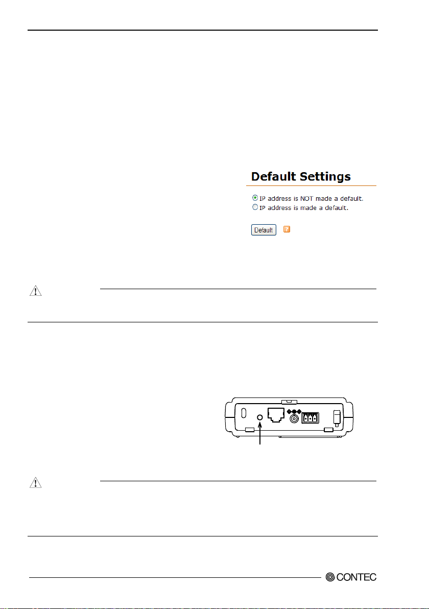
6. Maintenance
(1) Follow the procedure below when using Web browser to
CA
UTION
INIT button
INIT
5VDC
10/100M
LAN
5-30VDC
Vi-FG Vi+
CAUTION
Initialization
There are two ways t o initialize this product (recovering the factory settings).
- Using a W e b browser
- Using t h e INI T s witch of th e main unit
Each initialization method is described below.
Using a Web Browser
Follow the procedure below when using Web browser to initialize the pr o duct.
initialize the product.
(2) Select “Maintenance” - “Default set ti ng” from the menu.
(3) To leave the IP a ddress of the product unc hanged without
initialization, tick “Do not set IP address to default”. To
initialize the IP address, tick “Set IP address to default”
and the n cl i ck “Default”.
(4) Click “Save/Reboot” on the menu to save th e default
setting and reboot the product.
If the default setting is sel ected by mistake, click “Logout” on the menu to close the Web setu p
screen.
Using the INIT Switch of the Main Unit
Follow the procedure below when using the INIT S witch of the Main Unit to initialize the pr o duct.
(1) The LEDs of POWER, LAN and WLAN
continue to blink for a little while after INIT
swit ch is pushed.
(2) Relea se this button a fter the LED starts
flashing but before it reverts to an ON state
(an interval of approx. 3 seconds).
(3) All the settings a re restored to the default
settings after the product is started next time.
T he f la s hing cont i nues for a little while after th e pr o du ct is released during initialization by pushing
the INIT switch. This indicates internal memory files are being deleted. The internal memory fi l e s
may be dama ge d and the product may not start up properly if the power is sw it c hed off before the
flashing stops. Always reboot the product after the flashing stops.
FXA2000-G
76
Page 84

7. Troubleshooting
7. Troubleshooting
This chapter des cribes c o m mo n problem s tha t ma y oc cu r wi t h this product and what to do about them.
If any problems occur that are not described here, check to confirm that the re-occur, then contact the
retailer.
When Communication Fails
Chec k wired LAN comm unication
Chec k the wired LA N communication between this product and the connected PC.
- Check th a t the LAN cable is conn e c t e d corre ct ly.
- Chec k if the IP addresses and subnet masks of the prod uc t and PC are set correct ly.
- The communication with this product is not possible unless th e TCP/IP protocol is in stalled in the
PC.
Check w irele s s L A N co mmunicati on
If no problem is detected in the wi red LAN communicat ion between the product and PC, check the
wireless LAN comm unication between the produc t and access point.
- The FLE X L AN s eries is des igned to ha n dle a variety of operating formats, and requir es software
setting for eac h type of operation. Check that the se ttings are appropri ate for the type of operation,
and check the format in which communication is being attempted. Also check DIP switch sett ings.
- The termina ls that ca n n o t co mmunicate with each other may ha ve the sam e E S S I D . Two t ermina ls
with th e sa m e E SSID cannot co mmunicate with each other.
- Check w h ether the wire less lin k m o d e has bee n s et correctly. The wireless link mode of the s tation
(slave sta tion) mu st support t he wireless li nk m o de set on thi s product .
- Check w h ether c ommunicati o n i s r e s t r icted by s e curity functions such as the MAC address filtering.
- Check whether the data encryption se tting is the same as that of the recip ient.
Communication cannot b e p erformed w hi l e data encr y ption is be ing swit ch e d be tween ON ( enabled)
and OFF (disabled).
Check the peripheral environment and place of installation
- A nearby source of electro magne tic interfer e nce can prevent c o mmuni ca tion . In gener a l locations
(excluding factories) the following may be sources of electromagnetic emissions.
- 2.4GHz band wireless network not conforming to wireless LAN (IEEE802.11a/b/g/n).
- When u sin g by 2.4GH z ba nd, elect r ic device s w hich give off 2.4GHz ba n d e lectric wave microw ave oven, security gate (it is a antitheft gate in the shop ) , copy machine and so on.
Most electromagnetic sources other than wireless networks are local and not continuous, and therefore by
moving the locat ion of the unit and waiting briefly, c ommuni cation ma y be possibl e .
FXA2000-G
77
Page 85

7. Troubleshooting
- Somet imes communication is hindered by attenuation of elect ric waves . Attenuation occurs
naturally as distance from the source of transmission increases, but may also be caused by objects in
the path of the transmission. The objects primarily resp onsible f or attenuation are the following.
- Concrete walls
- Metallic s urfaces around this product
Setup Screen Unavailable on Web Browser
- Check if commu nication is possible between the product and PC.
- If no problem is detected in the communication between the product and PC, it may be related to the
browser settings. For the browser settings, see Chapter 3 “Connectio n to Devices and Setup
Methods”.
When the AP Will Not Start
Check the LED
- Check whether the “POWER” LED i s illu mi nat ed. If it is no t il l u minat e d, ch eck th e po w er cabl e
and make s ure that it is connected correctly to the pow er jack and the socket.
- Check whether the Power LED is flashing. I f the power LED is still fla shing more than 5 minutes
after the power is switched on, the problem may be an AP firmware failure.
In this case, the problem may be a startup error caused by corrupt data in the memory of this product.
If you cannot restore it, contact your retailer.
Chec k the power
- If using an AC adapter, check that the adapter is an optional accessory of a type specified by
CONTEC. Only use AC adap t er s sp e cified by CO NTEC wit h t his produ c t.
- If su pplying power from the power connector, check the power supply connection, supply voltage,
etc., and make sure that there are no problems. For de ta i l s a bou t conne ct i n g the power supply, se e
Chapter 2 "Setup".
FXA2000-G
78
Page 86
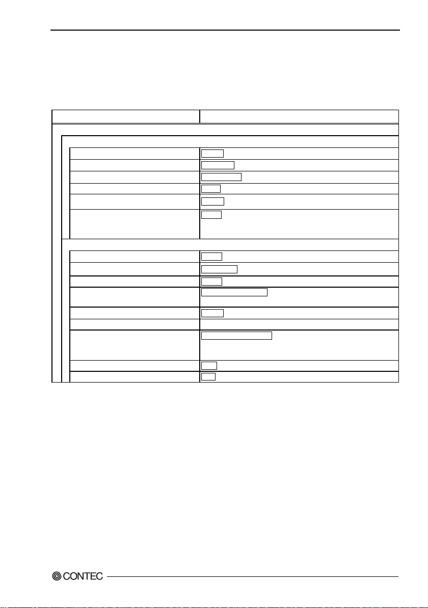
8. Appendix
Network
192.168.0.1
Default Gateway
0.0.0.0
EST+5, EDT+4, CST+6, CDT+5, MST+7, MDT+6, PST+8, PDT+7,
2,
Radio
Repeater Independent
Enable, Disable
IEEE802.11n (2.4GHz), IEEE802.11n (5GHz),
Channel *3
Varies de pending on the country in which the product is used.
Advanced Infrastructure*3
Compatible Infrastructure,
TX Power
MAX, 50%, 25%, 12%
Antenna *4
Auto, F ixed (Antenna :1)
Factory Default Settings List
Table 8.1 Initial Setting List (1/11)
Item Specification
Basic setting
8. Appendix
DHCP Client
IP Address
Subnet Mas k
Language
Time Zone
WLAN Interface
Unit Type
WLAN Standard
Dual Channel Mode *2
WLAN Infrastructure Mode
*1 : This setting is available when the unit type is "Station".
*2 : This setting is available when the unit type is "Access Point" or "Repeater" and the wireless networking standard is
"IEEE802.11n(5GHz)" or "IEEE802.11n(2.4GHz)".
*3 : This setting is available when the unit type is "Access Point" or "Repeater".
*4 : This setting can only be configured when the wireless networking standard is "IEEE802.11a", "IEEE802.11b", or
"IEEE802.11g".
Disable, Enable
255.255.255.0
English, Japanese
AKST+9, AKDT+8, HAST+10, WET+0, WEST+1, CET-1, CESTEET-2, EEST-3, TST-8, CST-8, KST-9, JST-9
Enable, Disable
Access point , Station, Repeater
IEEE802.11a, IEEE802.11b, IEEE802.11g, Auto*1
Disable, Enable
Standard Infrastructure,
FXA2000-G
79
Page 87
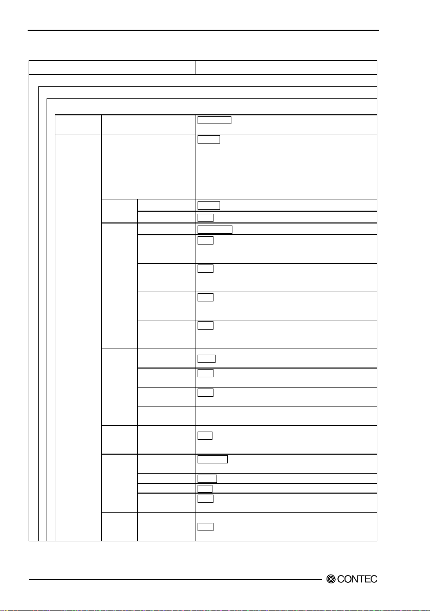
8. Appendix
Basic Settings
LocalGroup, (between 2 and 32 characters in length,
single-byte alphanumeric characters only)
Disable, WEP(Open), WEP(Shared Key), WEP (Auto) *5,
WPA-AUTO-PSK(AES) *5
Key
None , When set to None, the setting is disabled
hexadecimal value, 152bit : a 32 digit hexadecimal value
None , When set to None, the setting is disabled
hexadecimal value, 152bit : a 32 digit hexadecimal value
None , When set to None, the setting is disabled
hexadecimal value, 152bit : a 32 digit hexadecimal value
None , When set to None, the setting is disabled
hexadecimal value, 152bit : a 32 digit hexadecimal value
Authentication
Type
None Up to 32 characters in length, single-byte alphanumeric
characters only
None Up to 32 characters in length, single-byte alphanumeric
characters only
Certificate
Registration
WPA
*10
Group Key
(sec)
Interval (sec)
0(Disable)
0(Disable) or 120 - 259200
Server IP Address
0.0.0.0
Server Port
1812
None Up to 64 characters in length, single -byte alphanumeric
characters only, no spaces
*12
Table 8.1 Initial Setting List (2/11)
Item Specification
VAP Settings
VAP1
VAP Settings ESSID
Encryption
AES, IEEE802.1X(WEP) *6, WPA(AES) *6, WPA(TKIP)*6,
WPA-PSK(TKIP), WPA-PSK(AES), WPA2(AES) *6,
WPA2(TKIP) *6, WPA2-PSK(AES),
WPA2-PSK(TKIP),WPA-AUTO(TKIP)*5,
WPA-AUTO(AES) *5, WPA-AUTO-PSK(TKIP) *5,
WSL*7
Key
Setting *8
Encryption
Settings
Supplicant
Settings
*9
Settings
RADIUS
Server
Settings
*11
PSK
Settings
Function
Default key
Fixed Key 1
Fixed Key 2
Fixed Key 3
Fixed Key 4
User Name
User Password
Updating Interval
Recertification
Shared Secret
WPA Pre-Shared
Key (PSK)
FXA2000-G
80
Disable, Enable (Type2)
None a 20 digit hexadecimal value (0 to 9, a to f or A to F).
Fixed Ke y 1, Fixed Key 2, Fixed Key 3, Fixed Key 4
64bit : a 10 digit hexadecimal value, 128bit : a 26 digit
64bit : a 10 digit hexadecimal value, 128bit : a 26 digit
64bit : a 10 digit hexadecimal value, 128bit : a 26 digit
64bit : a 10 digit hexadecimal value, 128bit : a 26 digit
PEAP, EAP-TLS
Server certificate, Client certificate, Private key
3600
0(Disable) or 120 - 259200
None Alphanumeric characters between 8 and 63 characters.
Page 88

8. Appendix
*5 : This setting is available when the unit type is "Access Point ".
*6 : This setting is available when the unit type is "Access Point" or "Station".
*7 : This setting is available when the wire less connection mode is "Advanced Infrastructure" or "Standard
Infrastructure".
*8 : This setting is available when the encryption is set to either "WEP(Open)", "WEP(SharedKey)", "W EP(Auto)", or
"AES".
*9 : This setting is available when the unit type is "Station " and the encryption is set to either "WPA", "WPA2",
"WPA-PSK", or "WPA2-PSK".
*10 : This sett ing is available when the unit type is "Access Point " or " Repeater" and the the encryption is set to either
"WPA", "WPA2", "WPA-PSK", or "WPA2-P SK".
*11 : This setting is available when the unit type is " Access Point " and the encryption is set to either "IEEE802.1X",
"WPA", or "WPA2".
*12 : This setting is available when the encryption is set to either "WPA-PSK", or "WPA2-PSK".
FXA2000-G
81
Page 89
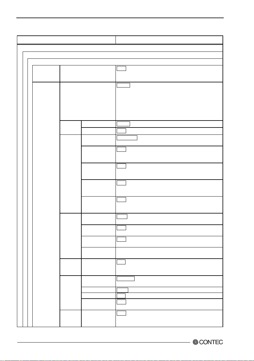
8. Appendix
Basic Settings
VAP Settings
VAP2*13
None , (When set to None, the setting is disabled, between 2
characters only.)
Disable, WEP (Open), WEP(Shared Key), WEP (Auto) *14,
WPA-AUTO-PSK(AES)*14
Function
Disable, Enable(Type2)
Key
None a 20 digit hexadecimal value (0 to 9, a to f or A to F).
Fixed Ke y 1, Fixed Key 2,
Fixed Key 3, Fixed Key 4,
None , When set to None, the setting is disabled
hexadecimal value, 152bit:a 32 digit hexadecimal value
None , When set to None, the setting is disabled
hexadecimal value, 152bit:a 32 digit hexadecimal value
None , When set to None, the setting is disabled
hexadecimal value, 152bit:a 32 digit hexadecimal value
None , When set to None, the setting is disabled
hexadecimal value, 152bit:a 32 digit hexadecimal value
Authentication
Type
PEAP, EAP-TLS
None Up to 32 characters in length, single-byte alphanumeric
characters only
None Up to 32 characters in length, single-byte alphanumeric
characters only
Certificate
Registration
Server certificate, Client certificate, Private key
(sec)
3600
Interval (sec)
0(Disable)
0(Disable) or 120-259200
Server IP Address
0.0.0.0
Server Port
1812
None Up to 64 characters in length, single-byte alphanumeric
characters only
*21
None Single-byte alphanumeric characters (from 8 to 63
Table 8.1 Initial Setting List (3/11)
Item Specification
VAP Settings ESSID
and 32 characters in length, single-byte alphanumeric
Encryption
WSL*16
Default key
Fixed Key 1
Key
Setting *17
Encryption
Settings
Supplicant
Settings
*18
WPA
set ting *19
RADIUS
Server
Settings
*20
PSK
Settings
Fixed Key 2
Fixed Key 3
Fixed Key 4
User Name
User Password
Group Key
Updating I nterval
Recertification
Shared Secret
WPA Pre-Shared
Key (PSK)
AES, IEEE802.1X(WEP)*15, WPA(AES)*15, WPA(TKIP)*15,
WPA-PSK(TKIP), WPA-PSK(AES), WPA2(AES)*15,
WPA2(TKIP)*15, WPA2-PSK(AES),
WPA2-PSK(TKIP),WPA-AUTO(TKIP)*14,
WPA-AUTO(AES)*14, WPA-AUTO-PSK(TKIP)*14,
64bit:a 10 digit hexadecimal value, 128bit:a 26 digit
64bit:a 10 digit hexadecimal value, 128bit:a 26 digit
64bit:a 10 digit hexadecimal value, 128bit:a 26 digit
64bit:a 10 digit hexadecimal value, 128bit:a 26 digit
0(Disable) or 120-259200
characters)
FXA2000-G
82
Page 90

8. Appendix
*13 : This setting is available when the unit type is "Access Point" or "Repeater".
*14 : This setting is available when the unit type is "Access Point ".
*15 : This setting is available when the unit type is "Access Point" or "Station".
*16 : This setting is available when the wireless connection mode is "Advanced Infrastructure" or "Standard
Infrastructure".
*17 : This setting is available when the encryption is set to either "WEP(Open)", "WEP(SharedKey)", "WEP(Auto)", or
"AES".
*18 : This setting is available when the unit type is "Station " and the encryption is set to either "WPA", "WPA2",
"WPA-PSK", or "WPA2-PSK".
*19 : This setting is available when the unit type is "Access Point" or " Repeater" and the the encryption is set to either
"WPA", "WPA2", "WPA-PSK", or "WPA2-PSK".
*20 : This setting is available when the unit type is "Access Point" and the encryption is set to either "IEEE802.1X",
"WPA", or "WPA2".
*21 : This setting is available when the encryption is set to either "WPA-PSK", or "WPA2-PSK".
FXA2000-G
83
Page 91
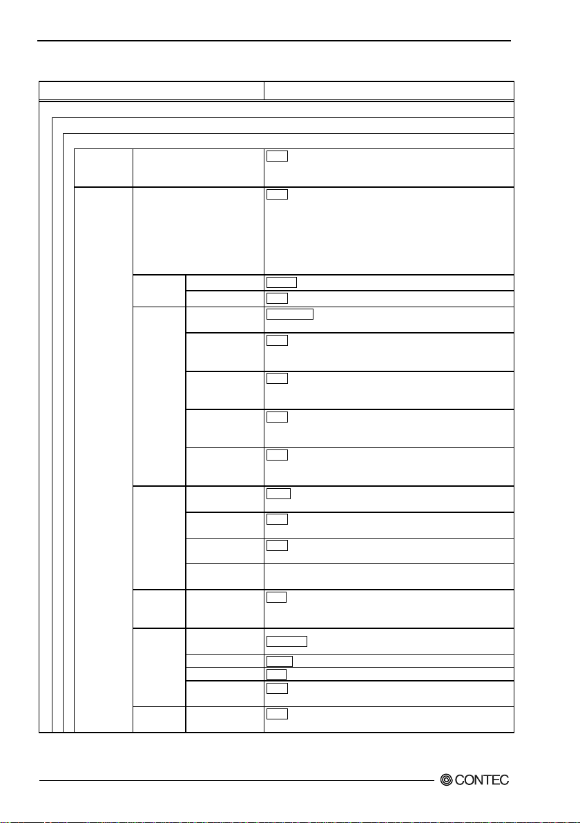
8. Appendix
Basic Settings
VAP Settings
VAP3*22
None , (When set to None, the setting is disabled, between 2 and
only)
None , WEP(Open), WEP(Shared Key), WEP(Auto) * 23, AES,
WPA-AUTO-PSK(AES) *23
Function
Disable, Enable (Type2)
Key
None a 20 digit hexadecimal value (0 to 9, a to f or A to F).
Fixed Ke y 1, Fixed Key 2,
Fixed Key 3, Fixed Key 4,
None , When set to None, the setting is disabled,
hexadecimal value, 152bit:a 32 digit hexadecimal value
None , When set to None, the setting is disabled,
hexadecimal value, 152bit:a 32 digit hexadecimal value
None , When set to None, the setting is disabled,
hexadecimal value, 152bit:a 32 digit hexadecimal value value
None , When set to None, the setting is disabled,
hexadecimal value, 152bit:a 32 digit hexadecimal value
Authentication
Type
PEAP, EAP-TLS
None Up to 32 characters in length, single-byte alphanumeric
characters only, no spaces
None Up to 32 characters in length, single-byte alphanumeric
characters only, no spaces
Certificate
Registration
Server certificate, Client certificate, Private key
WPA setting
(sec)
3600 0(Disable) or 120-259200
Interval (sec)
Server IP Address
0.0.0.0
Server Port
1812
None Up to 64 characters in length, single-byte alphanumeric
characters only
Settings *30
Key (PSK)
None Single-byte alphanumeric characters (from 8 to 63
characters)
Table 8.1 Initial Setting List (4/11)
Item Specification
VAP Settings ESSID
32 characte rs in length, single-byte alphanumeric characters
Encryption
WSL*25
Default key
Fixed Key 1
Key Setting
*26
Encryption
Settings
Supplicant
Settings *27
*28
RADIUS
Server
Settings
*29
PSK
Fixed Key 2
Fixed Key 3
Fixed Key 4
User Name
User Password
Group Key
Updating I nterval
Recertification
Shared Secret
WPA Pre-Shared
IEEE802.1X(WEP)*24, WPA(AES) *24, WPA(TKIP) *24,
WPA-PSK(TKIP), WPA-PSK(AES), WPA2(AES) *24,
WPA2(TKIP) *24, WPA2-PSK(AES),
WPA2-PSK(TKIP),WPA-AUTO(TKIP) *23,
WPA-AUTO(AES) *23, WPA-AUTO-PSK(TKIP) *23,
64bit:a 10 digit hexadecimal value, 128bit:a 26 digit
64bit:a 10 digit hexadecimal value, 128bit:a 26 digit
64bit:a 10 digit hexadecimal value, 128bit:a 26 digit
64bit:a 10 digit hexadecimal value, 128bit:a 26 digit
0(Disable) 0(Disable) or 120-259200
FXA2000-G
84
Page 92

8. Appendix
*22: This setting is available when the unit type is "Access Point" or "Repeater".
*23: This setting is available when the unit type is "Access Point ".
*24: This setting is available when the unit type is "Access Point" or "Station".
*25: This setting is available when the wireless connection mode is "Advanced Infrastructure" or "Standard
Infrastructure".
*26: This setting is available when the encryption is set to either "WEP(Open)", "WEP(SharedKey)", "WEP(Auto)", or
"AES".
*27: This setting is available when the unit type is "Station " and the encryption is set to either "WPA", "WPA2",
"WPA-PSK", or "WPA2-PSK".
*28: This setting is available when the unit type is "Access Point" or " Repeater" and the the encryption is set to either
"WPA", "WPA2", "WPA-PSK", or "WPA2-P SK".
*29: This setting is available when the unit type is "Access Point" and the encryption is set to either "IEEE802.1X",
"WPA", or "WPA2".
*30: This setting is available when the encryption is set to either "WPA-PSK", or "WPA2-PSK".
FXA2000-G
85
Page 93
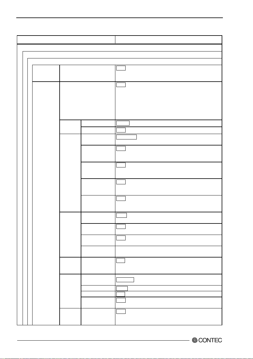
8. Appendix
Basic Settings
VAP Settings
VAP4*31
None , (When set to None, the setting is disabled, between 2
characters only)
None , WEP(Open), WEP(Shared Key), WEP(Auto) * 32, AES,
WPA-AUTO-PSK(AES) *32
Function
Disable, Enable(Type2)
Key
None a 20 digit hexadecimal value (0 to 9, a to f or A to F).
Fixed Ke y 1, Fixed Key 2,
Fixed Key 3, Fixed Key 4,
None , When set to None, the setting is disabled,
hexadecimal value, 152bit:a 32 digit hexadecimal value
None , When set to None, the setting is disabled,
hexadecimal value, 152bit:a 32 digit hexadecimal value
None , When set to None, the setting is disabled,
hexadecimal value, 152bit:a 32 digit hexadecimal value
None , When set to None, the setting is disabled,
hexadecimal value, 152bit:a 32 digit hexadecimal value
Authentication
Type
PEAP, EAP-TLS
None Up to 32 characters in length, single-byte alphanumeric
characters only
None Up to 32 characters in length, single-byte alphanumeric
characters only, no spaces
Certificate
Registration
Server certificate, Client certificate,
Private key
(sec)
3600 0(Disable) or 120-259200
Interval (sec)
Server IP Address
0.0.0.0
Server Port
1812
None Up to 64 characters in length, single-byte alphanumeric
characters only
*39
None Single-byte alphanumeric characters (from 8 to 63
Table 8.1 Initial Set ting List (5/11)
Item Specification
VAP Settings ESSID
and 32 characters in length, single-byte alphanumeric
Encryption
WSL*34
Default key
Fixed Key 1
Key
Setting *35
Encryption
Settings
Supplicant
Settings
*36
WPA
set ting *37
RADIUS
Server
Settings
*38
PSK
Settings
Fixed Key 2
Fixed Key 3
Fixed Key 4
User Name
User Password
Group Key
Updating I nterval
Recertification
Shared Secret
WPA Pre-Shared
Key (PSK)
IEEE802.1X(WEP)*33, WPA(AES) *33, WPA(TKIP) *33,
WPA-PSK(TKIP), WPA-PSK(AES), WPA2(AES) *33,
WPA2(TKIP) *33, WPA2-PSK(AES),
WPA2-PSK(TKIP),WPA-AUTO(TKIP) *32,
WPA-AUTO(AES) *32, WPA-AUTO-PSK(TKIP) *32,
64bit:a 10 digit hexadecimal value, 128bit:a 26 digit
64bit:a 10 digit hexadecimal value, 128bit:a 26 digit
64bit:a 10 digit hexadecimal value, 128bit:a 26 digit
64bit:a 10 digit hexadecimal value, 128bit:a 26 digit
0(Disable) 0(Disable) or 120-259200
characters)
FXA2000-G
86
Page 94

8. Appendix
*31: This setting is available when the unit type is "Access Point" or "Repeater".
*32: This setting is available when the unit type is "Access Point ".
*33: This setting is available when the unit type is "Access Point" or "Station".
*34: This setting is available when the wireless connection mode is "Advanced Infrastructure" or "Standard
Infrastructure".
*35: This setting is available when the encryption is set to either "WEP(Open)", "WEP(SharedKey)", "WEP(Auto)", or
"AES".
*36: This setting is available when the unit type is "Station " and the encryption is set to either "WPA", "WPA2",
"WPA-PSK", or "WPA2-PSK".
*37: This setting is available when the unit type is "Access Point" or " Repeater" and the the encryption is set to either
"WPA", "WPA2", "WPA-PSK", or "WPA2-P SK".
*38: This setting is available when the unit type is "Access Point" and the encryption is set to either "IEEE802.1X",
"WPA", or "WPA2".
*39: This setting is available when the encryption is set to either "WPA-PSK", or "WPA2-PSK".
FXA2000-G
87
Page 95
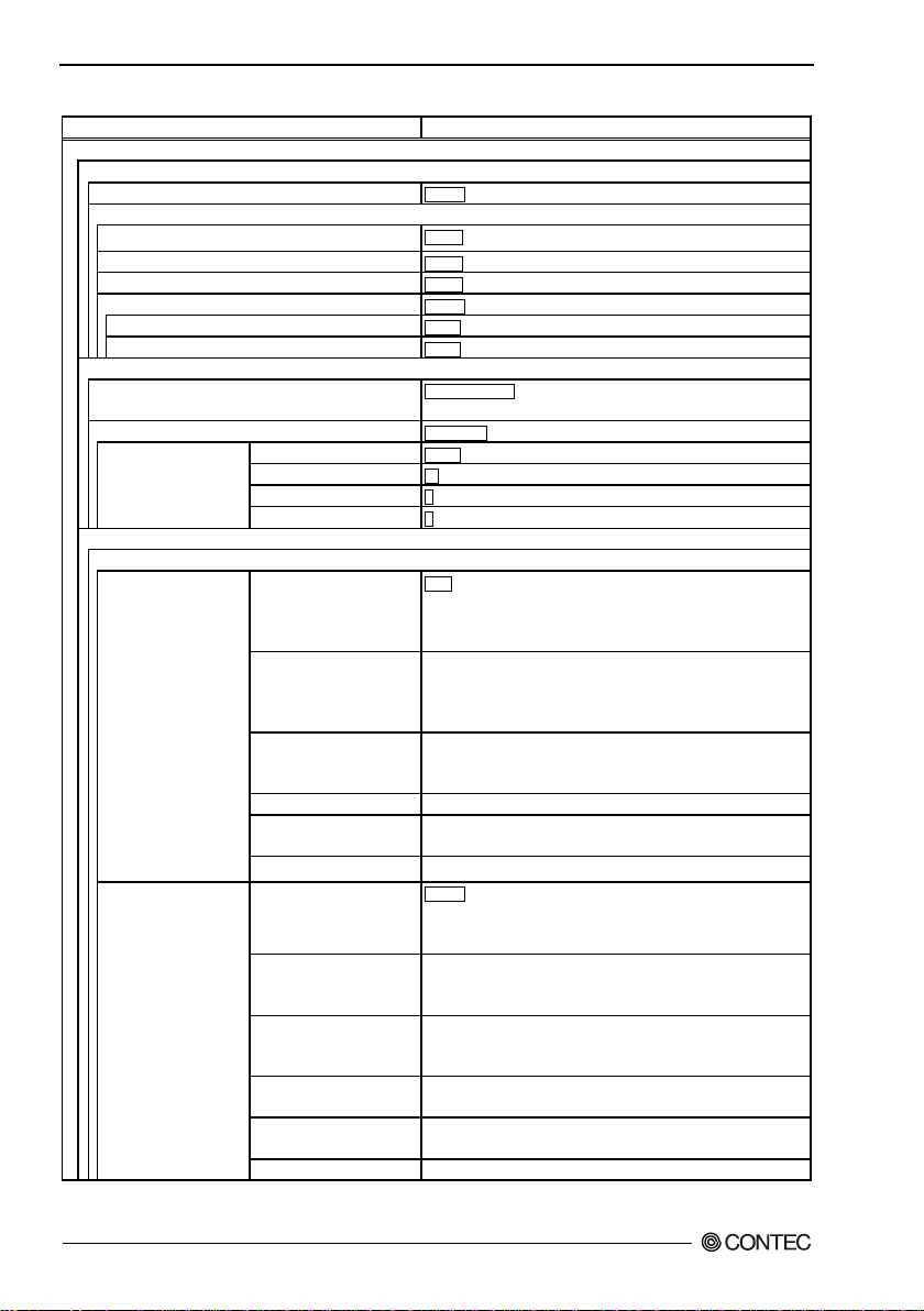
8. Appendix
Item
Specification
Advanced Settings
System HTTPS
Disabl e, Enable
Access S ecuri ty
FTP Server
Enabl e, Disable
Wirel ess Access
Enabl e, Disable
Allowed IP Address Function
Disabl e, Enable
Administrator IP Address 1
0.0.0.0
Administrator IP Address 2
Ethernet
10Mbps(Full-Duple x), 10M bps(Half-Duplex)
Link Down Condition
Link Status, Ping
Ping IP Address
Ping Inte rval (sec)
60 1 - 65 535
Ping Response Wait Time (sec)
3 1 - 15
Ping Retry Co unt
VAP Settings
VAP1
, 1Mbps, 2Mbps, 5.5Mbps, 11Mbps, 6Mbps, 9Mbps, 12Mbps, 18Mbps,
MCS14, MCS15
Auto, 1Mbps, 2Mbps, 5.5Mbps, 11Mbps, 6Mbps, 9Mbps, 12Mbps, 18Mbps,
MCS14, MCS15
54Mbps, MCS0, MCS1, MCS2, MCS3, MCS4, MCS5, MCS6, MCS7, MCS8,
MCS9, MCS10, MCS11, MCS12, MCS13, MCS14, MCS15
IEEE802.11a
Auto, 6Mbps, 9Mbps, 12Mbps, 18Mbps, 24Mbps, 36Mbps, 48Mbps, 54Mbps
Auto, 1Mbps, 2Mbps, 5.5Mbps, 11Mbps, 6Mbps, 9Mbps, 12Mbps, 18Mbps,
24Mbps, 36Mbps, 48Mbps, 54Mbps
MCS13, MCS14, MCS15
MCS12, MCS13, MCS14, MCS15
54Mbps
36Mbps, 48Mbps, 54Mbps
IEEE802.11b
Disable, 1Mbps, 2Mbps, 5.5Mbps, 11Mbps
Table 8.1 Initial Setting List (6/11)
HTTP Server
Port Speed
Ping Parameter
TX Rate
IEEE802.11n (2.4GHz)
Auto*40
IEEE802.11n (5GHz)
IEEE802.11g
IEEE802.11b
IEEE802.11n (2.4GHz)
Auto*40
Enabl e, Disable
0.0.0.0
Auto-Negotiation , 100M(Ful l-Duple x), 100Mbps(Hal f-Duplex),
0.0.0.0
3 0 - 15
Autp
24Mbps, 36Mbps, 48Mbps, 54Mbps, MCS0, MCS1, MCS2, MCS3, MCS4,
MCS5, MCS6, MCS7, MCS8, MCS9, MCS10, MCS11, MCS12, MCS13,
24Mbps, 36Mbps, 48Mbps, 54Mbps, MCS0, MCS1, MCS2, MCS3, MCS4,
MCS5, MCS6, MCS7, MCS8, MCS9, MCS10, MCS11, MCS12, MCS13,
Auto, 6Mbps, 9Mbps, 12Mbps, 18Mbps, 24Mbps, 36Mbps, 48Mbps,
Auto, 1Mbps, 2Mbps, 5.5Mbps, 11Mbps
Disable, 1Mbps, 2Mbps, 5.5Mbps, 11Mbps, 12Mbps, 18Mbps, 24Mbps,
36Mbps, 48Mbps, 54Mbps, MCS1, MCS2, MCS3, MCS4, MCS5, MCS6,
MCS11, MCS1 2, MCS13, MCS14, MCS15
Disable, 1Mbps, 2Mbps, 5.5Mbps, 11Mbps, 12Mbps, 18Mbps, 24Mbps,
36Mbps, 48Mbps, 54Mbps, MCS1, MCS2, MCS3, MCS4, MCS11, MCS12,
Maxi mum TX R ate
*40 : This setting is available when the unit type is "Sta tion".
FXA2000-G
88
IEEE802.11n (5GHz)
IEEE802.11a
IEEE802.11g
Disable, 6Mbps, 9Mbps, 12Mbps, 18Mbps, 24Mbps, 36Mbps, 48Mbps,
54Mbps, MCS0, MCS1, MCS2, MCS3, MCS4, MCS5, MCS6, MCS11,
Disable, 6Mbps, 9Mbps, 12Mbps, 18Mbps, 24Mbps, 36Mbps, 48Mbps,
Disable, 1Mbps, 2Mbps, 5.5Mbps, 11Mbps, 12Mbps, 18Mbps, 24Mbps,
Page 96
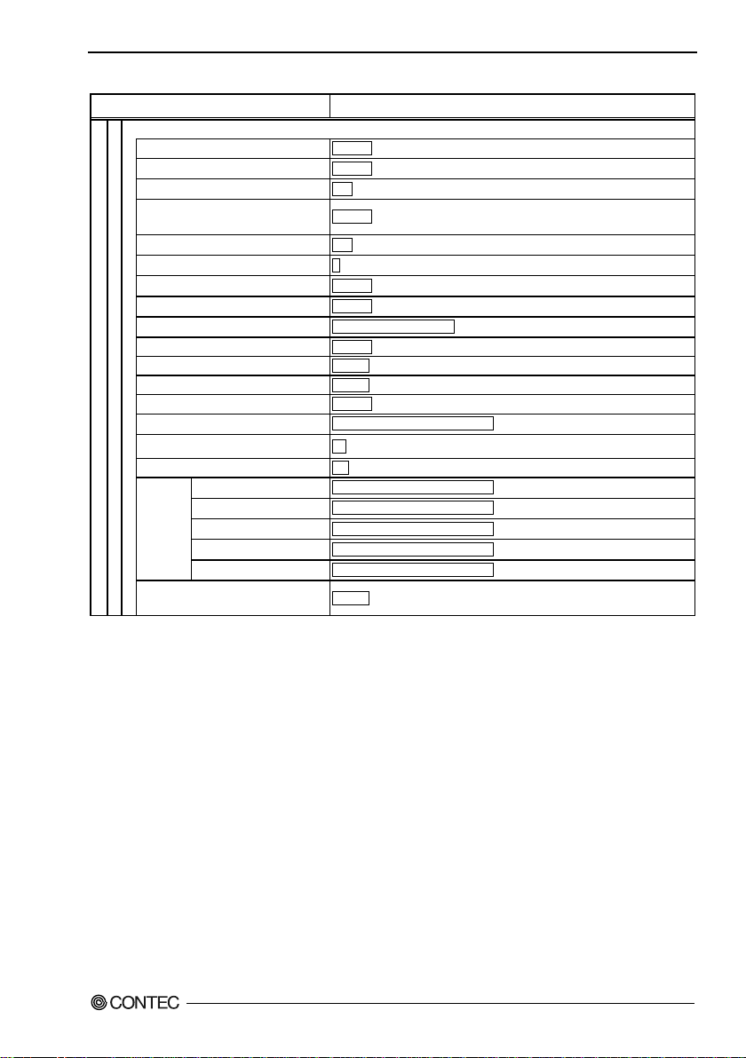
Table 8.1 Initial Setting List (7/11)
VAP1 Link Down Detection
Disable, Enable
ESSID security *41
Disable, Enable
Denial Response (Maximum Client
Beacon Interval (msec) *41
100, 100 - 1000
Disable, RTS-CTS, CTS-only
802.11b(1,2,5.5,11Mbps), 802.11(1,2Mbps)
MAC Address Filtering *41
Disable, [Edit List : Max. 1,024 entries]
WLAN Bridge Between VAP *42
Enable, Disable
WLAN Bridge in This VAP *41
Enable, Disable
Multi-Client *45
Disable, Enable
Static Node Address *46
00-00-00-00-00-00(Not specified), [Specify MAC address of AP]
Scan Channels
All
00-00-00-00-00-00(Not specified) , [Specify MAC address of AP]
Preferred AP 3
00-00-00-00-00-00(Not specified) , [Specify M AC address of AP]
00-00-00-00-00-00(Not specified) , [Specify MAC address of AP]
*47
Item Specification
8. Appendix
Maximum Client Logins *41
Logins) *41
DTIM Period *41
11g Protect Mode
11g Only Mo de *43
Basic Rate *44
Roaming Threshold *47
Preferred AP 1
Preferred
AP *47
Connections to Non-Preferred APs
*41: This setting is available when the unit type is "Access Point" or "Repeater".
*42: This sett ing is available when the unit type is "Access Point".
*43: This setting is available when the unit type is "Access Point" or "Repeater" and the wireless networking standard is
"IEEE 802.11n (2.4GHz)" or "IEEE 802.11g".
*44: This setting is available when the unit type is "Access Point" or "Repeater" and the wireless networking standard is
"IEEE 802.11b", "IEEE 802.11g", or "IEEE 802.11n (2.4GHz)".
*45: This sett ing is available when the unit type is "Station" or "Re peater" and the wireless connection mode is
"Compatible Infrastructure".
*46: This setting is available when the unit type is "Station" or "Repeater", the wireless connection mode is "Compatible
Infrastructure", and the multi-client function is "Disable".
*47: This setting is available when the unit type is "Station" or "Repeater".
Preferred AP 2
Preferred AP 4
Preferred AP 5
128, 1 - 128
Disable, Enable
1, 1 - 15
Disable, Enable
24 0 - 106
00-00-00-00-00-00(Not specified) , [Specify MAC address of AP]
00-00-00-00-00-00(Not specified) , [Specify M AC address of AP]
Enable, Disable
FXA2000-G
89
Page 97
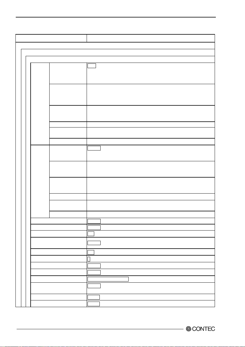
8. Appendix
Advanced Settings
VAP2*3
Auto, 1Mbps, 2Mbps, 5.5Mbps, 11Mbps, 6Mbps, 9Mbps, 12Mbps, 18Mbps,
MCS14, MCS15
Auto, 1Mbps, 2Mbps, 5.5Mbps, 11Mbps, 6Mbps, 9Mbps, 12Mbps, 18Mbps,
MCS14, MCS15
Auto, 6Mbps, 9Mbps, 12Mbps, 18Mbps, 24Mbps, 36Mbps, 48Mbps, 54Mbps,
MCS10, MCS11, MCS12, MCS13, MCS14, MCS15
IEEE802.11a
Auto, 6Mbps, 9Mbps, 12Mbps, 18Mbps, 24Mbps, 36Mbps, 48Mbps, 54Mbps
24Mbps, 36Mbps, 48Mbps, 54Mbps
Disable, 1Mbps, 2Mbps, 5.5Mbps, 11Mbps, 12Mbps, 18Mbps, 24Mbps,
MCS11, MCS12, MCS13, MCS14, MCS15
MCS13, MCS14, MCS15
Disable, 6Mbps, 9Mbps, 12Mbps, 18Mbps, 24Mbps, 36Mbps, 48Mbps,
MCS13, MCS14, MCS15
IEEE802.11a
Disable, 6Mbps, 9Mbps, 12Mbps, 18Mbps, 24Mbps, 36Mbps, 48Mbps, 54Mbps
36Mbps, 48Mbps, 54Mbps
Link Down Detection
Disable, Enable
ESSID security *49
Disable, Enable
Denial Res ponse (Maximum
Beacon Interval (msec) *49
100, 100 - 1000
11g Protect Mode
Disable, [Edit List : Max. 1,024 entries]
WLAN Bridge Between VAP *50
Enable, Disable
Table 8.1 Initial Setting List (8/11)
Item Specification
VAP Settings
TX Rate
Maxi mum
TX Ra te
Maximum Client Logins *49
Client Logins) *49
IEEE802.11n
(2.4GHz)
Auto*48
IEEE802.11n (5GHz)
IEEE802.11g
IEEE802.11b Auto, 1Mbps, 2Mbps, 5.5Mbps, 11Mbps
IEEE802.11n
(2.4GHz)
Auto
IEEE802.11n (5GHz)
IEEE802.11g
IEEE802.11b Disable, 1Mbps, 2Mbps, 5.5Mbps, 11Mbps
24Mbps, 36Mbps, 48Mbps, 54Mbps, MCS0, MCS1, MCS2, MCS3, MCS4,
MCS5, MCS6, MCS7, MCS8, MCS9, MCS10, MCS11, MCS12, MCS13,
24Mbps, 36Mbps, 48Mbps, 54Mbps, MCS0, MCS1, MCS2, MCS3, MCS4,
MCS5, MCS6, MCS7, MCS8, MCS9, MCS10, MCS11, MCS12, MCS13,
MCS0, MCS1, MCS2, MCS3, MCS4, MCS5, MCS6, MCS7, MCS8, MCS9,
Auto, 1Mbps, 2Mbps, 5.5Mbps, 11Mbps, 6Mbps, 9Mbps, 12Mbps, 18Mbps,
36Mbps, 48Mbps, 54Mbps, MCS1, MCS2, MCS3, MCS4, MCS5, MCS6,
Disable, 1Mbps, 2Mbps, 5.5Mbps, 11Mbps, 12Mbps, 18Mbps, 24Mbps,
36Mbps, 48Mbps, 54Mbps, MCS1, MCS2, MCS3, MCS4, MCS11, MCS12,
54Mbps, MCS0, MCS1, MCS2, MCS3, MCS4, MCS5, MCS6, MCS11, MCS12,
Disable, 1Mbps, 2Mbps, 5.5Mbps, 11Mbps, 12Mbps, 18Mbps, 24Mbps,
128, 1 - 128
Disable, Enable
DTIM Period *49 1 , 1 - 15
Disable , RTS-CTS, CTS-only
11g Only Mo de *51 Disable, Enable
Basic Rate *52 802.11b (1,2,5.5,11Mbps), 802.11(1,2Mbps)
MAC Address Filtering *49
WLAN Bridge in This VAP *49
FXA2000-G
90
Enable, Disable
Page 98

8. Appendix
*48: This setting can be configured "Repeater" or "Access Point ".
*49: This setting is available when the unit type is "Access Point" or "Repeater".
*50: This setting is available when the unit type is "Access Point ".
*51: This setting is available when the unit type is "Access Point" or "Repeater" and the wireless networking standard is
"IEEE 802.11n (2.4GHz)" or "IEEE 802.11g".
*52: This setting is available when the unit type is "Access Point" or "Repeater" and the wireless networking standard is
"IEEE 802.11b", "IEEE 802.11g", or "IEEE 802.11n (2.4GHz)".
FXA2000-G
91
Page 99
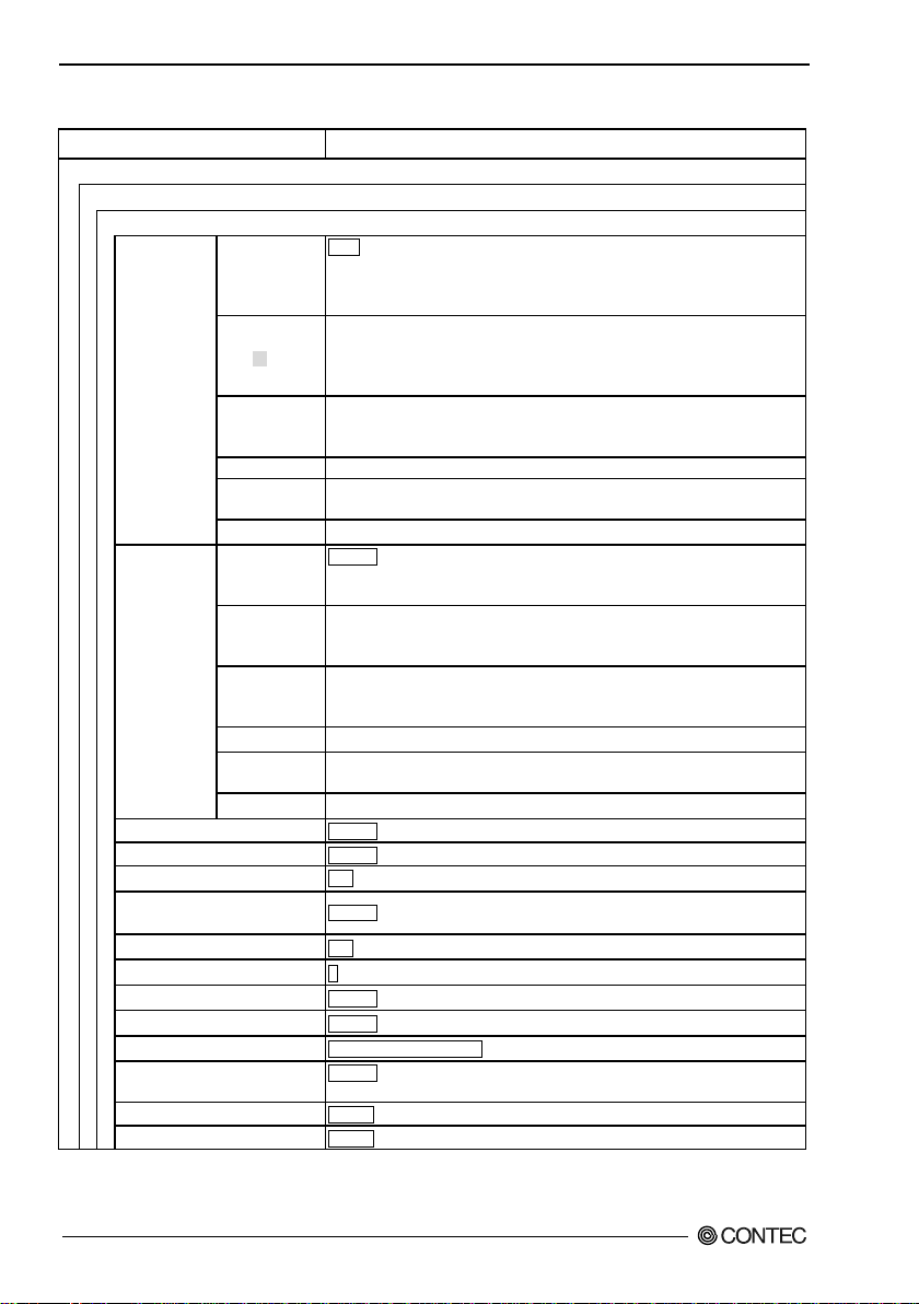
8. Appendix
Advanced Settings
VAP3*3
Auto, 1Mbps, 2Mbps, 5.5Mbps, 11Mbps, 6Mbps, 9Mbps, 12Mbps, 18Mbps,
MCS14, MCS15
Auto, 1Mbps, 2Mbps, 5.5Mbps, 11Mbps, 6Mbps, 9Mbps, 12Mbps, 18Mbps,
MCS14, MCS15
Auto, 6Mbps, 9Mbps, 12Mbps, 18Mbps, 24Mbps, 36Mbps, 48Mbps, 54Mbps,
MCS10, MCS11, MCS12, MCS13, MCS14, MCS15
IEEE802.11a
Auto, 6Mbps, 9Mbps, 12Mbps, 18Mbps, 24Mbps, 36Mbps, 48Mbps, 54Mbps
24Mbps, 36Mbps, 48Mbps, 54Mbps
Disable, 1Mbps, 2Mbps, 5.5Mbps, 11Mbps, 12Mbps, 18Mbps, 24Mbps,
MCS11, MCS12, MCS13, MCS14, MCS15
MCS13, MCS14, MCS15
Disable, 6Mbps, 9Mbps, 12Mbps, 18Mbps, 24Mbps, 36Mbps, 48Mbps,
MCS13, MCS14, MCS15
IEEE802.11a
Disable, 6Mbps, 9Mbps, 12Mbps, 18Mbps, 24Mbps, 36Mbps, 48Mbps, 54Mbps
36Mbps, 48Mbps, 54Mbps
Link Down Detection
Disable, Enable
ESSID security *54
Disable, Enable
Denial Res ponse (Maximum
Beacon Interval (msec) *54
100, 100 - 1000
11g Protect Mode
Disable , [Edit List : Max. 1,024 entries]
WLAN Bridge Between VAP *55
Enable, Disable
WLAN Bridge in This VAP *54
Enable, Disable
Table 8.1 Initial Setting List (9/11)
Item Specification
VAP Settings
TX Rate
Maxi mum TX
Rate
Maximum Client Logins *54
Client Logins) *54
IEEE802.11n
(2.4GHz)
Auto *2
IEEE802.11n
(5GHz)
IEEE802.11g
IEEE802.11b Auto, 1Mbps, 2Mbps, 5.5Mbps, 11Mbps
IEEE802.11n
(2.4GHz)
Auto
IEEE802.11n
(5GHz)
IEEE802.11g
IEEE802.11b Disable, 1Mbps, 2Mbps, 5.5Mbps, 11Mbps
24Mbps, 36Mbps, 48Mbps, 54Mbps, MCS0, MCS1, MCS2, MCS3, MCS4,
MCS5, MCS6, MCS7, MCS8, MCS9, MCS10, MCS11, MCS12, MCS13,
24Mbps, 36Mbps, 48Mbps, 54Mbps, MCS0, MCS1, MCS2, MCS3, MCS4,
MCS5, MCS6, MCS7, MCS8, MCS9, MCS10, MCS11, MCS12, MCS13,
MCS0, MCS1, MCS2, MCS3, MCS4, MCS5, MCS6, MCS7, MCS8, MCS9,
Auto, 1Mbps, 2Mbps, 5.5Mbps, 11Mbps, 6Mbps, 9Mbps, 12Mbps, 18Mbps,
36Mbps, 48Mbps, 54Mbps, MCS1, MCS2, MCS3, MCS4, MCS5, MCS6,
Disable, 1Mbps, 2Mbps, 5.5Mbps, 11Mbps, 12Mbps, 18Mbps, 24Mbps,
36Mbps, 48Mbps, 54Mbps, MCS1, MCS2, MCS3, MCS4, MCS11, MCS12,
54Mbps, MCS0, MCS1, MCS2, MCS3, MCS4, MCS5, MCS6, MCS11, MCS12,
Disable, 1Mbps, 2Mbps, 5.5Mbps, 11Mbps, 12Mbps, 18Mbps, 24Mbps,
128, 1 - 128
Disable, Enable
DTIM Period *54 1 , 1 - 15
Disable, RTS-CTS, CTS-only
11g Only Mo de *56 Disable, Enable
Basic Rate *57 802.11b (1,2,5.5,11Mbps), 802.11(1,2Mbps)
MAC Address Filtering *54
FXA2000-G
92
Page 100

8. Appendix
*54: This setting is available when the unit type is "Access Point" or "Repeater".
*55: This setting is available when the unit type is "Access Point ".
*56: This setting is available when the unit type is "Access Point" or "Repeater" and the wireless networking standard is
"IEEE 802.11n (2.4GHz)" or "IEEE 802.11g".
*57: This setting is available when the unit type is "Access Point" or "Repeater" and the wireless networking standard is
"IEEE 802.11b", "IEEE 802.11g", or "IEEE 802.11n (2.4GHz)".
FXA2000-G
93
 Loading...