


 Loading...
User Manual
For all model numbers – except wireless.
FlexAray75 is intended for professional use. Read the User Manual in its entirety before operating the product.
Copyright 2012, 0energyLIGHTING, LLC.
All Rights Reserved
Product specifications and information are subject to change without notice.
Contents |
|
General Information................................................................................................................................................................................. |
4 |
Safety Warnings ................................................................................................................................................................................... |
4 |
RISK OF ELECTRICAL SHOCK ............................................................................................................................................................... |
4 |
SAFETY GUIDELINES............................................................................................................................................................................... |
4 |
Technical and Warranty Assistance ................................................................................................................................................. |
4 |
Maintenance........................................................................................................................................................................................ |
4 |
Specifications ............................................................................................................................................................................................ |
5 |
Description............................................................................................................................................................................................ |
5 |
Characteristics........................................................................................................................................................................................... |
5 |
Physical.................................................................................................................................................................................................. |
5 |
Electrical................................................................................................................................................................................................ |
5 |
LED Emitters........................................................................................................................................................................................... |
5 |
Controls ................................................................................................................................................................................................. |
5 |
Operating Modes ................................................................................................................................................................................ |
5 |
Agency and Environmental Compliance ....................................................................................................................................... |
6 |
Electrical..................................................................................................................................................................................................... |
7 |
Installation ............................................................................................................................................................................................. |
7 |
Molded Power Cord (included in the box) ..................................................................................................................................... |
7 |
36-inch US Power Cord .................................................................................................................................................................. |
7 |
Accessories ........................................................................................................................................................................................... |
7 |
Interconnection Cords (FA-PWR9 and FA-PWR36)......................................................................................................................... |
7 |
9 and 36-inch Power Connectors ................................................................................................................................................ |
7 |
Universal Power Cord (FA-PWR) ........................................................................................................................................................ |
7 |
36-inch Universal Power Cord....................................................................................................................................................... |
7 |
DMX XLR Connections (provided by others)................................................................................................................................... |
8 |
Mechanical and Interconnection ......................................................................................................................................................... |
9 |
Mechanical Limitations....................................................................................................................................................................... |
9 |
Secondary Safety Cable .................................................................................................................................................................. |
10 |
Hardware Accessories ...................................................................................................................................................................... |
11 |
Hanger Blocks (FA-BMSK-x-2) ........................................................................................................................................................... |
11 |
Yoke (FA-Y-x-1) ................................................................................................................................................................................... |
12 |
Single-arm Hangers (FA-SH-x-1) ....................................................................................................................................................... |
13 |
Extension Hangers (FA-EXT-x-2) ........................................................................................................................................................ |
14 |
Interlock Device (FA-INT-x-1)............................................................................................................................................................ |
15 |
Optical Accessories (FA-OPTx-1) ..................................................................................................................................................... |
16 |
Accessory Installation........................................................................................................................................................................ |
17 |
Digital Panel Controls – User Interface ................................................................................................................................................ |
18 |
Digital Display ..................................................................................................................................................................................... |
18 |
Buttons ................................................................................................................................................................................................. |
18 |
FlexAray™ Manual |
|
www.0energyLIGHTING.com |
page 2 |
LED Indicators..................................................................................................................................................................................... |
18 |
Programming Modes and Settings....................................................................................................................................................... |
19 |
Control Modes.................................................................................................................................................................................... |
19 |
Mode Settings..................................................................................................................................................................................... |
19 |
DMX Mode.......................................................................................................................................................................................... |
19 |
Stand-alone Mode ............................................................................................................................................................................ |
19 |
Table 1: Stand-alone Values ....................................................................................................................................................... |
19 |
Table 2: Fade Pattern Values (101-140)..................................................................................................................................... |
20 |
Table 1: Master Values................................................................................................................................................................. |
21 |
Table 2: Fade Pattern Values (101-140)..................................................................................................................................... |
22 |
Table 3: Self-Test Mode ................................................................................................................................................................ |
23 |
Warranty Statement ............................................................................................................................................................................... |
24 |
Flow Chart – RGBaW – model FA75-C................................................................................................................................................. |
26 |
Flow Chart –Vari White – model FA75-V.............................................................................................................................................. |
30 |
Flow Chart – S32, S44 and or S56 – models FA75-S32, FA75-S44, FA75-S56..................................................................................... |
34 |
FlexAray™ Manual
www.0energyLIGHTING.com page 3

General Information
Safety Warnings
 WARNING! Read all instructions and warnings in the enclosed instructional brochure before assembling, mounting, installing or operating this FlexAray™ fixture or accessory. Failure to read, thoroughly understand, and follow all instructions and warnings can result in personal injury, damage to equipment, or voiding of warranty. This FlexAray™ fixture or accessory is potentially hazardous if not properly mounted, properly used with, or properly joined with additional FlexAray™ fixtures or accessories. KEEP INSTRUCTIONS FOR FUTURE USE. DO NOT USE THIS FIXTURE IF NOT PROPERLY MOUNTED!
FlexAray™ is intended for professional use. Read the User Manual in its entirety before operating the product.
RISK OF ELECTRICAL SHOCK
FlexAray™ is a lighting product powered by sufficient electricity to cause harm to the human body. Use care and caution when handling and powering the product to avoid direct contact with electrical sources.
SAFETY GUIDELINES
Do not position or mount the product near open flames.
Use FlexAray™ in dry and damp locations only. The fixtures are not intended for wet applications.
Use only FlexAray™ mounting accessories to suspend the fixtures, and use them as instructed herein.
Disconnect power and DMX sources before performing any maintenance on the fixtures.
Use an approved safety cable as a supplemental restraint on every fixture. Do not rely solely on the FlexAray™
mounting accessories.
Technical and Warranty Assistance
If you have questions about the FlexAray™ series of fixtures that are not answered in this manual, or require warranty assistance, contact the local supplier of your FlexAray™ equipment or 0energyLIGHTING Technical Support, or visit the FlexAray™ website.
0energyLIGHTING, LLC
424 East Central Boulevard Suite 192 Orlando FL 32801
support@flexaray.com
+1 888-647-2852 www.FlexAray.com
Maintenance
Before conducting any maintenance operations unplug the fixture and allow it to cool to room temperature. Never spray anything onto a hot fixture. DO NOT spray anything into the fixture except compressed air that is filtered for moisture removal first, and only when the fixture is cool.
At least once per year, clean the room-temperature fixture by wiping down the external faces with an electrically-safe cleaning or lint-free dry cloth. To clear settled dust, blow clean dry air into the fixture from front to back. Then blow the fan housing on the back free of any remaining dust. Operate the fixture in self-test mode (see instructions below) to verify function of each output channel.
Inspect the fixture, accessories, and mounting devices for wear and tear, and replace any parts that appear damaged or excessively worn.
FlexAray™ Manual
www.0energyLIGHTING.com page 4
Specifications
Description
FlexAray™ is a stage and studio luminaire with features proprietary to its manufacturer, 0energyLIGHTING, LLC. FlexAray™ products are manufactured by 0energyLIGHTING.
FlexAray™ products include a number of proprietary features including (1) the mechanical design of the fixture providing a unique method of interconnection with additional units, (2) controls that offer multiple DMX resolutions, (3) controls that provide for individual, repeatable customization, (4) FlexPalette™ controls that provide for user recorded color palette(s), and (5) FlexRate™ controls that provide for user-controlled frequency rating.
Characteristics
Physical
The fixtures are hexagonal along the axis in which they point, with slots on each face of the hexagon providing for the use of interlocking devices.
FlexAray™ FA-75 which is 7.5-inches in diameter, and 10.5-inches in length, and weighing less than 10 lbs., not including mounting hardware. Additional models are under development.
Fixtures are made and tested for damp location approvals, consistent with an IP20 rating. The fixtures are formed of rugged metals and plastics, properly cleaned and free of defects, and finished to industry standards for both aesthetic and protective purposes.
The FlexAray™ power supply, cooling system and electronics are integral to each fixture. Each physical unit consists of at least (1) a hexagonal fixture, (2) a 3-foot power lead, and (3) a safety cable intended for use with the unit to prevent falls.
Optional standard accessories include hanging brackets of different configurations with holes for ½-inch thru-hole fasteners, optical diffusers, physical interconnection devices, electrical interconnection devices, and wireless DMX reception.
Electrical
The fixture operates on non-dimmed line voltage with a minimum input range of 100 to 240vAC at 50 to 60hz. The fixture and power accessories utilize Neutrik® PowerCon™ power connectors or approved equals. Each unit includes both an input and an output connector for daisy-chained power connections.
Each unit includes limited internal protection against over-voltage, over-current, heat, and open and shorted circuits. Fixture power supplies include energy-star ratings where possible and applicable, and are NRTL recognized for inclusion in the fixture.
LED Emitters
Based on the model number, FlexAray™ fixtures employ a combination of red, green, blue, amber and white light emitting diodes for broad output options. All LEDs are high-power emitters of proven quality from established, reputable and industry-leading LED manufacturers. LEDs are manufactured to specification of an advanced binning process for color consistency. Employed LEDs have an expected and manufacturer-rated nominal life of at least 50,000 hours. All LED subassemblies are subjected to a 4-hour burn-in test during production.
Controls
The fixture complies with the USITT DMX512 standards of 1990 and forward. Multiple DMX modes are offered including both 8 and 16-bit inputs. 16-bit modes utilize two consecutive addresses per output channel.
Operating Modes
FlexAray™ fixtures incorporate the following DMX modes:
DMX Mode 1 offers an 8-bit input resolution with 10-bit output resolution at any of four user-selectable high frequencies for flicker free operation.
FlexAray™ Manual
www.0energyLIGHTING.com page 5
DMX Mode 2 offers an 8-bit input resolution with 10-bit output resolution at any of four user-selectable high frequencies for flicker free operation. The last channel is a master intensity control of all other output channels. This channel includes a user-selectable choice of standard or inverted control.
DMX Mode 3 offers a 16-bit input resolution with 16-bit output resolution at any of four user-selectable high frequencies for flicker free operation.
DMX Mode 4 offers a 16-bit input resolution with 16-bit output resolution at any of four user-selectable high frequencies for flicker free operation. The last two channels are a master intensity control (course and fine) of all other output channels. These channels include a user-selectable choice of standard or inverted control.
Wireless DMX reception is optional and accomplished with the inclusion of an internal LumenRadio™ DMX receiver and externally mounted antenna. All DMX modes and options are available in wireless operation. One LumenRadio™ wireless DMX unit can receive and broadcast a DMX signal to multiple down-steam units connected via XLR.
The fixture offers stand-alone operation with user-programmable features of 100 user-programmable color memory locations and 80 user-selectable combinations of fade and/or bump timing.
The fixture offers a user-selectable feature to create master/slave relationships based on down-stream XLR connections. Master mode distributes any Stand-alone output to downstream fixtures. Incoming XLR and wireless DMX inputs are disabled in this unit when in Master mode. Downstream slave fixtures react to the Stand-alone Master instructions in synchronous operation with the master. Any downstream XLR connected unit set to Master mode begins a new control string of further downstream units.
The fixture offers a user-selectable option to set and terminate the XLR string it ends. No external termination device is required.
The fixture’s controls include a self-test mode of two steps. Step 1 quickly tests and transitions through colors and fading, while Step 2 then repeats a simple output pattern for continuous testing or demonstration.
Emitter output is flicker-free and includes a selection of four output frequencies for each of the four DMX modes. PWM control of LED levels is imperceptible to video cameras and similar equipment.
Agency and Environmental Compliance
FlexAray™ fixtures are RoHS compliant and NRTL listed to the UL 1573 and 8750 standard(s).
FlexAray™ Manual
www.0energyLIGHTING.com page 6
Electrical
Installation
FlexAray™ fixtures operate on 100 to 240vAC at 50 to 60 Hertz. A risk of electrical shock exists. Each fixture contains one input and one output power connection jack.
Do not operate the FlexAray™ fixture on a dimmed circuit. The fixture requires constant input voltage.
Molded Power Cord (included in the box)
Primary power cord to Edison cord cap for use to feed primary power to one or multiple interconnected units.
36-inch US Power Cord
A 36-inch US Power Cord is included with your fixture. This cord includes a Neutrik powerCON cord cap on one end and an Edison 3-prong cord cap on the other.
To use this cord, simply insert the Neutrik powerCON cord cap into the matching color socket on a fixture and twist the connector clockwise until it locks. Connect the opposite end to primary power.
To disconnect a Neutrik powerCON from its socket, pull the metal locking tab on the cord cap back while turning the cord cap counterclockwise and out of the socket.
You can connect up to 10 fixtures in a daisy-chain. DO NOT exceed 10 fixtures per power cord.
Accessories
The following electrical accessories are available for the FlexAray™ fixture.
9-inch fixture-to-fixture Power Connector (FA-PWR9)
36-inch fixture-to-fixture Power Connector (FA-PWR36)
36-inch Universal Replacement Power Cord (FA-PWR)
Interconnection Cords (FA-PWR9 and FA-PWR36)
These power cords are used to interconnect multiple units.
9 and 36-inch Power Connectors
Power Connectors are interconnecting cables to make power feeds from one fixture to another as a daisy chain. Power Connectors are sold separately and available in both 9 and 36-inch lengths. Each connector includes an installed pair of Neutrik powerCON cord caps that differ by color and locking tab. With this configuration, the color coding allows you to match the powerCON colors on both the fixture and the connector (blue to blue, gray to gray) to make proper power connections.
To use the Power Connectors, simply insert the cord cap on one end into the matching color socket on a fixture and twist the connector clockwise until it locks. Insert the opposite end’s cord cap into a matching color socket on another fixture and twist the connector clockwise until it locks. Power and grounding is now supplied through the first fixture to the second, and so on.
To disconnect a Neutrik powerCON from its socket, pull the metal locking tab on the cord cap back while turning the cord cap counterclockwise and then out of the socket.
You can connect up to 10 fixtures in a daisy-chain. DO NOT exceed 10 fixtures per primary power cord.
Universal Power Cord (FA-PWR)
Primary power cord to bare end for use to feed primary power to one or multiple interconnected units, a separately purchased cord cap will need to be bought and installed properly.
36-inch Universal Power Cord
The 36-inch Universal Power Cord is sold separately as a replacement power supply cable when Edison cord caps are not required. The Universal Power Cord includes a Neutrik powerCON cord cap on one end and is bare ended on the other, allowing you to have your choice of primary power cord caps to be installed.
|
To use the Universal Power Cord once you have had the required cord cap installed, simply insert the Neutrik |
|
powerCON cord cap into the matching color socket on a fixture and twist the connector clockwise until it locks. |
|
|
Connect the opposite end to the primary power. |
|
|
FlexAray™ Manual |
page 7 |
|
www.0energyLIGHTING.com |
||
To disconnect a Neutrik powerCON from its socket, pull the metal locking tab on the cord cap back while turning the cord cap counterclockwise and then out of the socket.
You can connect up to 10 fixtures in a daisy-chain. DO NOT exceed 10 fixtures per power cord.
DMX XLR Connections (provided by others)
Each FlexAray™ fixture includes one male and one female 5-pin XLR connector for the DMX signal. Incoming DMX should be connected to the male XLR connector and outgoing to the female. This is critical in wireless and master mode applications where only the female conveys the DMX signal to subsequent fixtures.
FlexAray™ Manual
www.0energyLIGHTING.com page 8

Mechanical and Interconnection
The primary goal of the FlexAray™ mechanical design is to offer users a wide variety of options for deployment of the fixtures. These options all surround two basic, proprietary characteristics of the fixture design – the hexagonal shape and the interlock feature. Options for use are further expanded via the various mounting hardware options.
Mechanical Limitations
Proper use of the FlexAray™ fixture and accessories are constrained by the following mechanical and electrical limitations, as tested and certified by the NRTL and as labeled on the fixture:
Always install at least one secondary safety cable on each fixture and connect to a secure hanging structure that does not include a hanger or FlexAray™ accessory.
No more than ten (10) FA75 fixtures may be hung from one hanger setup. Each such hanger setup consists of either one yoke (FA75-Y-x-1) AND a set of two hanger blocks (FA-BMSK-x-2) and/or a set of two single hanger brackets (FA-SH-x-2) AND a set of two hanger blocks (FA-BMSK-x-2).
No more than ten (10) FA75 fixtures may be powered by a common power feed (power cord).
Remember, a proper hanger setup has two connection points to the interlocked fixtures.
When interlocking assemblies are used on a surface and not hung, the mechanical possibilities are virtually unlimited. HOWEVER, no more than ten (10) FA75 fixtures may be powered by a common power feed (power cord).
DO NOT use a tool or device other than your hand to tighten the grip-handle nuts of the hanger block assemblies, as this may damage the nut.
 WARNING! Read all instructions and warnings in the downloadable instructional brochure before assembling, mounting, installing or operating this FlexAray™ fixture or accessory. Failures to read, thoroughly understand, and follow all instructions and warnings can result in personal injury, damage to equipment, or voiding of warranty.
This FlexAray™ fixture or accessory is potentially hazardous if not properly mounted, properly used with, or properly joined with additional FlexAray™ fixtures or accessories.
KEEP INSTRUCTIONS FOR FUTURE USE.
DO NOT USE THIS FIXTURE IF NOT PROPERLY MOUNTED!
FlexAray™ Manual
www.0energyLIGHTING.com page 9
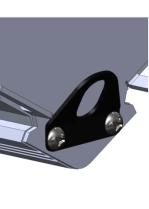
Secondary Safety Cable
A 36-inch secondary safety cable; (made by others), is included with each fixture. This cable includes a loop at one end and a carabineer on the other. Attach the cable securely to the fixture and the hanging structure by choking through the enclosed loop and clipping the carabineer to the other, or choking both ends.
Always install at least one secondary safety cable on each fixture and connect to a secure hanging structure that does not include a hanger clamp or FlexAray™ accessory.
The below image is the clip on the unit that the safety cable connects through.
FlexAray™ Manual
www.0energyLIGHTING.com page 10
Hardware Accessories
Your FlexAray™ fixture can be used with a variety of FlexAray™ accessories. These accessories include the following list and are sold separately. Instructions for use of each accessory provided below.
Hanger Blocks (FA-BMSK-x-2)
Yoke (FA75-Y-B-1)
Single-arm Hangers (FA-SH-x-2)
Extension Hangers (FA-EXT-x-2)
Interlock Device (FA75-INT-x-2)
Hanger Blocks (FA-BMSK-x-2)
Each FA-BMSK hanger block kit consists of a set of two hanger pads plus all hardware for their use. Hanger Blocks are sold separately as a set of two and should always be used in pairs.
Generally, installing the hanger block onto the FA75 fixture consists of the following:
Insert an included ½-in bolt through the hole in a hanger pad with the head of the bolt recessed into the cavity on one side of the pad.
Place the included internal-tooth washer onto the bolt.
Put the bolt through the appropriate mounting hole in an accessory or environment.
Install the grip-handle nut onto the bolt and hand-tighten.
Slide the assembled hanger block into a slot on one of the six fixture sides. Note the position of the block relative to the front of the unit and possible front accessory usage.
Using a 1/8-inch Allen wrench (included), tighten the set screws (2) in the hanger pad against the fixture body so that the pad no longer slides. A force of at least 7 to 10 pounds is all that is needed to secure the pad in place. Test to see that the pad does not slide once secured.
Install a Safety Ring on the bent tab at the back end of the slot where the hanger pad is installed.
Repeat this process for the opposite side of the fixture or group of fixtures, aligning the second pad directly across from the first.
FlexAray™ Manual
www.0energyLIGHTING.com page 11

Yoke (FA-Y-x-1)
The yoke hanger fits from side-to-side on any FA75 FlexAray™ fixture and attaches with a set of hanger blocks. When using a yoke, fully assemble the hanger setup before installing the setup onto the fixture. Otherwise, you will find it nearly impossible to stretch the yoke over the hanger blocks’ mounting bolts and may cause damage to the yoke.
To assemble this setup:
Insert an included ½-in bolt through the hole in a hanger pad with the head of the bolt recessed into the cavity on one side of the pad.
Place the included internal-tooth washer onto the bolt.
Put the bolt through the hole in the yoke.
Install the grip-handle nut onto the bolt and hand-tighten.
Repeat this process for the other side of the yoke.
Slide the yoke assembly into opposing slots on the fixture sides. Note the position of the yoke relative to the front of the unit and possible front accessory usage.
Install a Safety Ring on each of the bent tabs at the back end of the slots where the hanger pad is installed.
Using a 1/8-inch Allen wrench (included), tighten the set screws (2) in each hanger pad against the fixture body
so that the pad no longer slides. A force of about 7 to 10 pounds is all that is needed to secure the pad in place. Test to
see that the pad does not slide once secured.
THE FINAL STEP IS TO INSERT THE PROVIDED CARABINEER INTO THE INTERLOCK SLOT TO PREVENT THE HANGER PAD FROM ACCIDENTALLY FALLING OUT.
FlexAray™ Manual
www.0energyLIGHTING.com page 12
Loading...