

Page 1
Monster Fan M350
Class V-VIII*
SINGLE UNIT: For vehicles with engines up to 335 hp and at least 1,200 square inches of clear radiator core area.
DOUBLE UNITS: For vehicles with engines of 335-400 hp and at least 1,400 square inches of clear radiator core
area.
Caution:
adequate alternator capacity before installing dual M350 units.
* The Black Magic M350 may be used in smaller class trucks when there is adequate clearance for installation.
IMPORT ANT NOTE:
Please read instructions completely before attempting installation. We recommend a thorough inspection of your radiator for any visual
defects (such as cracks or breaks in the side rails, radiator core or tank leaks) before continuing. The M350 is designed for installation on a
properly functioning cooling system and is not a substitute for regular system maintenance.
The M350 is packaged as a working unit. It is designed to function in a SUCKER MODE ONLY and should always be mounted on the
ENGINE SIDE of the radiator so that the fan faces the engine block.
REMOVE EXISTING FAN & SHROUD ASSEMBLY:
1. Remove plastic radiator cover, and top half of fan shroud (some shrouds are a single piece).
2. Remove fan and clutch assembly. If clutch is mounted to pulley with four bolts, remove nuts, remove clutch/fan assembly and replace nuts.
The clutch may be mounted by a large single nut. It may be possible to remove this clutch by fitting a large wrench to the nut. Put a rag over
the fan to keep from being cut. Hold the fan in place and pull the wrench in the direction of rotation, it may help to give the end of the
wrench a sharp strike from a soft-blow hammer to break the nut free without the pulley slipping.
3. Remove the lower shroud.
Dual M350s in simultaneous operation will draw up to 100 amp s. Vehicle operator must insure
INSTALLATION INSTRUCTIONS
WIRE FAN MOTORS:
1. Each motor has two wires, one black the other blue. For this application the Black motor wire is Positive, and the Blue motor wire is
Negative. Locate the rolls of 10 GA red and black wire, and the yellow butt connectors. Attach the red 10 GA wires to the Black motor wires.
And the black 10 GA wires to the Blue motor wires. Now the red 10 GA wire will be positive (+) and the black 10 GA wire will be Negative
(-).
2. Wrap the connections with electrical tape, and use ‘zip-ties’ to
secure the wires away from the rotating fan blades.
3. Drill a small hole in the shroud to pass the 10 GA wires through to
the outside of the shroud.
INSTALL ELECTRIC FAN ASSEMBL Y :
1. Look at the vehicle construction around the radiator for potential
mounting points. Mounting points should serve two purposes:
to carry the weight of the fan, and to hold the fan against the
radiator core. Cross braces, radiator mounting points, radiator
flanges, or side rails are possible points. Locate at least 4 points
to mount bracket to.
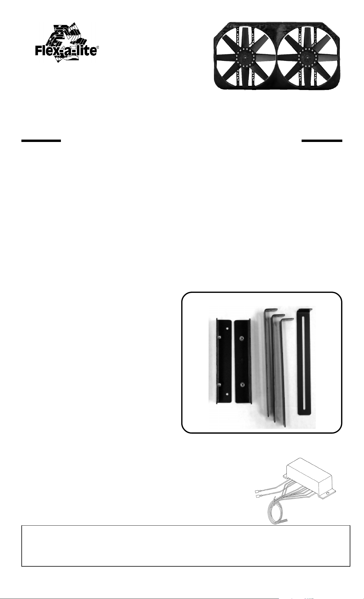
2. There are two different styles of brackets, and four mounting
straps included in the kit. (Diagram 1) These can be used to give
you the most options for mounting the fan to the radiator. The
mounting straps can be bent to reach around the radiator if
necessary. The long slot in the straps allows adjustment to the
tension of the fan mount against the radiator core.
3. We do not recommend mounting the brackets to the radiator core
so that the core carries the weight of the fan. In some applications this can cause damage to the core.
BRACKETS PROVIDED: (Diagram 1)
MOUNTING CONTROL MODULE:
1. A remote mounted control module is shipped with each M350.
A drawing of the control is shown as Diagram 2
2. Select a point near the fan where the control can be mounted. The unit is sealed so it can be mounted in the engine bay, but should be
protected from extreme heat. The firewall is a common mounting point. Using the control as a template,
mark hole locations and drill 1/8” holes.
CAUTION- Be sure it is safe to drill at this position and that nothing is behind this location.
3. Mount the control with the wires hanging down, so not to trap moisture.
Diagram 2
CONTINUE TO BACK SIDE TO COMPLETE THE INSTALLATION.
The Flex-a-lite Limited Warranty
Flex-a-lite Consolidated, 7213-45th St. Ct. E., Fife, WA 98424, Telephone No. 253-922-2700, warrants to the original purchasing user, that all Flex-a-lite products to be free of defects in material and
workmanship for a period of 365 days (1 year) from date of purchase. Flex-a-lite products failing within 365 days (1 year) from date of purchase may be returned to the factory through the point of purchase,
transportation charges prepaid. If, on inspection, cause of failure is determined to be defective material or workmanship and not by misuse, accidental or improper installation, Flex-a-lite will replace the fan
free of charge, transportation prepaid. Flex-a-lite will not be liable for incidental, progressive or consequential damages. Some states do not allow the exclusion or limitation of incidental or
consequential damages, so the above limitation or exclusion may not apply to you. This warranty gives you specific legal rights and you may have other rights, which vary from state to state. The Flex-alite warranty is in compliance with the Magnuson-Moss Warranty Act of 1975.
rev. 06-22-05 part no. 99993M Page 1 of 3
Page 2
WIRING INSTRUCTIONS
A. GENERAL NOTES: This section contains complete instructions for basic installation, wiring for air-conditioned
vehicles, and wiring the optional manual control switch. Please review the section thoroughly before you begin.
NOTE: Failure to follow these instructions may cause premature fan failure or an unsafe installation. As necessary connections are made, insure that there is ample slack wire to allow for engine movement. Also insure that
all wires are clear of moving parts (belts, pulleys, etc.) and high temperature parts (exhaust system components).
The M350 wiring package includes ring connectors, three-way connectors, butt connectors, tie wraps and wire
end caps. Use the tie wraps to secure wires properly and the wire end caps to cap wires protruding from the
control module which are unnecessary in your specific application. The remaining connectors should be used as
appropriate to make the connections specified below .
B. WIRING THE FAN UNIT:
1. There should be four 10GA wires leading from the fan. Two Red, positive (+) leads, and two Black, Negative(-) leads. The Red leads need to be wired to a Positive 12V DC source, such as a battery terminal or
remote battery terminal, capable of handling a total of 50 amps. Each lead should have a fuse holder placed in line
with the Positive lead. W rap the terminals with electrical tape to avoid making contact with a ground.
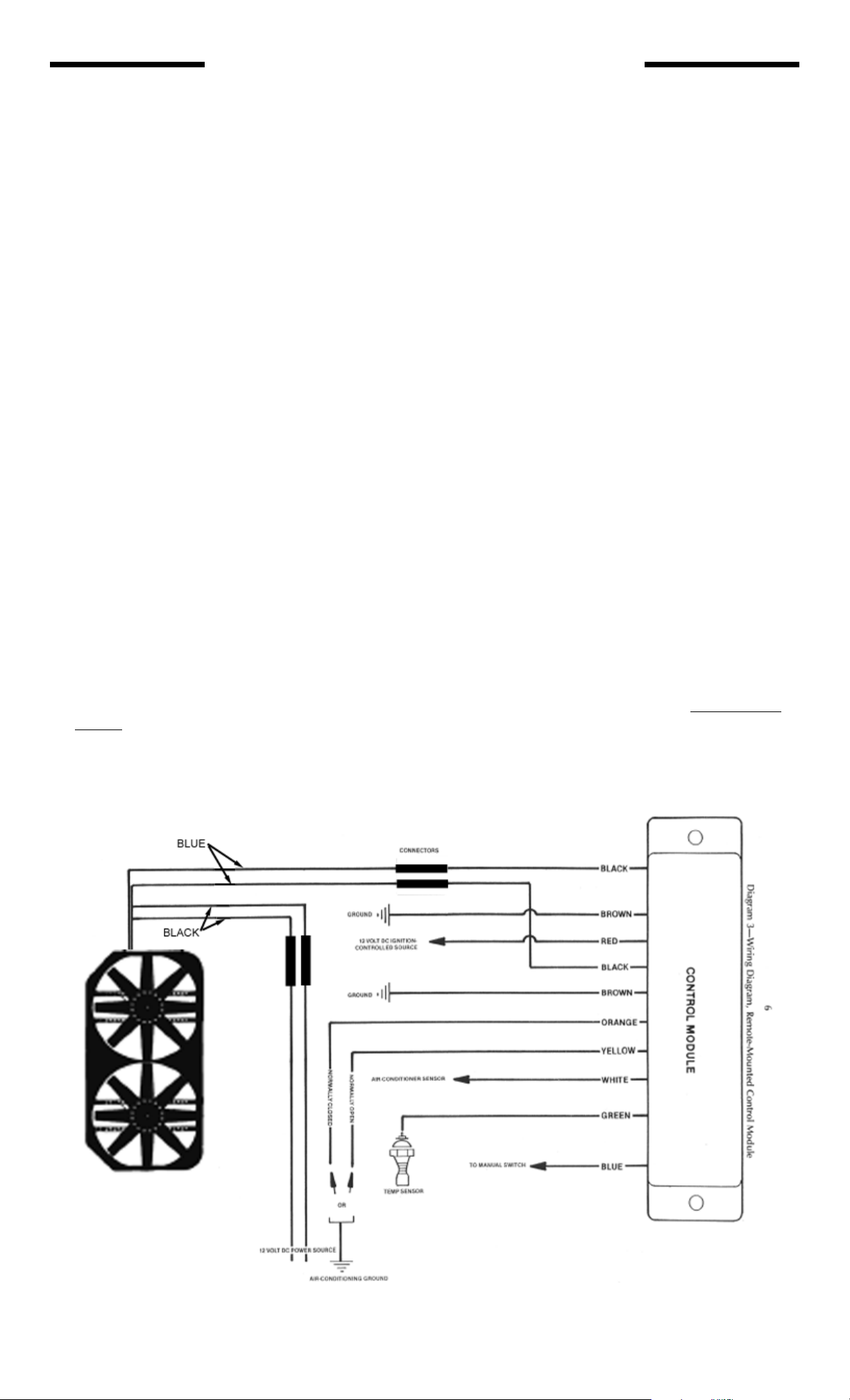
C. WIRING THE ELECTRICAL CONTROL MODULE: (Refer to Diagram 3.)
1. Black Wires (2)
Connect these wires with connectors which mate with the two black wires from the fan. If extra wire must be
used, be sure it is tie-wrapped.
2. Brown Wires (2)
Connect to a good single grounding point such as negative terminal of battery, engine, or frame rail.
NOTE: These wires carry the full current of the motors. For proper operation, a good grounding
point is imperative.
3. Red Wire (1)
Connect to a 12 volt DC ignition-controlled power source.
NOTE: The connecting point for this wire will not be the same source you used for the red wires
protruding from the shroud. The red wire from the control module must connect to an ignition-controlled source, and such sources typically cannot provide the amperage necessary to support fan
operation.
4. Green Wire (1)
Connect to the cooling temperature sensor. This is a ground signal switch.
Diagram 3 - Wiring Diagram
Remote-Mounted
Control Module
rev. 06-22-05 part no. 99993M Page 2 of 3
Page 3
D. AIR-CONDITIONING CONNECTIONS:
1. White Wire (1)
Connect to either the wire activating the air-conditioner compressor clutch (with a 3-way splice) or directly to the air-conditioning
activation sensor.
2. Orange Wire (1) OR Yellow Wire (1)
One of these wires is connected to ground, depending on whether the air-conditioning power source is normally open or normally
closed:
In a normally open air-conditioning circuit, the air-conditioner sensor wire (white wire) has no current flow when the airconditioner is off. When the air-conditioner is activated, current flows in this wire. In a normally open system, attach the yellow
wire to ground.
In a normally closed circuit, the air-conditioner sensor wire (white wire) has current flow when the air -conditioner is of f. When
the air-conditioner is activated, current flow will cease to flow in this wire. In a normally closed system, attach the orange wire to
ground.
After connecting the appropriate wire to ground, the remaining wire should be cut off and capped with a wire end cap. No connection is made with this wire.
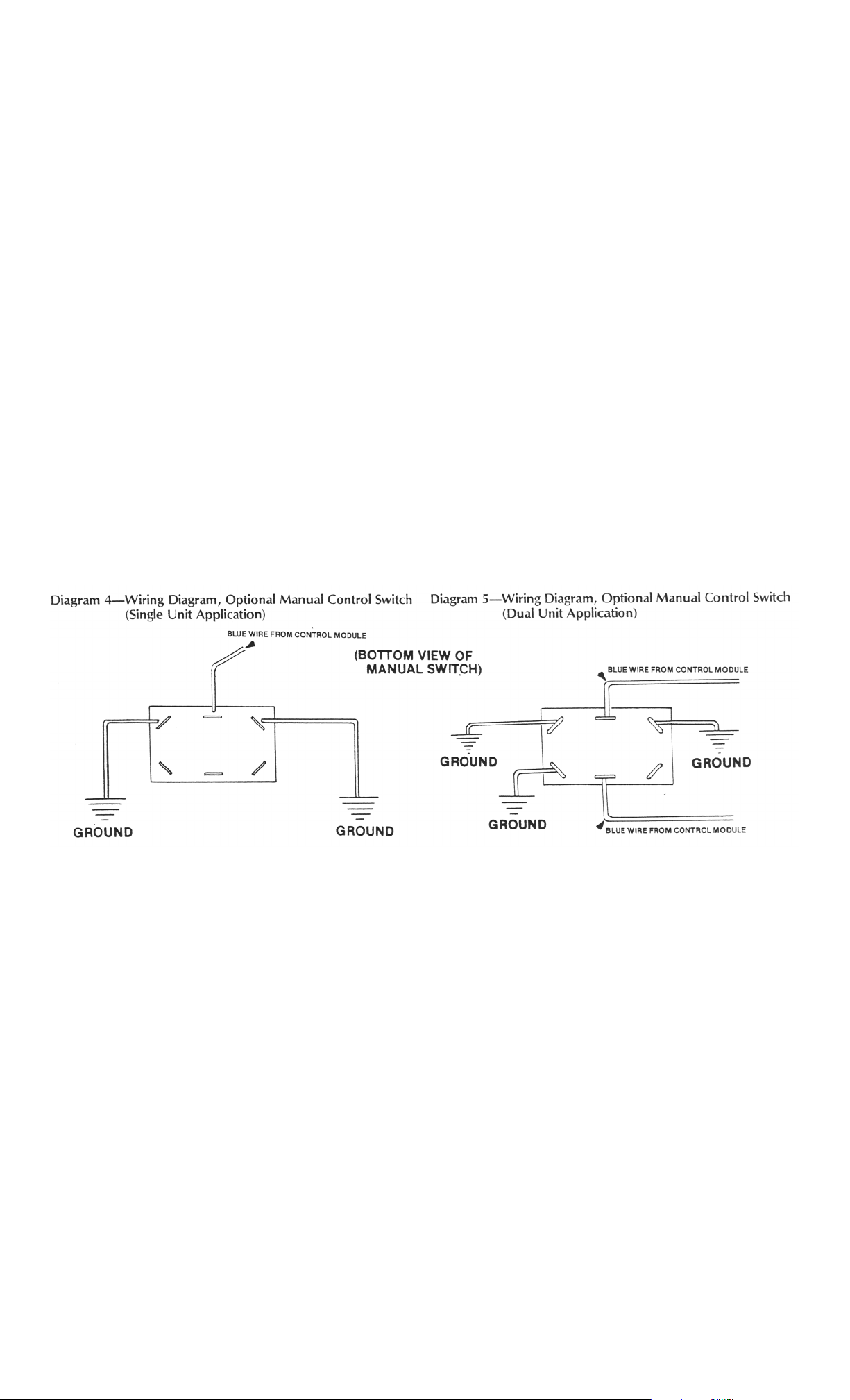
E. MANUAL SWITCH CONNECTION:
1. Blue Wire (1)
Attach the blue wire to Flex-a-lite's optional manual switch, part no. 30054, in accordance with Diagram 4 (for single unit installations) or Diagram 5 (for dual unit installations). Necessary quick-disconnect hardware is provided with the switch.
If you install another manufacturers switch, proceed according to the directions provided.
F. DUAL UNIT INSTALLATION:
Two electrical control modules are required for dual M350 installation. The 12 volt DC power source must be capable
of providing 100 amps of current. Two temperature sensors are used. Generally only one unit must be activated by the
air-conditioning system.
FINAL NOTE: After wiring the electrical control module, either:
A. Cut all unused wires as close to the module as possible; or
B. Bundle unused wires with the tie straps provided and secure to vehicle. Wire end caps provided in the kit should be
installed on all unused wires to prevent possible short circuits.
rev. 06-22-05 part no. 99993M Page 3 of 3
 Loading...