

Page 1

Part #525
89-94 Mitsubishi Eclipse
Be sure the engine is cool before starting work on the car . For added safety, disconnect the battery to keep the fans from
coming on while working under the hood. Please read all instructions before starting the installation.
Electric Cooling Fan Installation Instructions
FAN INSTALLATION (Diagram A)
1. Unplug, unbolt and remove fans from radiator.
2. Mount the FAL Eclip se fan to the existing radiator points with bracket s provided. Attach the large supplied bracket
to the top of the FAL fan shroud. Affix the smaller bracket to the lower lef t side of the FAL fan shroud. Both are
attached with the serrated phillips screws provided.
3. The spacers and long screws provided are necessary to bolt the assembly to the radiator. The factory radiator
requires the four long spacers and one short spacer . If it is an aftermarket radiator, a different spacer combination
may be needed.
Diagram A
Large Bracket
Washers
Short Screws
Long Screws
Washers
Small Bracket
Spacers (vary by
radiator)
rev.10-06-08 part no. 99749 Page 1 of 2
Page 2
WIRING INSTRUCTIONS
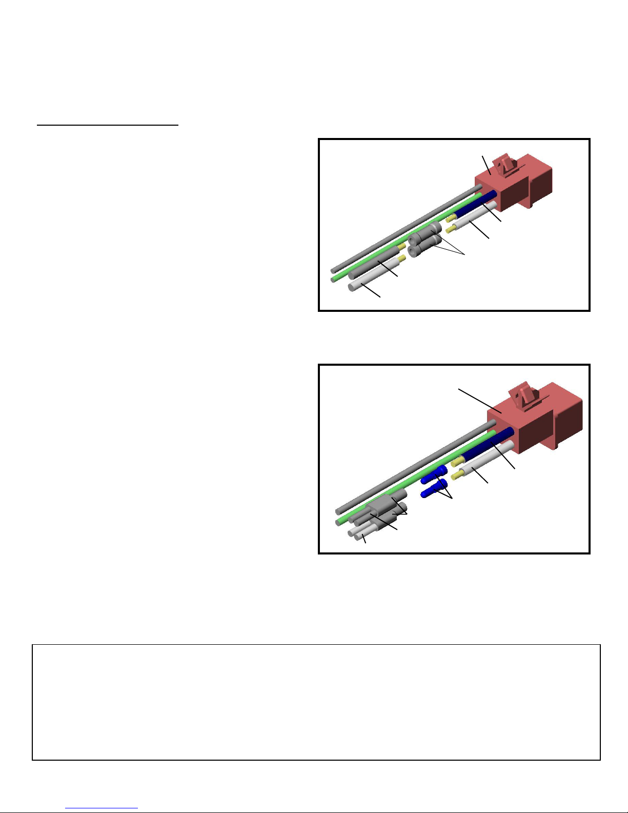
For cars with air conditioning: (Diagram B)
4. Take one of the factory plugs and clip the wires at
the attachment point to the factory fan. Remove
the two to one bullet connectors from the FAL fan
unit. Isolate a black and red set of wires that go to
one motor on the FAL unit and clip off the bullet
connectors.
5. Strip about 1/2” of insulation from the four wires.
Using the supplied butt connectors, connect the
blue wire from the factory wires to the colored wire
from the FAL fans. Connect the black wire from the
factory plug to the black wire on the FAL fan.
Secure the wires so they won’t interfere with
rotation of fans or other engine components.
Repeat steps 4 and 5 for the other fan and factory
plug.
For cars without air conditioning: (Diagram C)
4. Locate the factory plug for the electric fans. Clip
the black and blue wires that go to the electric fans.
Strip about 1/2” of insulation from the wire and
attach bullet connectors to these wires.
5. Insert the bullet connector that contains the blue
wire into the two to one connector on the FAL fan
unit that has both colored motor wires. Insert the
bullet connector with black wire into the two to one
bullet connector on the FAL fan unit that has both
black motor wires. Secure the wires so they won’t
interfere with rotation of fans or other engine
components.
Diagram B
Repeat for both
Factory Plug
plugs
FactoryBlack Wire
Factory Blue Wire
Butt Connectors
Black FAL Wire
Red FAL Wire
Colored Wires
Note: Wires shown in both diagrams are not to length
Diagram C
Factory Plug
Black Wire
Blue Wire
Bullet Connectors
Two to One Connectors
Black FAL Wires
Colored Wires
Red FAL Wires
The Flex-a-lite Limited Warranty
Flex-a-lite Consolidated, 7213-45th St. Ct. E., Fife, WA 98424, Telephone No. 253-922-2700, warrants to the original purchasing
user, that all Flex-a-lite products to be free of defects in material and workmanship for a period of 365 days (1 year) from date of
purchase. Flex-a-lite products failing within 365 days (1 year) from date of purchase may be returned to the factory through the
point of purchase, transportation charges prepaid. If, on inspection, cause of failure is determined to be defective material or
workmanship and not by misuse, accidental or improper installation, Flex-a-lite will replace the product free of charge, transportation prepaid. Flex-a-lite will not be liable for incidental, progressive or consequential damages. Some states do not allow the
exclusion or limitation of incidental or consequential damages, so the above limitation or exclusion may not apply to you. This
warranty gives you specific legal rights and you may have other rights, which vary from state to state. The Flex-a-lite warranty is in
compliance with the Magnuson-Moss Warranty Act of 1975.
rev. 10-06-08 part no. 99749 Page 2 of 2
 Loading...