

Flex-a-Lite Black Magic Extreme 185, Black Magic Xtreme 185 Installation Instructions Manual
Page 1
INSTALLATION INSTRUCTIONS
06-04-09 99185 Page 1 of 3
#185
Step 1: Remove Existing Fan & Shroud
Separate radiator overflow bottle from shroud and set aside. This will be installed with a new
shroud.
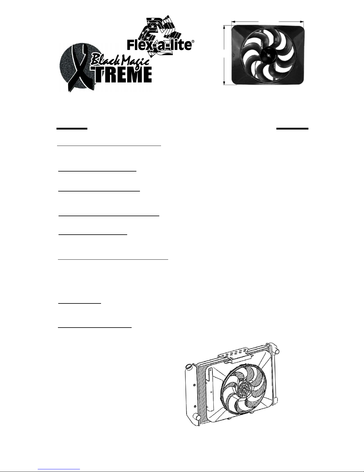
171/2"
213/8"
41/8" DEPTH
Must ang 5.0
Step 2: Mount overflow bottle
Mount bracket number 35234 to left side of shroud.
Step 3: Mount bottom brackets
Mount spacer and bottom bracket number 35235 to the bottom of the shroud. Leave brackets loose for
adjustment. Use the 2 long hex head screws provided.
Step 4: Mount top bracket with inserts
Mount bracket number 35233 to top of shroud.
Step 5: Mount top bracket
Mount top bracket number 35232 to inserts of bracket 35233.
Leave loose for adjustment.
Step 6: Locate mounting point for control
Locate a mounting point for control near passenger side of radiator.
Control needs to be placed within 18" of radiator inlet hose on
passenger side. You may want to mount next to radiator on
fender well or the corner of the fan shroud. Mount control using
screws provided
Step 7: Wire fan
Route motor wires through shroud, you may drill a 1/4" hole
and pass the wires through.
Step 8: Mount fan assembly
Mount fan assembly and tighten brackets. Adjust brackets to seal shroud to radiator core.
Put the fan into place. Before tightening the
brackets, adjust the fan so that the rubber
seal is contacting the radiator core and
compress the seal about 50%. It may help
to have a friend hold the fan against the
core while tightening brackets.
Page 2
CONTINUE TO NEXT PAGE TO COMPLETE THE INSTALLATION.
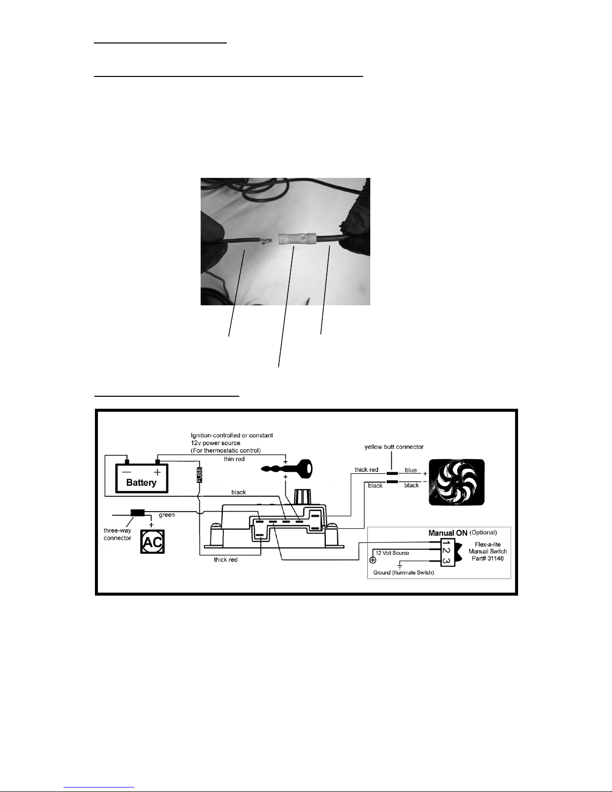
Y ellow butt connector
Crimp the motor wires to the large
supplied wire...
Large dia. red wire
Blue motor wire
Step 10: Wire the fan motors (refer to Wiring Diagram, below)
Using the yellow butt connectors provided, attach a length of the large diameter (10 AWG) red wire to
the blue motor wire. Attach a length of the large diameter (10 AWG) black wire to the black motor
wire. Once the fan is in place, these will attach to the control module. Tip: Strip an additional 1/8"
of insulation from the motor wires and fold them over to increase the thickness of the wire
where it will slide into the butt connector. If mounting the control module to the fan shroud, the
motor wires can be connected now (see wiring diagram, next page). If mounting the control somewhere else in the engine compartment, leave enough wire to reach the control module, but do not
connect yet.
Step 9: Mount overflow bottle
Mount overflow bottle to bracket using bolts and large washers provided.
Step 11: Wire the control module
11a. Connect the motor wires to the control module
(Red wire to the "M+" terminal and black wire to the "M-" terminal).
11b. Disconnect the negative battery lead for safety while finishing the wiring. Use the large diameter red (10 AWG) wire to run power directly from the battery positive (+) terminal to the "B" terminal
on the control module. Connect the fuse holder in-line with this wire, as shown, but do not insert the
fuse yet. Use the yellow female, ring, and butt connectors provided.
99185 Page 2 of 3
Page 3

11g. Use the zip ties provided to secure the wires and prevent them from interfering with fan
blades, belts, and pulleys in the engine compartment. Reconnect the battery and insert the
fuse provided.
11c. Use the large diameter black (10 AWG) wire to run from the negative (-) battery terminal to
the "G" terminal on the control module. Use the yellow female connector and ring connector
provided.
11d. Use the small diameter red wire (14 AWG) to connect the "+" terminal on the control
module to a positive power source. NOTE: Attaching this wire to an ignition-controlled
source will shut off the fan when the engine is turned off. Attach this wire to an
uninterrupted (always hot) power source to allow the fan to continue running after
the engine is shut off. Use the blue female connector and fuse taps (included) if neces-
sary.
11e. (Optional) For air conditioning control (if desired) connect the "C" terminal on the control
module to the positive wire that triggers the A/C compressor using the small diameter green (14
AWG) wire. Using a voltmeter, determine which wire coming from the compressor is the positive
trigger wire. Use the 3-way connector (included) to tap into this wire and send a signal to the fan
control module. The fan will cycle on and off with the A/C clutch when the A/C is turned on.
11f. (Optional) For manual switch operation, use Flex-a-lite p/n 31148. Connect the switch as
shown on the wiring diagram (previous page). Connect the "M" terminal on the control module to
the "1" terminal on the switch. Connect the "2" terminal on the switch to a positive 12v power
source. Connect terminal "3" on the switch to a good ground (for switch illumination). NOTE: To
prevent thermostatic activation (if only manual switch operation is desired), omit the lead
to the "+" terminal of the control box. "B", "G", "M+" and "M-" must remain connected. If
not using a Flex-a-lite manual switch, do not connect a ground wire to the switch!
Step 12: Insert the temperature probe into the radiator fins
Locate the inlet hose from the engine to the radiator. Remove the black insulator cap and insert
the temp. probe through the radiator fins near the inlet hose. Reinstall the black insulator cap.
Step 13: Adjust the temperature control knob on the control box
Install temp. probe near inlet hose...
then replace the insulator cap.
99185 Page 3 of 3
The Flex-a-lite Limited Warranty
Flex-a-lite Consolidated, 7213-45th St. Ct. E. Fife, WA 98424, Telephone No. 253-922-2700, warrants to the original purchasing user, that all Flex-a-lite products to be free of defects in material and
workmanship for a period of 365 days (1 year) from date of purchase. Flex-a-lite products failing within 365 days (1 year) from date of purchase may be returned to the factory through the point of
purchase, transportation charges prepaid. If, on inspection, cause of failure is determined to be defective material or workmanship and not by misuse, accidental or improper installation, Flex-a-lite will
replace the fan free of charge, transportation prepaid. Flex-a-lite will not be liable for incidental, progressive or consequential damages. Some states do not allow the exclusion or limitation of
incidental or consequential damages, so the above limitation or exclusion may not apply to you. This warranty gives you specific legal rights and you may have other rights, which vary from state to state.
The Flex-a-lite warranty is in compliance with the Magnuson-Moss Warranty Act of 1975.
If you disconnected any hoses or drained coolant to install the fan, reconnect the hoses and refill the
radiator. Press the control knob (included in wiring kit) onto the control box shaft. Turn the knob
clockwise until it stops. Start the engine and allow it to idle. Using a hand held thermometer (positioned near the inlet hose) or the vehicle's temperature guage, monitor the temperature. When the
coolant temp. is slightly above normal (or desired temp.), turn the knob counter-clockwise just until
the fan turns on. From now on, the fan should activate at this temperature setting. Adjust as necessary to maintain desired temperature.
 Loading...