

Page 1
Black Magic 165
for the TOYOTA 4 x 4 (1984-19964&6cyl.)
Prior to Electric Fan installation on all models:
1. Disconnect the battery.
2. Drain approx. 1 quart of fluid from the radiator using the petcock located on the bottom passenger side of the radiator. (see Diagram A)
3. Disconnect the top radiator hose and position it so it is out of the way.
Installation Instructions
4-Cylinder Applications
4. Remove the air tubing running between the throttle
body and the air filter / air flow meter housing.
(This is positioned directly over the original fan.)
5. Remove the (4) bolts and washers that fasten the
shroud to the radiator. Important: Save these bolts
and washers for use later. Remove the shroud.
6. Remove the (4) nuts that fasten the fan clutch to the
water pump pulley. Remove the clutch. (It is not
necessary to remove the fan from the fan clutch.)
7. Important: Because the water pump pulley studs are
not threaded completely, it is necessary to put 2 of the
smaller provided washers on each of the water pump
pulley studs; then replace the nuts and tighten.
6-Cylinder Applications
4. Remove the (4) bolts and washers that fasten the
shroud to the radiator. Important: Save these
bolts and washers for use later.
5. Remove the (4) nuts that fasten the fan clutch to the
water pump pulley. (It is not necessary to remove the fan
from the fan clutch.)
6. Remove the shroud, fan and clutch by lifting straight up
and out.
7. Important: Because the water pump pulley studs are
not threaded completely, it is necessary to put 2 of the
larger provided washers on each of the water pump pulley
studs; then replace the nuts and tighten.
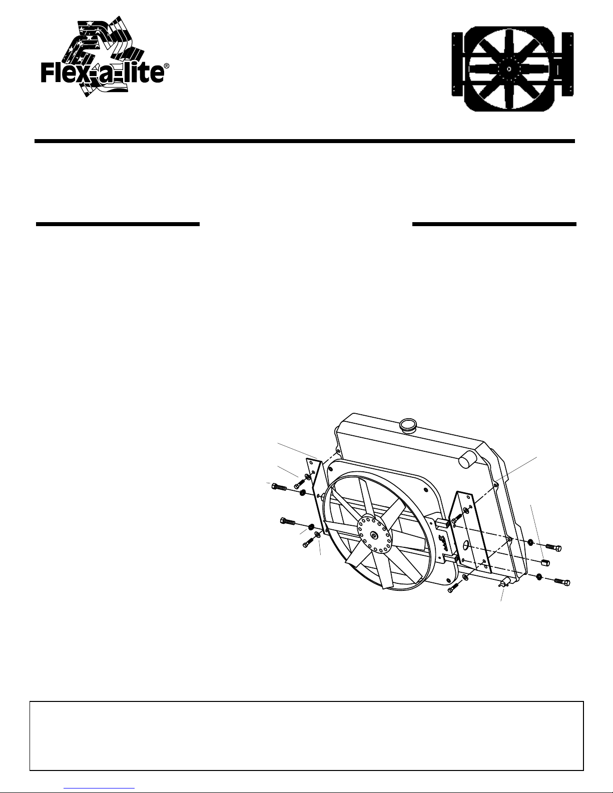
Diagram A
Angle Bracket (2)
Radiator Flange
Original Shroud Bolts
Square Tubing Bolts
Electric Fan Assembly
Control Knob
1. Attach the temperature control
knob to the control box.
2. Fasten the angle brackets to
Lock Washer (4)
the ends of the square tubing
using the (4) bolts provided.
Important: Do not tighten completely,
Original Shroud
(4) Washers
leave 1 full turn.
INSTALLING THE ELECTRIC FAN TO THE RADIATOR
1. Line the bolt holes of the angle brackets with the threaded bolt holes on the radiator flange. The control box will be
on the passengers side of the radiator, the electric fan shroud should be in line with the top radiator tank lip.
2. Bolt the electric fan unit to the radiator flange using the original shroud bolts and washers.
(see Diagram A)
3. Tighten the angle brackets to the electric fan.
The Flex-a-lite Limited Warranty
Flex-a-lite Consolidated, 7213-45th St. Ct. E., Fife, WA 98424, Telephone No. 253-922-2700, warrants to the original purchasing user, that all Flex-a-lite products to be free of
defects in material and workmanship for a period of 365 days (1 year) from date of purchase. Flex-a-lite products failing within 365 days (1 year) from date of purchase may
be returned to the factory through the point of purchase, transportation charges prepaid. If, on inspection, cause of failure is determined to be defective material or workmanship
and not by misuse, accidental or improper installation, Flex-a-lite will replace the fan free of charge, transportation prepaid. Flex-a-lite will not be liable for incidental,
progressive or consequential damages. Some states do not allow the exclusion or limitaion of incidental or consequential damages, so the above limitation or exclusion may
not apply to you. This warranty gives you specific legal rights and you may have other rights, which vary from state to state. The Flex-a-lite warranty is in compliance with
the Magnuson-Moss Warranty Act of 1975.
Rev. 10-19-09 part no. 99971 Page 1 of 2
Petcock
Page 2
POSITION CAPILLARY TUBE (See DIAGRAM B)
This temperature sensor sends engine coolant data to the temperature control for more efficient cooling of your vehicle. The temperature sensor needs to be carefully placed through the
radiator core to detect engine coolant temperature.
1. Locate your radiator inlet hose; one of two large hoses that attach to the radiator. The inlet
hose from the engine should be mounted higher than the other hose. Release the clip holding
the thin capillary tube. Mount the fan so you can reach the inlet hose with the temperature
probe. Be careful not to kink or pinch the capillary tube.
2. With a small Phillips style screwdriver, gently separate the cooling fins on the radiator near
the inlet hose. You will gently push the screwdriver through the radiator to create a hole for
the temperature sensor to rest. Move only the thin fins, do not disturb the thicker tubes
which carry the coolant through the radiator.
3. Remove the protective cap and gently push the temperature sensor through the hole. The
temperature sensor should fit snug in the core.
4. After placing the sensor, replace the plastic cap. It is important to replace the cap to prevent
the tube from pulling out of the radiator. The cap also insulates the sensor from cool air passing
through the grill.
5. Gently coil the extra capillary tube and place it out the way of moving
objects. Be careful no to kink the tube. If you must put a bend in the tube,
bend the tube around a pen or small bolt to prevent pinching the tube.
Diagram B
MANDATORY CONNECTIONS
1. Disconnect the battery negative terminal.
2. Connect the “+” terminal of the control box to a 12V positive (+) power source (i.e. fuse box), using the thin red wire
and fuse taps (if necessary) provided in the kit.
Note: Attach this wire to an ignition controlled source to stop the fan when the vehicle is shut off.
Note: Attach this wire to a non-ignition source to keep the fan running after the vehicle is shut off.
3. Connect the “B” terminal to a high amp 12V positive power source (i.e. battery, alternator) using the thick red wire
and in line fuse holder provided in the kit. (Do not install fuse at this time)
4. Connect the “G” terminal to ground (i.e. chassis, negative side of battery) using the thick black wire provided in the
kit.
5. If you have air conditioning: with 3-way connector provided, pass the A/C clutch positive(+) wire (connected to
the A/C compressor) through the connector. Place the thick green wire provided into the closed end of the connector.
Crimp metal plate. Snap plastic cover into place. Attach green wire to the "C" terminal of the
control box. Air Conditioning Relay activates fan when A/C is turned on
6. Insert probe in radiator core near upper hose. Install rubber cap over end of probe
ADJUSTING THE TEMPERATURE CONTROL
1. Attach the temperature control knob to the control box.
2. Turn the knob clockwise completely.
3. Idle the vehicle, observe the temperature of the vehicle.
(Use the vehicles gauge)
4. When the temperature of the vehicle reaches above
normal, turn the control knob counter-clockwise
until the fan turns on. From here on the fan should
activate at this temperature setting. Adjust as
necessary according to your vehicle needs.
OPTIONAL CONNECTIONS
Manual Switch (not included) - Allows
manual operation of the fan.
(This step is based on Flex-a-lite’s manual switch part
#31148, other switches will cause this unit to fail)
1. Connect the “M” terminal to terminal 1 on the switch.
2. Attach terminal 2 of the switch to a 12V positive (+)
source.
3. Attach terminal 3 of the switch to ground, in order to
illuminate the switch.
Note (optional): To stop the fan from activating
thermostatically, omit the lead to the “+” terminal of
the control box. “B”, “G”, & “M” must remain
connected.
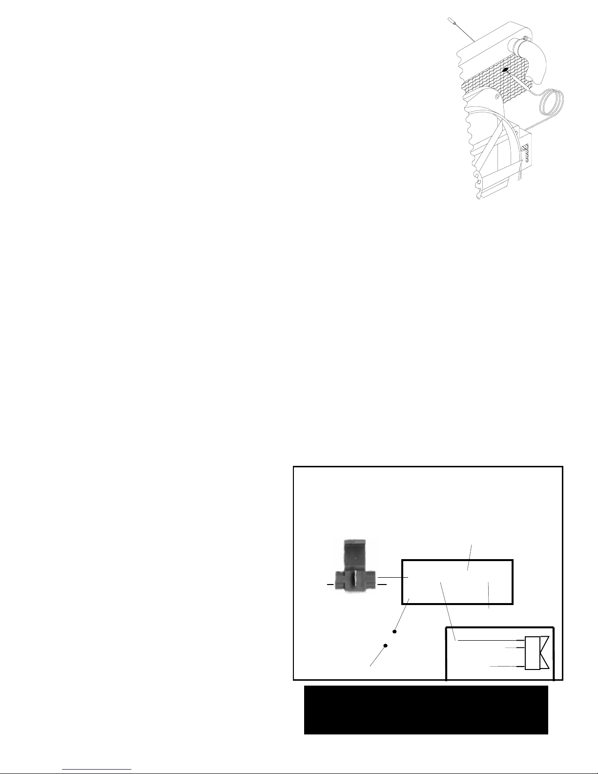
Control Box T erminals & Connections
Mandatory Connections
+ 12 volt positive source
G Ground
B 12 volt positive source
C Air conditioning relay
Optional Connection
M Manual switch
Ground
Control Box
G
+
12 V olt Positive Source
optional
12 Volt Source
Ground
(Illuminate switch)
3-way
connector
A/C positive (+)
wire from clutch
12 Volt Positive Source
C
B
Fuse Holder
M
*WARNING: If not using Flex-a-lite's
illuminated switch (PN #31148) you must
disconnect the switch ground.
Rev. 10-19-09 part no. 99971 Page 2 of 2
12 3
 Loading...