

Flex-a-Lite Black Magic 160, Black Magic 168, Black Magic S-blade 160, Black Magic S-blade 168 Installation Instructions Manual
Page 1
#160 & #168
Nut
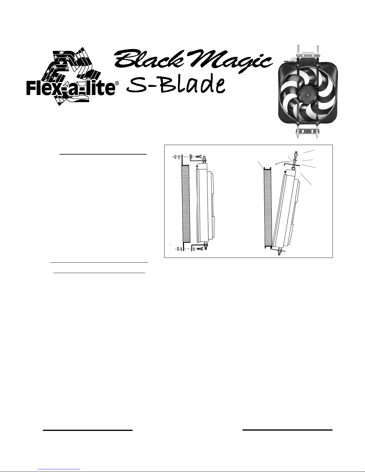
Mounting Instructions:
Models #160 & #168 may be installed
horizontally or vertically to the radiator.
Assemble the brackets and threaded
rods to the fan according to the specific
applicaiton. Mount the fan with brackets
using either the bolt-on or clamp-on
method.
nuts to stabilize the threaded rods.
Do not over-tighten to the radiator damage may occur.
NOTE:
Be sure to use star-
Bolt-on Method
Clamp-on Method
Radiator
Channel
Radiator
(Front)
Bracket
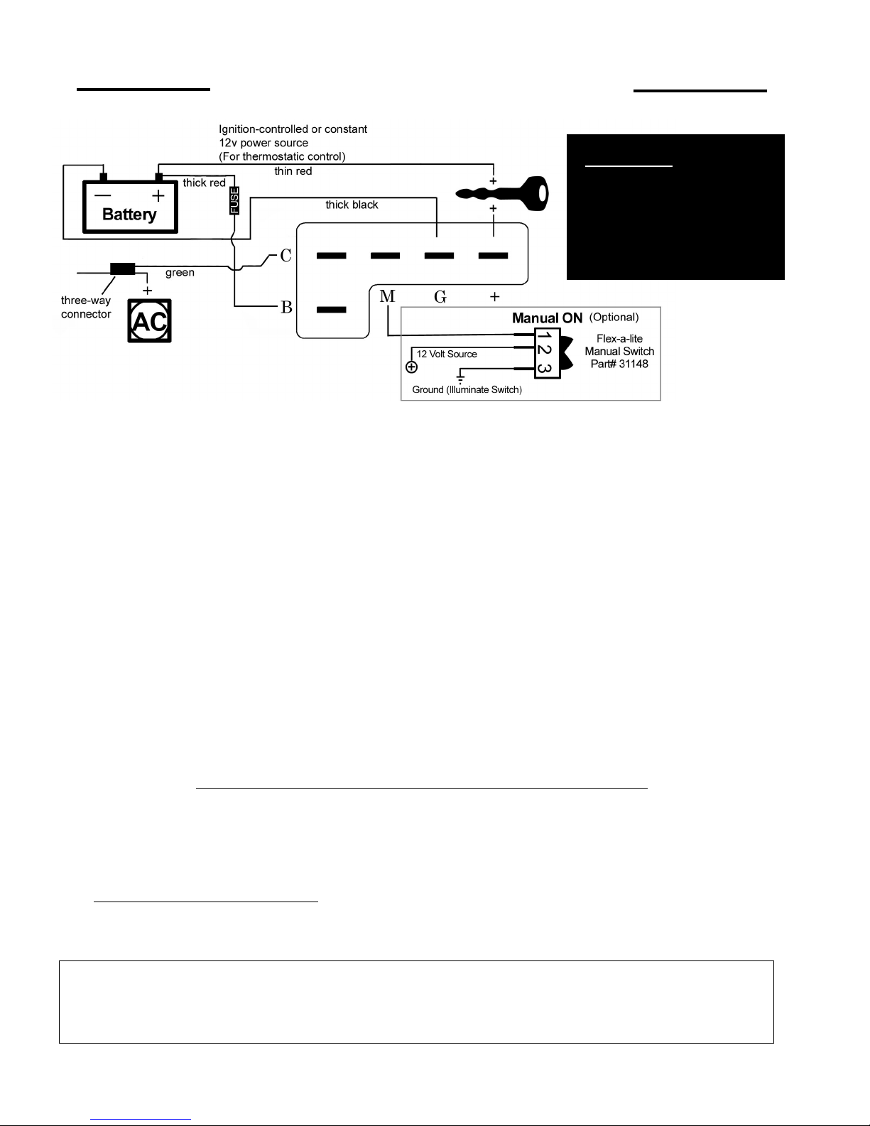
WIRING INSTRUCTIONS;
#160 with controls only
1. Disconnect the battery Negative (-) terminal
2. Connect the “B” terminal on the control to the 12 volt positive (+) battery terminal using the thick
red wire and fuse holder provided in the kit.
3. Connect the “G” terminal on the control to battery negative (ground - ) terminal using the thick
black wire provided in the kit. (Do not install fuse at this time)
4. Connect the “+” terminal of the control box to a keyed 12 volt positive (+) power source (i.e. fuse
box), using the thin red wire and fuse taps (if necessary) provided in the kit.
wire to an ignition controlled source to stop the fan when the vehicle is shut off. Attach
this wire to a constant source to keep the fan running after the vehicle is shut off.
5
. If you have air conditioning: With the 3-way connector provided, pass the A/C clutch posi-
tive(+) wire (connected to the A/C compressor) through the connector. Place the green wire
provided into the closed end of the connector. Crimp metal plate. Snap plastic cover into place.
Attach green wire to the "C" terminal of the control box.
when A/C is turned on
6. Insert temp. probe through radiator core near the upper (inlet) hose. Install rubber cap over end
of probe.
Air Conditioning Relay activates fan
NOTE
: Attach this
Nut
Washer
Threaded
Rod
St ar Nut
CONTINUE TO NEXT PAGE
Rev. 01-27-10 99975 page 1 of 2
Page 2
INSTALLATION (CONTINUED FROM PAGE 1)
*WARNING: If not using
Flex-a-lite's optional
illuminated switch (PN
#31148), you must
disconnect the switch
ground.
Note: To stop the fan from activating thermostatically, omit the lead to the “+” terminal of the control
box. “B”, “G”, & “M” must remain connected.
ADJUSTING THE TEMPERATURE CONTROL
1. Attach the temperature control knob to the control box.
2. Turn the knob clockwise completely.
3. Idle the vehicle, observe the temperature of the vehicle. (Use the vehicles gauge)
4. When the temperature of the vehicle reaches slightly above normal, turn the control knob counterclockwise until the fan turns on. From here on, the fan should activate at this temperature setting.
Adjust as necessary according to your vehicle needs.
OPTIONAL CONNECTIONS
Manual Switch (not included) - Allows manual operation of the fan.
(
This step is based on Flex-a-lite’s manual switch part #31148, other switches will cause this
unit to fail
).
1. Connect the “M” terminal to terminal 1 on the switch.
2. Attach terminal 2 of the switch to a 12V positive (+) source.
3. Attach terminal 3 of the switch to ground, in order to illuminate the switch.
WIRING INSTRUCTIONS; #168 with out controls
1. Wire the fan motor to power source (control unit or switch and relay if desired). Connect the
wire from the fan motor to a 12v. positive (+) source. Connect the
Black
motor wire to a ground
(-) source.
NOTE: Failure to do this will result in incorrect operation and damage to the fan motor!
2. Connect an inline fuse holder; Be shure to connect a fuse holder in-line with the positive (+)
power wire to protect the fan motor and your vehicle's electrical system from damage.
The Flex-a-lite Limited Warranty
Flex-a-lite Consolidated, 7213-45th St. Ct. E. Fife, WA 98424, Telephone No. 253-922-2700, warrants to the original purchasing user, that all Flex-a-lite products to be free of defects
in material and workmanship for a period of 365 days (1 year) from date of purchase. Flex-a-lite products failing within 365 days (1 year) from date of purchase may be returned to the
factory through the point of purchase, transportation charges prepaid. If, on inspection, cause of failure is determined to be defective material or workmanship and not by misuse,
accidental or improper installation, Flex-a-lite will replace the fan free of charge, transportation prepaid. Flex-a-lite will not be liable for incidental, progressive or consequential
damages. Some states do not allow the exclusion or limitation of incidental or consequential damages, so the above limitation or exclus ion may not apply to you. This warranty gives
you specific legal rights and you may have other rights, which vary from state to state. The Flex-a-lite warranty is in compliance with the Magnuson-Moss Warranty Act of 1975.
Blue
Rev. 01-27-10 99975 page 2 of 2
 Loading...