

Page 1
Toyota Tacoma Electric Fan Kit;
'05–'09
#678 with controls
#688 without controls
———INSTALLATION INSTRUCTIONS———
REMOVAL OF EXISTING FAN AND SHROUD ASSEMBLY:
1. Make sure the engine is cool.
2. Disconnect negative (-) battery cable from battery.
3. Remove plastic protective cover from top of engine / intake manifold. Two acorn nuts
located in front are to be removed first. Lift front of cover and notice the cover is hinging
at back. Pull to disconnect at pivot point.
4. Remove plastic cover bridging shroud to top cross member. (9 ea) Push-type plastic
rivets need to be removed (see Detail 1). Prying each center post up with a flat-end
screwdriver will release fastener.
5. Remove overflow hose from radiator filler neck.
6. Remove top bolts (2ea.) holding fan shroud to radiator side tanks. Save bolts for installation of new shroud (see Detail 2).
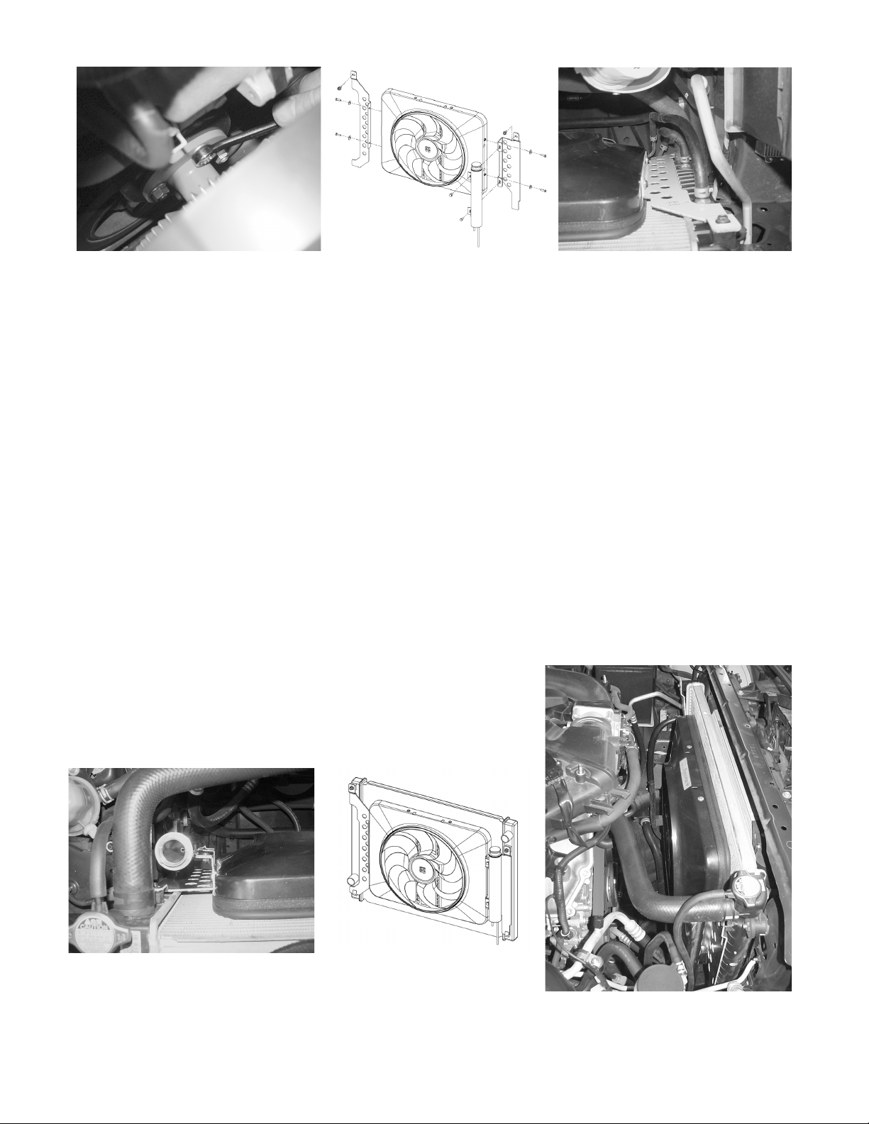
7. Remove (4ea.) nuts securing fan-clutch assembly (see Detail 3); then pull fan-clutch
assembly and shroud out simultaneously.
8. Important: Re-secure pulley with new washers of kit bag #13615 and original pulley
nuts.
Plastic Cover
Save bolts for new installation
Detail 1
Detail 2
Plastic Rivets
rev. 04-20-09 part no. 99678 Page 1 of 4
Page 2
Detail 3
Detail 4a
INSTALLATION OF NEW ELECTRIC FAN SHROUD:
1. Mount bracket #67802 to driver’s side of shroud. Use the hex bolts and washers provided. Note:
Leave the bracket loosely mounted for now; you will adjust and tighten them later (see Detail 4 &
4a).
2. Lower shroud, with one bracket only, into position inserting bottom of bracket into slot at bottom
of side tank (driver’s side). Loosely secure top of bracket using factory bolt, saved from step #6
of page 1
3. Attach overflow tank to bracket #67801 using supplied hardware included with overflow tank (see
Detail 4 & 4b).
4. Attach bracket #67801 to passenger’s side radiator tank and fan shroud;
a. Insert bottom of bracket into slot at bottom of side tank.
b. Loosely secure top of bracket using factory bolt, saved from step #6.
c. Mount bracket loosely to shroud using the hex bolts and washers provided (see Detail 4
& 4b).
5. After both brackets and shroud are attached; make final adjustments utilizing slots provided.
When tightening the brackets, adjust the fan so that the rubber seal is contacting the radiator
core and compress the seal about ~50%. Note: It may help to have a friend hold the fan against
the core while tightening brackets.
6. Mount rubber hose supplied to radiator filler neck and to the shorter of the two tubes protruding
from bottom of overflow tank (see Detail 4).
7. If you disconnected any hoses or drained coolant to install
the fan, reconnect the hoses and refill the radiator. At this
time fill overflow tank ~25% of capacity.
Detail 4b
Detail 5
Finished Installation
rev. 04-20-09 part no. 99678 Page 2 of 4
Page 3

Wiring Diagram
Thick Red
Thick
Black
Colored
Black
1. Connect the motor wires to the control module (Red wire to the "M+" terminal and black
wire to the "M-" terminal).
2. Use the large diameter red (10 AWG) wire to run power directly from the battery positive (+)
terminal to the "B" terminal on the control module. Connect the fuse holder in-line with this
wire, as shown, but do not insert the fuse yet. Use the yellow female, ring, and butt connectors provided.
3. Use the large diameter black (10 AWG) wire to run from the negative (-) battery terminal to
the "G" terminal on the control module. Use the yellow female connector and ring connector
provided.
4. Use the small diameter red wire (14 AWG) to connect the "+" terminal on the control module to a positive power source. NOTE: Attaching this wire to an ignition-controlled source
will shut off the fan when the engine is turned off. Attach this wire to an uninterrupted
(always hot) power source to allow the fan to continue running after the engine is shut
off. Use the blue female connector and fuse taps (included) if necessary.
5. (Mandatory) With air conditioning, connect the "C" terminal on the control module to the
positive wire that triggers the A/C compressor using the small diameter green (14 AWG) wire.
Using a voltmeter, determine which wire coming from the compressor is the positive trigger
wire. Use the 3-way connector (included) to tap into this wire and send a signal to the fan
control module. The fan will cycle on and off with the A/C clutch when the A/C is turned on.
6. (Optional) For manual switch operation, use Flex-a-lite p/n 31148. Connect the switch as
shown on the wiring diagram (previous page). Connect the "M" terminal on the control module
to the "1" terminal on the switch. Connect the "2" terminal on the switch to a positive 12v
power source. Connect terminal "3" on the switch to a good ground (for switch illumination).
NOTE: To prevent thermostatic activation (if only manual switch operation is desired),
omit the lead to the "+" terminal of the control box. "B", "G", "M+" and "M-" must remain connected. If not using a Flex-a-lite manual switch, do not connect a ground wire
to the switch!
rev. 04-20-09 part no. 99678 Page 3 of 4
Page 4

7. Use the zip ties provided to secure the wires and prevent them from interfering with fan
blades, belts, and pulleys in the engine compartment. Insert the fuse provided.
8. Locate the inlet hose from the engine to the radiator. Remove the black insulator cap
from the temperature probe then insert the temp. probe through the radiator fins near
the inlet hose. Reinstall the black insulator cap.
Install temp. probe near inlet hose...
7. Press the control knob (included in wiring kit) onto the control box shaft. Turn the knob
clockwise until it stops.
8. Reconnect negative (-) battery cable to battery. Start the engine and allow it to idle.
Using a hand held thermometer (positioned near the inlet hose) or the vehicle’s temperature gauge, monitor the temperature. When the coolant temp is slightly above
normal (or desired temp.), turn the knob counter-clockwise just until the fan turns on.
From now on, the fan should activate at this temperature setting. Adjust as necessary to
maintain desired temperature.
After the engine has been at normal operating temperature for ~45 minutes, adjust over-
flow tank coolant level to be at ~50% capacity.
WW
iring Instriring Instr
W
iring Instr
WW
iring Instriring Instr
Wire the fan motor to power source (control unit or switch and relay if desired).
1. Connect the colored wire from the fan motor to a 12 volt positive (+) source. Be sure to
connect an inline fuse holder with a 30 amp fuse to the positive (+) power wire to protect the fan motor and your vehicle’s electrical system from damage.
2. Connect the black motor wire to a ground (-) source.
NOTE: failure to do this will result in incorrect operation and damage to the fan motor!
uctions – Model #688 ONLuctions – Model #688 ONL
uctions – Model #688 ONL
uctions – Model #688 ONLuctions – Model #688 ONL
then replace the insulator cap.
Y!Y!
Y!
Y!Y!
After the engine has been at normal operating temperature for ~45 minutes, adjust over-
flow tank coolant level to be at ~50% capacity.
The Flex-a-lite Limited Warranty
Flex-a-lite Consolidated, 7213-45th St. Ct. E. Fife, WA 98424, Telephone No. 253-922-2700, warrants to the original purchasing user, that all Flex-a-lite products to be free of defects
in material and workmanship for a period of 365 days (1 year) from date of purchase. Flex-a-lite products failing within 365 days (1 year) from date of purchase may be returned to
the factory through the point of purchase, transportation charges prepaid. If, on inspection, cause of failure is determined to be defective material or workmanship and not by misuse,
accidental or improper installation, Flex-a-lite will replace the fan free of charge, transportation prepaid. Flex-a-lite will not be liable for incidental, progressive or consequential
damages. Some states do not allow the exclusion or limitaion of incidental or consequential damages, so the above limitation or exclusion may not apply to you. This warranty gives
you specific legal rights and you may have other rights, which vary from state to state. The Flex-a-lite warranty is in compliance with the Magnuson-Moss Warranty Act of 1975.
rev. 04-20-09 part no. 99678 Page 4 of 4
 Loading...