

Page 1
Note: always read instructions and verify kit contents prior to installation.
Radiator ............................................... 1ea. Electrical Connector Kit ........................ 1ea.
Pre-Mounted Fan ................................. 1ea. VSC Controller Kit ................................ 1ea.
Bracket, Top Rad. Mount Left Hand ...... 1ea. Wire Bundle ........................................ 1ea.
Bracket, Top Rad. Mount Right Hand .... 1ea. Instruction Sheet ................................. 1ea.
Mounting Hardware Kit ........................ 1ea. Flex-a-lite Decal ................................... 1ea.
Installation Instructions For:
#57001 Radiator GM Truck/SUV
#57291 Radiator & Fan GM Truck/SUV
Fits MOST 1999-2012 Vehicles
(Vehicles with automatic transmission will require cooler kit #4118GMT,
sold separately, prior to installation)
Rev. 04-01-13 #99291 Page #1 of 6
Note: To view these instructions or to view a video of this product installation, visit
www.flex-a-lite.com or call 1-800-851-1510 for assistance. It is HIGHLY recommended to
read and review these instructions prior to installation.
Removal of Old Radiator and Fan (if needed):
1. As a safety precaution, be sure the vehicle is COOL enough to work on; also disconnect the negative (-)
battery cable.
2. Open the radiator fill cap. Locate the radiator drain and drain the radiator fluid into a spill-resistant
container.
3. Remove the plastic cover from the top of the radiator that covers the front support. Use a flat-head
screwdriver to pop and release the push-clips.
4. For ease of removal and installation, remove the air intake box and tube. This will be re-installed after
final installation.
5. Remove the upper fan shroud: The fan shroud is made of a top half and a lower half. Remove the
upper hose from the radiator inlet. Release the plastic hose clamp securing upper hose routed along
top of upper shroud. Pop the push-clips that hold the upper half to the lower half. Remove the 2 upper
bolts that hold the upper shroud to the top cross member. At this point, this upper half should be free.
Remove this upper shroud from the vehicle, save the plastic factory hose clamp by removing it from
the shroud. This will be used later to re-secure the upper hose.
6. Remove the clutch fan: Support the clutch face and/or fan while spinning the nut of the fan counter-
clockwise with a 1-3/8” open-end wrench. Spin completely off and remove the fan from the vehicle.
7. Remove the lower shroud: Pull up on the lower shroud which sits in saddles with tabs.
8. Disconnect the rest of the radiator hoses: The overflow tank and steam hose will come off. Then
remove the transmission hoses (if applicable) by pulling the retaining ring away from the tank
connection and pulling the “C” clip off of the connection by pulling up with a scribe or small flat-end
screwdriver. Finally, disconnect the main outlet hose at the bottom of the radiator over the drain
container. Use a rag or plug for these ports as they may leak upon removal.
9. Remove the radiator: Remove the 2 bolts from the top flanges located at both sides of the radiator.
This will free the radiator. Tilt the radiator towards the engine and lift slowly as to not damage the
radiator or any other components. Note: Save the 4 rubber bushings from the factory radiator (2 at top
and 2 at bottom. These will be used later in the install of the new radiator.)
Installation of the New Radiator and Fan (if required):
1. Placing the radiator: Place the factory lower bushings in the lower radiator support on the vehicle. The
driver’s side may have 2 locations for placement. Use the nearest location to the center of the vehicle.
Once these are in place, lower the radiator into place as the guide pins of the new radiator seat into
the bushings.
2. Upper Radiator Mounts: Find the left and right upper mounting brackets and slide on the factory upper
bushings. Loosely mount the brackets to the left and right on the top/engine side of the radiator
utilizing the supplied T-bolts, washers and nylock nuts. Use the upper factory bolts to mount the
radiator to the original support locations. Tighten those first, then snug up the nuts on the T-bolts of
the radiator.
3. Connect Hoses: Place the hose nipples to the tanks if necessary for the overflow and the steam port
with thread tape. Do not over-tighten! Then, connect the overflow and steam port hoses. Bolt the
short side of the tube support bracket to the inside drivers side threaded insert in the shroud. Connect
Page 2
Detail 1
Detail 2
the plastic factory hose clamp to this bracket then connect the larger upper inlet hose to the driver
FOLLOW THESE INSTRUCTIONS CAREFULLY TO AVOID DAMAGING THE CONTROL
UNIT, FAN MOTORS, AND YOUR VEHICLE! WHEN CRIMPING WIRES, ALWAYS USE
A QUALITY CRIMPING TOOL (DO NOT USE PLIERS OR OTHER DEVICES)
Rev. 04-01-13 #99291 Page #2 of 6
side.
4. Install the automatic transmission cooler (if applicable): Start by removing the factory grill to expose
the front side of the A/C condenser area. This consists of 4 twist-lock fasteners (2 top and 2 bottom)
turning about ¼ turn counter-clockwise to release. There is one bolt by the hood latch in the center.
When these are loose, the grill has some clips out by the headlamps that can be “gently” pulled out to
remove. The grill should come off in one piece. Note: This removal process works with the early
generation. You may need to consult your maintenance manual for newer vehicles.
5. Remove existing cooler (if applicable): Because the existing cooler is designed to run through the
radiator tank for additional cooling, there is no longer a place to connect these. Using Flex-a-lite cooler
kit #4118GMT, we can replace this with a higher capacity cooler for direct transmission cooling.
Disconnect the tubes by pulling the retaining “C” clips with a pick or small flat-head screwdriver and
remove the oil lines. Keep a drainage container and rags handy as the factory cooler still contains fluid.
Remove all the bolts holding the oil cooler and existing brackets. Retain the factory bolts for later
installation.
6. Temp Sensor: There is an ambient temperature sensor that “may” be located on the driver’s side of the
cooler. Unbolt but do not remove. Finish removing the cooler.
7. Mount #GMT4118 cooler into place with factory mounting locations and fasteners:
Note: To mount the upper portion, some models may require drilling a 7/32” hole into the support and
using the provided self-tapping screws to mount. Caution!! Do not go ALL the way thru the cooler
support; this could damage the A/C condenser.
8. Re-Install Temp Sensor: Use the bracket contained in the kit to sandwich between the bolt and the new
cooler bracket in the lower driver’s side. Attach the temp sensor with proper side facing the grill.
9. Connect Cooler Lines: Splice into the factory lines coming from the transmission. Use the barbed
adapters provided in the kit to connect the lines to the new cooler. Routing these lines to the
passenger side is ideal.
10. Replace the Fluids: Fill the radiator with the factory recommended coolant. Add factory recommended
transmission fluid to the appropriate level. Note: It is recommended to follow factory maintenance
procedures to re-fill the system and check after the engine has run for some time to verify proper levels
prior to operation.
Wiring Instructions Model #57291
1. Find a convenient location to mount the Variable Speed Control
(VSC). Note: If you choose to mount controller to face of shroud,
follow these mounting instructions. Attach the VSC directly to
the top or front face of the fan shroud. Using the holes in the
controller cover for a template, drill two 5/32” holes. Secure the
VSC with the 2ea. screws provided. (see Detail 1)
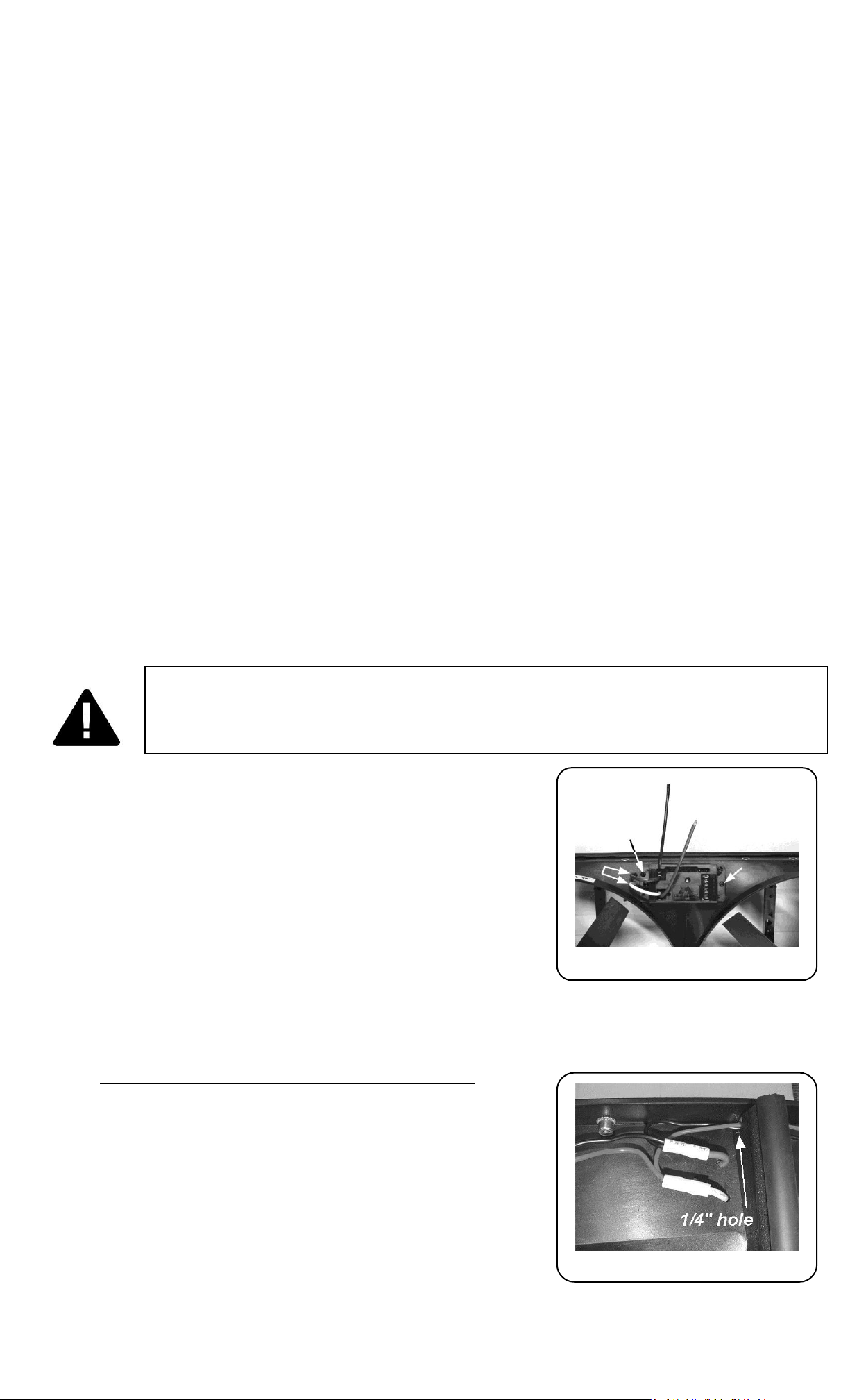
2. Drill two ¼” holes to the left of the VSC to pass the yellow and
purple wires through to the back side of the shroud (see Detail 1).
Drill one ¼” hole in the support rib on the back side of the shroud
to pass the motor wires through. (see Detail 1 & 2)
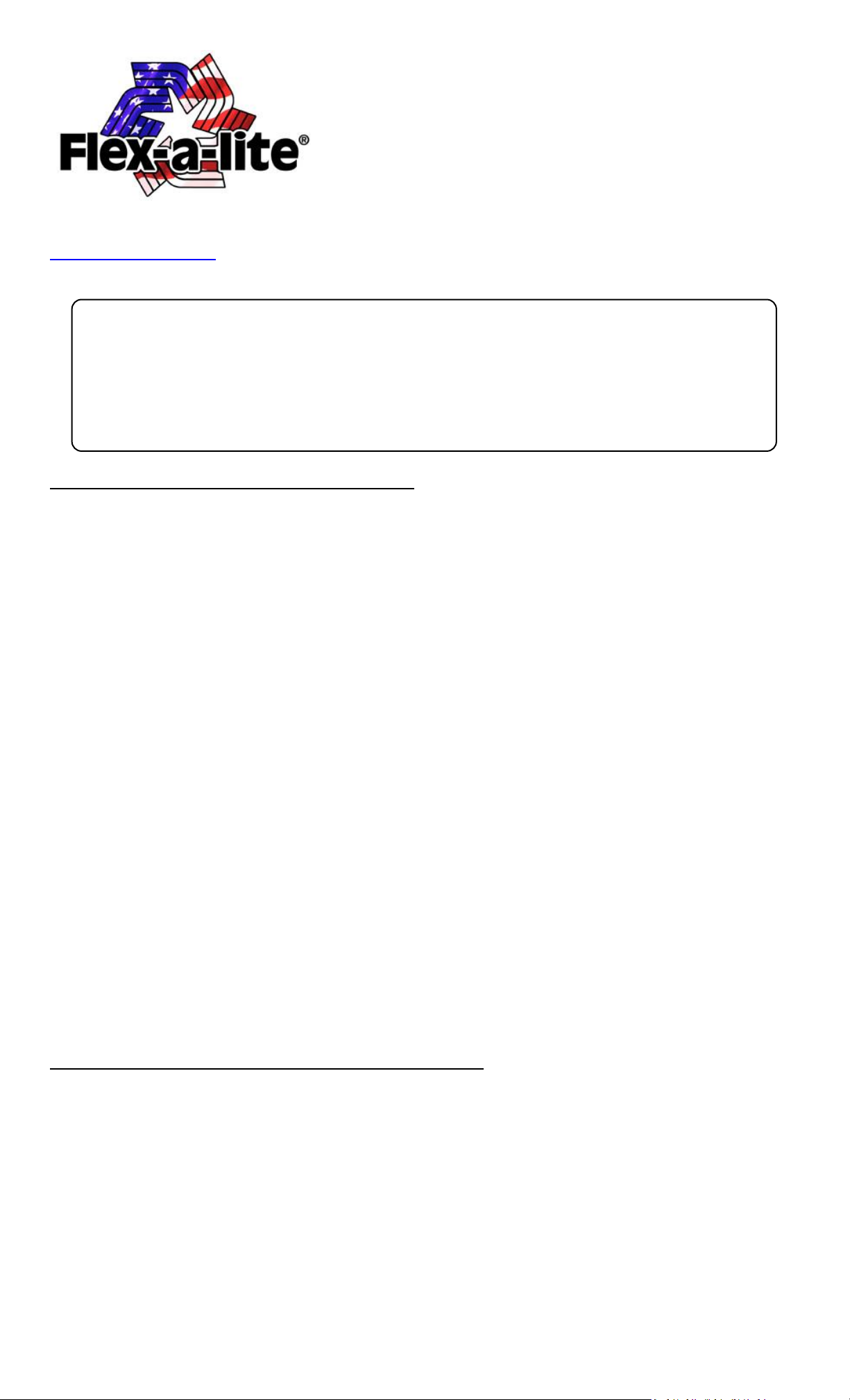
3. Place both red motor wires side by side and smoothly twist together. Completely insert pair of wires
into one end of yellow butt connector. Crimp connector to secure. Repeat with black motor wires to
another yellow insulated butt connector.
Red motor wire is (+) positive and black is (-) negative.
4. Feed the thick purple and yellow wires from the control unit
through the holes you drilled in step #2.
5. Insert yellow wire into the open end of butt connector
containing the two red motor wires and crimp connector
securely. Insert purple into the open end of butt connector
containing the two black motor wires and crimp connector
securely. (see Detail 3)
6. Determine the length of wire needed to connect the red and
black VSC power leads to the battery terminals and trim
appropriately. Crimp a large yellow ring connector to the end of the black wire and connect to the
negative (-) battery terminal, but do not connect the red wire yet.
Page 3

When crimping the temp
probe wires, strip back the
insulation, and then fold
wire back on itself to double
thickness
7. Find a convenient place to mount the circuit breaker between
Detail 3
Install the temp probe near
the inlet hose, leaving ¼” of
the probe protruding from
the core
Rev. 04-01-13 #99291 Page #3 of 6
the VSC and the battery positive (+) terminal and use the two
screws provided to mount it. Cut the red wire at the point where
you mounted the breaker. Find the red boot and lay it on the
breaker as shown in Detail 3. Connect small yellow ring
connectors to the ends of the wires and attach them to the
circuit breakers. NOTE: BE SURE TO CONNECT THE END COMING
FROM THE BATTERY (+) TO THE “BAT” TERMINAL ON THE
BREAKER (COPPER COLORED).
Now press the top of the boot over the breaker terminals to protect from arcing. Connect a large ring
connector to the junction box end and connect it to the terminal as shown.
8. Locate fuse box. Find a circuit that is “hot” when the key is in the “ON” position. NOTE: DO NOT use
the day time running lights or brake/taillight fuse, or any fuse directly related to the fuel or ignition
system! Attach the included fuse tap to the fuse. Attach a pink female connector to the thin red wire
included and connect to the fuse tap. Trim the wire so that it will reach the VSC. Attach a pink female
connector to the other end of wire and connect to terminal #9 on the VSC.
9. Locate the wires going to the A/C clutch. Determine which wire is ground
and which wire is positive by using a volt meter. Connect or splice the thin
green wire to the positive (+) wire of the A/C compressor using the blue
“Piggy-Back” connector. Determine length of green wire needed to reach
VSC. Rout green wire then trim to length. Attach a pink female connector
to the wire. Connect this wire to terminal #8 on VSC.
10. Locate the temperature probe. Gently push probe through fins in radiator
as close to the upper radiator hose as possible, leaving about ¼” of the probe protruding out of the
core. The rubber cap will not be used in this application. Determine length of wire needed to reach
VSC.
IMPORTANT: Strip insulation back about 1” and fold the wire onto itself to
effectively double the thickness of the wire before connecting the pink
female connectors. Then attach this wires to terminals #10 & #11. Both
wires need to be connected but it doesn’t matter which wire goes to each
terminal.
11. If manual switches (Flex-a-lite #31148) have been purchased, attach them
as follows: to override engine temperature to turn fans off, connect the
switch to terminal #5 on VSC to send a negative (-) signal. To override
engine temperature to turn fans on, connect the switch to terminal #6 on
the VSC so that the negative (-) signal is sent.
Page 4

Initial start-up and Adjustment Procedure
The Variable Speed Control features
At the set temperature, the fans will come on at 60%;
This reduces the load on your charging system. If the
temperature rises, the fan speed will increase. If your
set temperature is 195° and 205° the fan speed will
increase from 60% to 10%. So after a 10-degree rise
from the set point, the fans will be running at 100%.
The Flex-a-lite Limited Warranty:
Flex-a-lite Consolidated, 7009-45th Street Court East, Fife, Washington 98424. Telephone No. 253-922-2700, warrants to the original
purchasing user, that all Flex-a-lite products to be free of defects in material and workmanship for a period of 365 days (1 year) from the
date of purchase. Flex-a-lite products falling within 365 days (1 year) may be returned to the factory through the point of purchase,
transportation charges prepaid. If, on inspection, cause of failure is determined to be defective material or workmanship and not by
misuse, accidental or improper installation, Flex-a-lite will replace the product free of charge, transportation prepaid. Flex-a-lite will not
be liable for incidental, progressive or consequential damages. Some states do not allow the exclusion or limitation of incidental or
consequential damages, so the above limitation or exclusion may not apply to you. This warranty gives you specific legal rights and you
may have other rights, which vary from state to state. The Flex-a-lite warranty is in compliance with the Magnuson-Moss Warranty Act of
1975.
Rev. 04-01-13 #99291 Page #4 of 6
1. Turn ignition on. After 6 seconds, LED #L4 should light up. If not, check to make sure that there is 12
Volts at terminal #9 on VSC. The delay is to allow starter to start the vehicle without the fans drawing
any power.
2. With your engine running, engage the A/C. The fans should come on and cycle with the A/C clutch. LED
#L1, L3 and L4 should be lit when the fans are running. If they do not turn on, verify that the A/C clutch
is engaged and make sure you have a positive signal when the clutch is engaged at terminal #8 on the
VSC. Shut off A/C and let engine continue to idle, or drive the vehicle a short distance to bring the
engine to operating temperature (monitor the engine’s temperature gauge).
3. Verify that operating temperature has been reached by feeling the upper radiator hose. Hot coolant
should be flowing through the hose into the radiator. If the fans have not cycled on yet, slowly adjust
the screw on the VSC until the fans cycle on. Turning the screw counterclockwise will keep the engine
at a lower temperature, and turning in the opposite direction, clockwise, will keep the engine at a
higher temperature. NOTE: THE TOTAL MOVEMENT OF THE ADJUSTMENT SCREW IS ABOUT ¾ OF A
TURN. TURNING THE SCREW BEYOND THE LIMITS WILL DAMAGE THE UNIT! Once desired
temperature is set, let the engine continue to idle and make sure the fans will continue to cycle to
maintain desired temperature. When the fans are running, LED’s #L1 and L4 should be lit.
To Register Your Product:
Visit our website @ www.flex-a-lite.com/warranty-registration
Page 5

Flex-a-lite Consolidated limited warranty
Flex-a-lite Consolidated warrants its aluminum radiators to be free from defects in materials and workmanship
for a period of one year from the date of purchase at retail by the original purchaser. This warranty is extended
only to the first purchaser of any such radiator at retail. If the Flex-a-lite radiator is used in any racing
application, repaired or altered, this warranty is considered null and void, it also does not cover any radiator
repaired or altered in any way. If products such as transmission cooler or electric fan are attached with cable
ties or similar fasteners that run through the radiator core, the warranty is voided.
This warranty does not cover labor, materials not manufactured by Flex-a-lite, or shipping charges. The retail
purchaser is responsible for the appropriate use and application of the product. This warranty does not cover
the effects of physical or chemical properties of water, steam, or other liquids used in the radiator. Radiators
used without an adequate proportion of premium quality antifreeze/coolant are not covered by this warranty.
Flex-a-lite aluminum radiators require a correct proportion of quality coolant, which contains aluminum
corrosion inhibitors in the formula.
Claims for internal damage of the engine, components, or user’s vehicles are not covered by this warranty. It is
the responsibility of the Flex-a-lite product user to monitor engine operation and have proper detection
devices installed to warn the user of overheating. Specific exemptions to the warranty include tube damage,
ballooning or bursting from excessive engine operating temperature, internal corrosion due to inadequate
proportions of antifreeze/coolant, or damage to radiator resulting from a collision damage.
Flex-a-lite shall not be responsible for damages to its product or injury to persons using the product when
improperly opening radiator pressure caps, burst hoses, etc. Flex-a-lite shall not be responsible for injury or
harm to persons or property caused by persons or vehicles using our products.
The purchaser’s remedy for breach of this warranty, exclusive of all other remedies provided by law, is
expressly limited to repair or replacement of any part or parts. All products returned for warranty
consideration must be returned through the point of purchase with all transportation expenses prepaid. Upon
receipt of the product, Flex-a-lite will examine the product to determine the condition and validity of the claim.
Radiators or products received, which were damaged in shipping, should immediately be reported to the
shipping carrier as damaged, and claims of damage filed accordingly. Contact the transport carrier (UPS, truck
line, etc.) for procedures in filing damage claim with the carrier or their agent. Do not return product damaged
in shipping to Flex-a-lite.
Some states may not allow a limitation on the duration of any implied warranty. The above warranty may not
apply to you. This warranty grants you specific legal rights, and you may have other rights, which vary from
state to state.
Rev. 04-01-13 #99291 Page #5 of 6
Page 6

Rev. 04-01-13 #99291 Page #6 of 6
 Loading...