

Page 1
Camaro Radiator and Fan Combo #56484
Fits 1982-1992
INSTALLATION INSTRUCTIONS
REMOVAL OF EXISTING FAN AND SHROUD ASSEMBLY: NOTE:Your vehicle components may very
1. Make sure the engine is cool!
2. Disconnect negative (-) battery cable from battery.
3. Remove “Z” shaped air ducting between air filter canister and flexible air duct. Note: If your vehicle
comes equipped with a strait forward or other air ducting configuration, remove it. (see detail 1a)
4. Remove remaining flexible air duct attached to intake manifold. Remove intergraded tube leading to
passenger side valve cover. (see detail 1a)
5. Remove air ducting support bracket from top radiator bracket, and remove or detach Air Conditioning
(A/C) lines from shroud.
6. Pull A/C lines away from top of radiator and hold in place over motor; this gets the hoses out of the way
for better access. Tip: Try using long zip ties to secure loose objects in place as needed.
7. Remove electric fan or clutch fan at this time
8. Release wire loom from mounts on lower metal support bracket (supporting bottom radiator hose). Pull
bottom radiator hose out of bracket. (see detail 2)
9. Remove the bolts holding together the following items:
a. Power steering cooling lines.
b. Lower frame cross member.
c. Plastic bottom fan bracket. Note: You later will be reusing metal support bracket, plastic bottom
fan bracket and bolts during new radiator/ electric fan installation. (see detail 7)
14. Remove radiator cap and drain radiator; drain valve on passenger side at bottom.
15. Disconnect the following:
a. Overflow hose leading to coolant reservoir.
b. Bottom radiator hose from radiator and let remaining coolant drain.
c. Top radiator hose from radiator.
16. Remove the bolts (4) securing top radiator bracket to top cross member and top of radiator. Note: Save
the bolts to be reused later. (see detail 1b on page 1)
17. Pull the original radiator up & out from the engine compartment then set it aside. (see detail 3)
18. Clean out any debris (leaves, bugs, dirt, coolant) from bottom cross member where original radiator use
to rest.
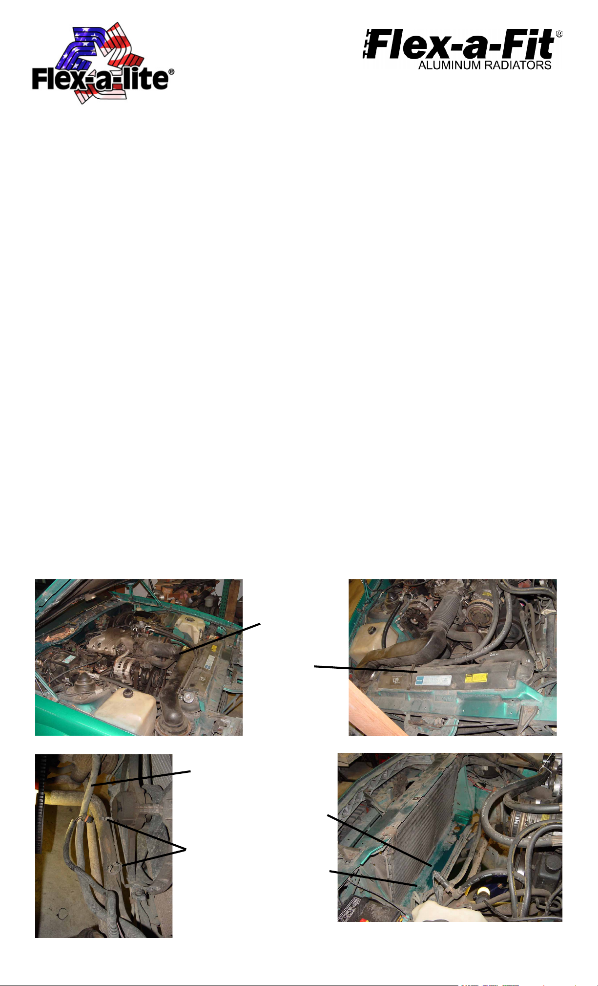
(Detail 1a)
Wire loom
Wire loom
mounts
Flexible air duct
Top radiator bracket
(Detail 1b)
Showing lower
cross member w/
radiator removed
Clean debris
from this space
(Detail 2)
(Detail 3)
Rev. 09-14-09 #99484 Page 1 of 5
Page 2

INSTALLATION OF NEW FAN AND SHROUD ASSEMBLY:
1. Start by removing the bottom rubber radiator mounts. Trim the rubber mounts flat across the top to
allow for the flat bottomed FAL radiator to sit flush on top of them. (see detail 4) Reinstall rubber
mounts, located back to original positions.
2. Gently lower the fan mounted radiator into engine compartment and place the radiator on top of the
rubber mounts. Note: Installing the radiator at this point will be complicated by power steering lines on
driver’s side. You may need to slightly modify location of lines to fit space with radiator side tank. Shift
radiator side to side until centered. (see detail 5)
3. Attach bracket pt. #56403 to radiator top but do not tighten. Aligning bracket slots to brass inserts and
use 2 ea. 5/8” long ¼-20 bolts and flat washers provided. (see detail 6)
4. Attach lower half of bracket #56403 to upper cross member reusing the bolts (2) saved from step #16
of the removal instructions but do not tighten yet.
5. Verify radiator base is nested inside lower cross member on top of rubber mounts then tighten all bolts
thru bracket #56403. The radiator should be secured at this point.
6. From below the vehicle, thru the lower frame cross member, reuse saved bolts (2) from step #13 of the
removal instructions and reinstall:
a. Power steering cooling lines.
b. Plastic bottom fan bracket and metal support bracket assembly. (see detail 7&8)
7. Reattach bottom radiator hose and replace hose into metal support bracket.
8. Reattach wire loom to mounts on metal support bracket.
9. Remove barbed hose fitting with 1/8” NPT thread from hardware kit and screw into radiator filler neck.
Attach overflow hose leading to coolant reservoir.
10. Reattach top radiator hose.
(Detail 4)
Trim line
(Detail 5)
Upper cross
member
Metal support
bracket
Plastic bottom
fan bracket
(Detail 6)
Bracket
#56403 shown
mounted
(Detail 7)
Rev. 09-14-09 #99484 Page 2 of 5
Page 3

11. Attach bracket #56404, on top of bracket #56403, on driver’s side. You will need to remove,
and then reinstall, a bolt previously installed in step #3. The top radiator hose is to be supported by this bracket. Note: Disregard bracket installation if your upper radiator hose is routed
in a way that can’t take advantage of the bracket. (see detail 9 &10)
12.Attach bracket #56405 on top of bracket #56403 and into upper cross frame on passenger’s
side. You will need to remove, and then reinstall a bolt previously installed in step #4. The “Z”
shaped air ducting is to be supported by this bracket. Note: Disregard bracket installation if
your intake manifold’s air ducting is routed in a way that can’t take advantage of the bracket.
(see detail 10)
13.Suggestions for securing A/C hoses to radiator bracket #56405:
a. If your intake manifold has the “Z” shaped air ducting, secure to underside of bracket
#56405 with zip ties. (not included)
b. If your intake manifolds air ducting doesn’t take advantage of bracket #56405, route the
A/C hoses atop the bracket and secure with zip ties. (not included)
14.Reattach flexible air duct to intake manifold. Be sure to also reattach integrated tube leading to
passengers side valve cover.
15.Reattach “Z” shaped air ducting between air filter canister and flexible air duct. Note: If your
vehicle comes equipped with a strait forward or other air ducting configuration, reattach it
instead.
16.Reattach negative (-) battery cable to battery.
17.Fill radiator/ cooling system with vehicle manufacture recommended coolant. Remember to fill
reservoir to “cold fill level” if needed.
18.Locate the temperature sensor in the kit bag. Insert the temperature sensor into the radiator
fins near the inlet. Leave ¼” or less protruding from the surface of the radiator for opti-
mum performance. The wires will run out through the top corner of the fan shroud. These will
be used later when wiring the VSC.
Note: BE SURE that all moving parts of the engine and electrical fan assembly are clear of
each other before proceeding!
(Detail 8)
Plastic/metal
bracket
assembly
Bracket
#56404 shown
mounted
Lower cross
member
(Detail 9)
Bracket
#56405 shown
mounted
(Detail 10)
Rev. 0-14-09 #99484 Page 3 of 5
Page 4

Fan Wiring Instructions
FOLLOW THESE INSTRUCTIONS CAREFULLY TO AVOID DAMAGING THE CONTROL UNIT,
FAN MOTORS, AND YOUR VEHICLE! WHEN CRIMPING WIRES, ALW AYS USE A QUALITY
CRIMPING TOOL (DO NOT USE PLIERS OR OTHER DEVICES).
Step 1: Locate mounting point for the VSC (variable speed control) unit
Locate a mounting point for the VSC near inlet side of the radiator. The control unit needs to be placed within
about 2-feet of radiator inlet hose. On the fender well next to the radiator may be a convenient location. Attach the control unit using the screws provided.
Step 2: Wire the fan motors (refer to Wiring Diagram, below)
Using the large yellow butt connectors provided, attach a length of the thick (10 AWG) red wire to the red motor
wires at fan. Attach a length of the thick (10 AWG) black wire to the black motor wires at the fan. Once the fan
is in place, these will attach to the control unit. If mounting the control somewhere in the engine compartment,
leave enough wire to reach the control unit.
WIRING DIA GRAM
NOTE: For pusher configuration, flip the fan blades over and reverse motor wire polarity
(black motor wire positive, red wire negative).
3. Connect the fan wires to the VSC
Now begin wiring the motors to the VSC. Using the yellow butt connectors provided, connect the red wire you
attached to the fan motor wires in Step 2 to the yellow wire on the VSC. Connect the black wire from the
motor wires to the purple wire on the VSC. (see wiring diagram) NOTE: Failure to do this will result in
incorrect operation and damage to fan motors!
4. Connect power leads
Determine the length needed to run thick red and black wire from the VSC to the battery terminals and trim
appropriately. Crimp a large yellow ring connector to one end of the each wire and connect the black wire to
the negative (-) battery terminal, but Do Not connect the red wire yet. Using butt connectors, connect the fuse
holder provided inline with the red wire. The fuse and fuse holder will protect the fan motors and your vehicle’s
electrical system from damage.
5. Ignition controlled power source
Locate fuse box. Find a circuit that is “hot “ when the key is in the “ON” position. NOTE: DO NOT use the
DRL or brake/taillight fuse! Attach the included fuse tap to fuse. Attach a female connector to the thin red
wire included and connect to the fuse tap. Trim the wire so that it will reach the VSC. Attach pink female
connector to end of wire and connect to terminal #9 on VSC.
6. Fan operation with air conditioning
Locate the wires coming from the A/C compressor. Determine which wire is ground and which is positive by
using a volt meter. Connect or splice the thin green wire to the positive (+) wire of the A/C compressor using
the blue “Piggy-Back” connector. Determine length needed to reach VSC and trim to length. Attach a pink
female connector to the wire. If the A/C compressor is activated by a positive (+) signal, connect this wire to
terminal #8 on VSC. If it is activated by a negative signal, connect to terminal #7 on VSC.
7. Temperature sensor
Locate the temperature sensor. Gently push probe through fins in radiator as close to the upper radiator hose
as possible, leaving about ¼” of the probe protruding out of the core. Place small black cap over exposed end
of probe seen through fins. Determine the length of wire needed to reach the VSC. IMPORTANT: Strip the
insulation back about 1" and fold the wire onto itself to effectively double the thickness of the wire before
connecting the pink female connectors as shown in at right. Attach these wires to terminals #10 & 11 on the
VSC. Both wires need to be connected but it doesn’t matter which wire goes to each terminal.
Rev. 09-14-09 #99484 Page 4 of 5
Page 5

8. Manual Switch
If manual switches (Flex-a-lite #31148) have been purchased, attach them as follows: To override
engine temperature signal and turn fans off, connect the switch to terminal #5 on VSC to send a
negative (-) signal. To override engine temperature signal and turn fans on, connect the switch to
terminal #6 on the VSC so that a negative (-) signal is sent.
The Variable Speed Control has new features.
At the set temperature, the fans will come on at 60%; this reduces the load on your charging
system. If the temperature rises, the fan speed will increase. If your set temperature is 195°F, then
between 195° and 205° the fan speed will increase from 60% to 100%. So after a 10-degree rise from
the set point, the fans will be running at 100%.
Initial Start-up and Adjustment Procedure
1. Turn ignition on. After 6 seconds, LED #L4 should light up (Refer to wiring connections diagram). If
not, check to make sure that there is 12 Volts at terminal #9 on VSC. The delay is to allow
starter to start the vehicle without the fans drawing any power.
2. With your engine running, engage the A/C. The fans should come on and cycle with the A/C compressor.
LED’s #L1, L3 and L4 should be lit when fans are running. If they do not turn on, verify that the A/C clutch
is engaged and make sure you have a positive signal when the clutch is engaged at terminal #8 on the
VSC. Shut off A/C and let engine continue to idle, or drive the vehicle a short distance to bring the engine
to operating temperature (IMPORTANT: You must monitor the vehicles temperature gauge).
3. Verify that operating temperature has been reached by feeling the upper radiator hose. Hot water should
be flowing through hose into the radiator. If the fans have not cycled on yet, slowly adjust the screw on the
VSC until the fans cycle on. Turning the screw further in this direction will keep the engine at a lower
temperature, and turning in the opposite direction will keep the engine at a higher temperature. (See VSC
Diagram) NOTE: THE TOTAL MOVEMENT OF THE ADJUSTMENT SCREW IS ABOUT ¾ OF A TURN.
TURNING THE SCREW BEYOND THE LIMITS WILL DAMAGE THE UNIT! Once desired temperature is
set, let the engine continue to idle and make sure the fans will cycle to maintain desired temperature.
When fans are running, LED’s #L1 and L4 should be lit.
Diagram of VSC adjustment screw
The Flex-a-lite Limited Warranty
Flex-a-lite Consolidated, 7213-45th St. Ct. E. Fife, WA 98424, Telephone No. 253-922-2700, warrants to the original purchasing user, that all Flex-a-lite
products to be free of defects in material and workmanship for a period of 365 days (1 year) from date of purchase. Flex-a-lite products failing within
365 days (1 year) from date of purchase may be returned to the factory through the point of purchase, transportation charges prepaid. If, on inspection,
cause of failure is determined to be defective material or workmanship and not by misuse, accidental or improper installation, Flex-a-lite will repl ace the
product free of charge, transportation prepaid. Flex-a-lite will not be liable for incidental, progressive or consequential damages. Some states do
not allow the exclusion or limitation of incidental or consequential damages, so the above limitation or exclusion may not apply to you. This warranty
gives you specific legal rights and you may have other rights, which vary from state to state. The Flex-a-lite warranty in in compliance with the
Magnuson-Moss Warranty Act of 1975.
Rev. 09-14-09 #99484 Page 5 of 5
 Loading...