

Page 1
6. Install and securely clamp the bottom “outlet” radiator
98388 Rev. 01-22-14
hose.
7. Install and securely clamp the top “inlet” radiator hose.
8. Mount overow bottle into fan shroud and attach hose.
9. Reattach negative (-) battery cable from battery.
10. Reassemble vehicle panels, LEAVING STOCK
RADIATOR COVER PANELS OFF.
11. Rell radiator with coolant, and optionally Flex-a-Chill
to protect your new radiator from corrosion.
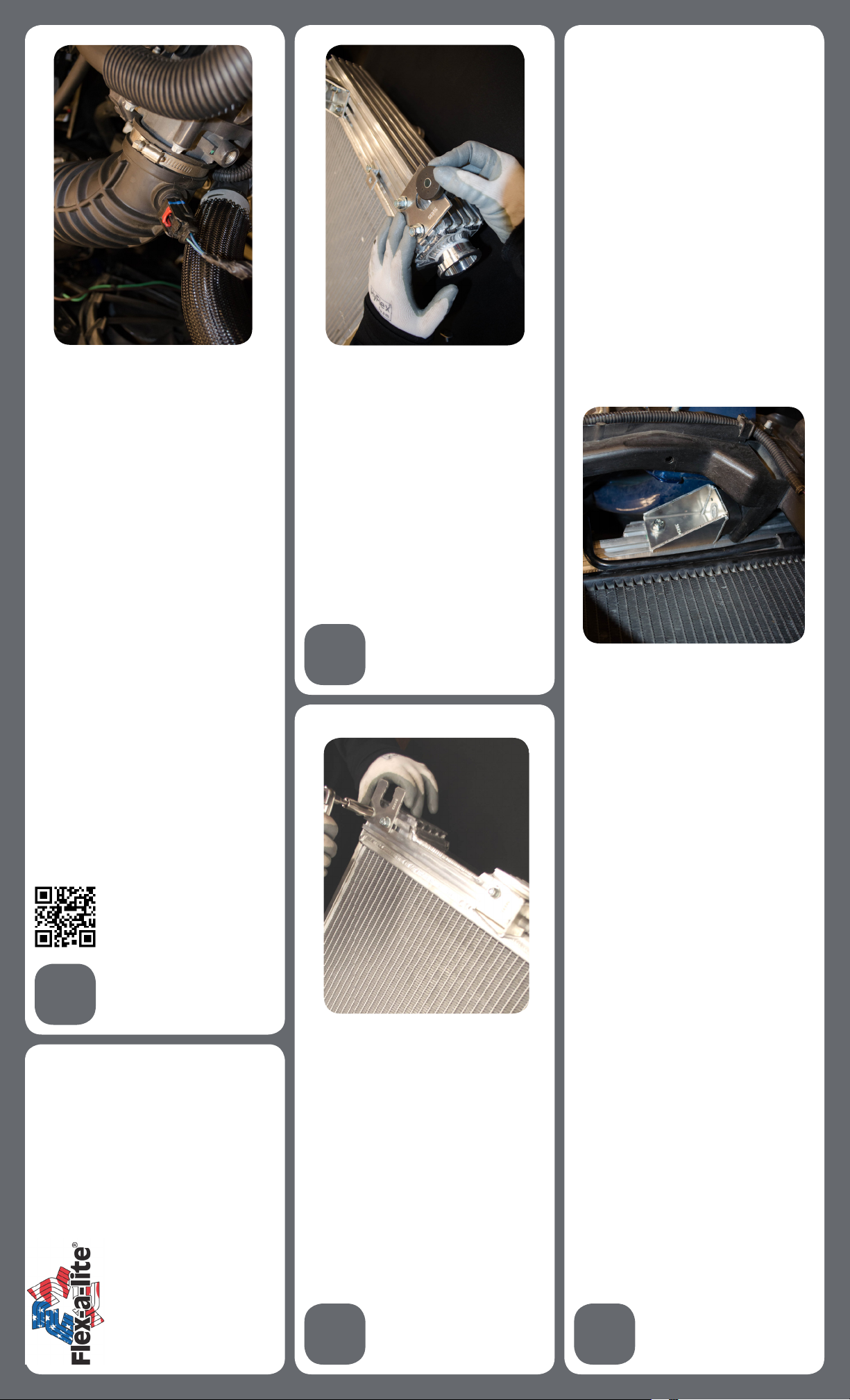
6. Loosen clamp at throttle body and remove sensor
Scan here with your smartphone to see a step-by-step install video
or type http://youtu.be/kMWHsM_WRFs into your favorite browser
1
Remove Stock Fan and Shroud Assembly
1. Make sure engine is cool.
from intake hose. Remove airbox, top radiator hose, and
overow bottle.
2. Disconnect negative (-) battery cable from battery.
7. Turn drainplug at front passenger side in grille and
drain. Remove bottom hose and push hose down to nish
3. Remove 6 pop-clips on top of grille, twist turn signal
bulbs and remove, and pop bottom clips from core
drain.
support to remove grille.
8. Remove ve bolts holding AC condenser to
radiator. (4 on front of radiator, 1 on drivers side)
9.Unplug fan harness, detach tree harness on passenger
side, remove bolts at top of radiator, and remove radiator.
4.Remove 2 phillips screws from bumper cover plate and
remove panel.
5. Remove tree clips holding top and botom radiator
cover. (4 on top, 3 on bottom, 2 on bottom sides of
radiator)
3
Transfer Radiator Mounts
1. Remove the factory rubber mounts on the bottom
radiator posts as well as the top slotted holes.
2. Place factory rubber mounts into supplied radiator
brackets.
2. Mount top brackets to vehicle using stock hardware.
3. Verify hood clearance of radiator. If there are any
interferences, loosen brackets and adjust where
necessary.
4. Slide t-bolts into corresponding track on the driver’s
side end tank to line up with the remaining bracket
#30894. Tighten bottom bracket mounting hardware on
both sides. The radiator should be secured at this point.
5. Attach AC condenser to end tanks using the supplied
brackets and t-bolts. (Only the 4 mounts on the front of
the core will be attached to the radiator)
#52308 Jeep Radiator Wrangler JK
#52309 Jeep Radiator Wrangler JK Hemi Swap
#52388 Jeep Radiator/Fan Wrangler JK
#52389 Jeep Radiator/Fan Wrangler JK Hemi
Fits MOST Jeep Wranglers, 2007-2013
(Note: Automatic transmissions may require an
auxiliary transmission oil cooler. Vehicle models may
vary; review the instructions and components for
compatibility with your vehicle prior to installation.)
2
Assemble Flex-a-Fit® Radiator
1. Attach both brackets #30893 ush with top of radiator
4
tank with 1 each t-bolt, washer, and nylock per slot.
2. Loosely attach bracket #30894 ~5-3/4” up from bottom
of radiator on PASSENGER SIDE ONLY with 1 each t-bolt,
washer, and nylock per slot.
IF INSTALLING RADIATOR ONLY KIT: Remove your
factory fan shroud and align to top edge. Attach bracket
#30895 to end tanks using 1 each t-bolt, washer, and
nylock. Position so bracket locks into fan shroud mating
tab and attach top shroud tabs with t-bolt hardware.
Install New Flex-a-Fit® Radiator
NOTE: For Hemi Motorswap Applications: A
minimum clearance of 7-7/8 inch from the vehicle
core support to the engine is needed to t the
radiator/fan combo. Some modication may be
needed.
1. Gently lower the radiator or radiator/fan combo into
the engine compartment and place the lower post on
passenger side bracket #30894 into the factory mount,
making sure the top brackets line up with the factory core
support mounting holes.
Page 2

Connect Power Leads
1. Determine the length needed to run thick red and
black wire from the VSC to the battery terminals and trim
appropriately.
2. Crimp a large yellow ring connector to one end of each
wire and connect the black wire to the negative (-)
battery terminal, but DO NOT connect the red wire yet!
3. Using butt connectors, connect the fuse holder
provided inline with the red wire.
The Flex-a-lite Limited Warranty
Flex-a-lite Consolidated, 7213-45th St. Ct. E. Fife, WA 98424, Telephone
No. 253-922-2700, warrants to the original purchasing user, that all
Flex-a-lite products to be free of defects in material and workmanship for
98275 Rev. 01-22-14
a period of 365 days (1 year) from date of purchase. Flex-a-lite products
failing within 365 days (1 year) from date of purchase may be returned to
the factory through the point of purchase, transportation charges
prepaid. If, on inspection, cause of failure is determined to be defective
material or workmanship and not by misuse, accidental or improper
installation, Flex-a-lite will replace the fan free of charge, transportation
prepaid. Flex-a-lite will not be liable for incidental, progressive or
consequential damages. Some states do not allow the exclusion or
limitation of incidental or consequential damages, so the above
limitation or exclusion may not apply to you. This warranty gives you
specic legal rights and you may have other rights, which vary from state
to state. The Flex-a-lite warranty is in compliance with the
Magnuson-Moss Warranty Act of 1975.
7 8
6
Controller Wiring
1. Using the large yellow butt connectors provided, attach
a length of the thick (10 AWG) red wire to the orange
motor wires at the fan.
2. Attach a length of the thick (10 AWG) black wire to
the black motor wires at the fan. Once the fan is in place,
VSC Mounting
1. locate a mounting point for the VSC near inlet of the
radiator. The control unit needs to be placed within
2-feet of radiator inlet hose for temp. probe placement.
On the fender well next to the radiator may be a conve-
nient location.
these will attach to the control unit.
orange
2. Attach the control unit using the screws provided.
11
What’s Next?
3. Turn A/C o. Let vehicle warm up to normal operating
Register your product for warranty at
temperature. Adjust screw terminal clockwise to increase
turn-on temperature and counter-clockwise to decrease
http://automotive.ex-a-lite.com/warranty-registration/
temperature. NOTE: THE SCREW TERMINAL ONLY
ROTATES 3/4 OF A TURN. IF TURNED BEYOND ITS
Enjoy your Flex-a-lite performance cooling product!
If you need further assistance, please contact tech services
at 253-922-2700 M-F 8:00am-5:00pm PST.
LIMITS THE TERMINAL WILL BREAK!
4. Once desired temperature is set, let the engine idle
and make sure the fan cycles to maintain desired
temperature. Make sure the fan is pulling air through
the radiator toward the engine.
5. Reassemble vehicle top o coolant.
5
Fan Wiring Instructions
FOLLOW THESE INSTRUCTIONS CAREFULLY TO AVOID
DAMAGING THE CONTROL UNIT, FAN MOTORS AND
YOUR VEHICLE! WHEN CRIMPING WIRES, ALWAYS USE A
QUALITY CRIMPING TOOL (DO NOT USE PLIERS OR
OTHER DEVICES).
9
NOTE:DO NOT use the DRL or brake/taillight fuse!
Reassemble And Test
1. Insert temp. probe near inlet hose, leaving 1/4” of the
probe sticking out from the core. Be careful not to
damage radiator core.
2. Turn Ignition on. If the LED farthest from VSC power
wires does not turn on after 6 seconds, check 12V power
going to terminal #9.
3. With engine running, turn A/C on. The fan should be
running and 3 of the LEDs should be lit. If not, verify A/C
clutch is engaged and correct signal wire is triggered.
Ignition-controlled Power Source
10
1. Locate the fuse box.
2. Find a circuit that is hot when the key is in the ON
position.
3. Attach the included fuse tap to the fuse. Attach a fe-
male connector to the thin red wire included and connect
to the fuse tap.
4. Attach pink female connector to end of the wire and
connect to terminal #9 on VSC.
 Loading...