

Page 1

Mustang Radiator and Fan Combo #52185
or Mustang Radiator #52100
Fits 1979-1993 Mustang 5.0L
INSTALLATION INSTRUCTIONS
Removal of the original radiator and fan:
1. BE SURE THE ENGINE IS COOL BEFORE PROCEEDING!!
2. FOR YOUR SAFETY, disconnect the
negative battery cable before proceeding
with the installation.
3. Utilizing the drain plug on the
passenger’s side of the radiator, start
draining the coolant. It may be necessary to
remove the radiator cap to release the
vacuum inside the radiator for better
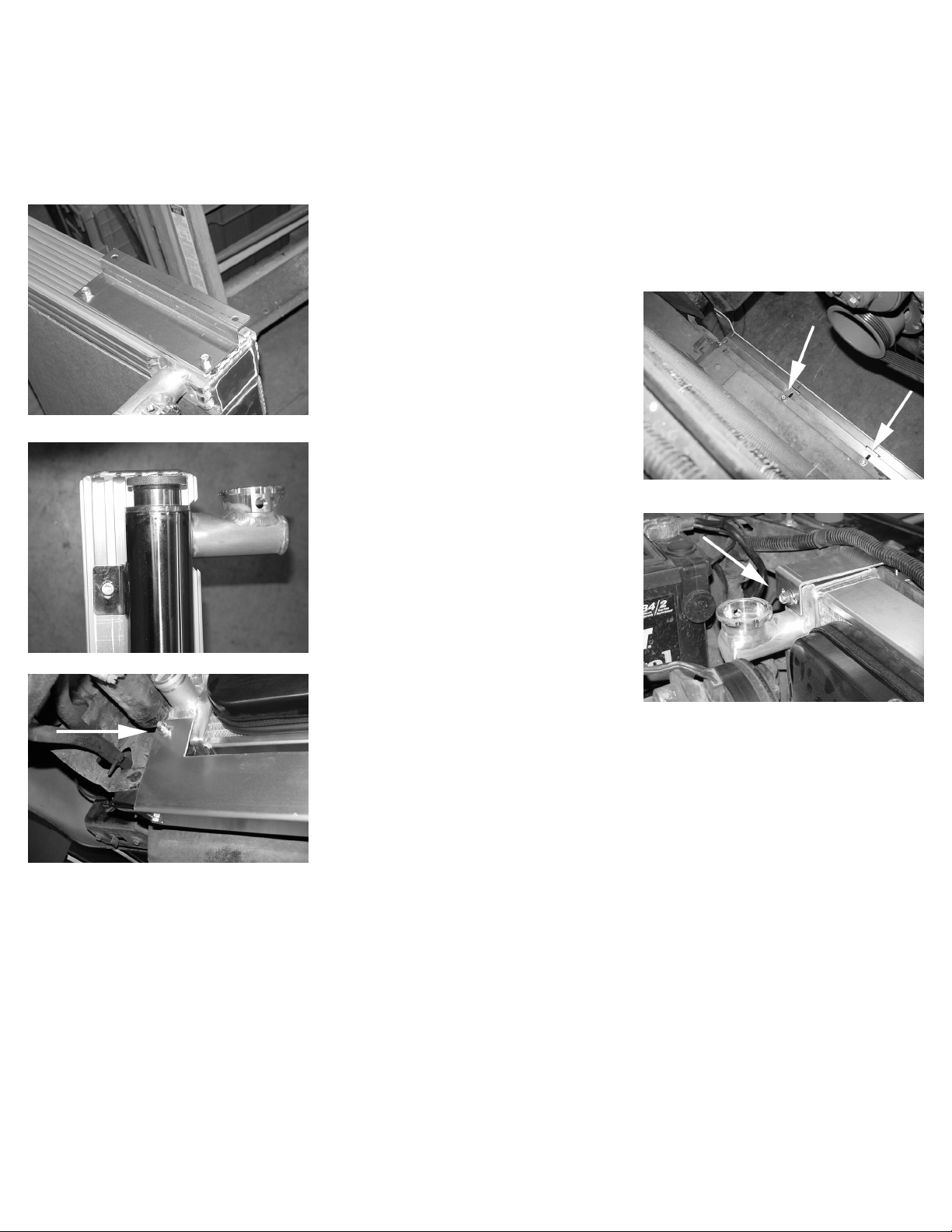
Detail 2
Detail 4
Detail 6
check the clearance of these bolts on the backside of the pulley to the water
pump. After tightened, there should be no less than 1/4” of clearance to the
water pump. If they are too close, they may cause severe damage to the water pump upon start-up. It may be
necessary to replace these bolts with shorter ones (refer to detail 4).
draining (see detail 1).
4. If equipped, remove the sensor wire
from the lid of the overflow bottle (see
detail 2).
5. Disconnect the overflow bottle hose
from the radiator.
6. Remove the two (2) bolts and clips from
the top of the factory shroud. (see detail 3)
7. Remove the four (4) bolts holding the
fan to the water pump pulley with a 1/2”
open-end wrench. Note: Save these bolts to
be used later (see detail 4).
8. Lift the original shroud and fan out of
the vehicle at the same time. If your vehicle is equipped with an overflow bottle
attached to the shroud, it is not necessary
to remove the overflow bottle separately.
9. Note:If replacing Radiator only, reatach
fan to water pump. Replace the four (4)
bolts that held the fan to the water pump
with a 1/2” socket or wrench. Be sure to
Detail 1
Detail 3
Detail 5
rev. 02-26-09 #54993 Page 1 of 4
Page 2
Removal of the original radiator and fan cont’d.
10. Remove the upper and lower hoses of the radiator. It is not necessary to remove them completely from the vehicle
for installation. (see detail 5 on page 1).
11. Using a 1/2” socket or wrench, remove the two (2) brackets that hold the original radiator in place at the top. Note:
Save these bolts to be used later. (see detail 6 on page 1)
12. Remove the original radiator by lifting it straight up. Note: Use caution while removing the radiator, it may still
contain coolant which can spill out.
Installation of Radiator and Fan Combo
#52185 or Radiator only #52100
1. Find the new radiator overflow bottle
and mounting bracket. Mount the bracket
(#51107) to the radiator on the filler side as
shown in detail 7. Now mount the overflow
tank to the bracket with the fasteners
provided with the overflow bottle as shown
Detail 7
Detail 8
Detail 10
between the overflow bottle and the battery. Place the radiator as far forward, or away from the engine, as possible to
allow enough clearance between the fan and the water pump. Note: Every vehicle may vary, some adjustments may need
to be made for a better fit.
6. Using two (2) each of t-studs and nuts, fasten the lower bracket to the bottom of the radiator. Push the radiator toward
the front of the car, away from the engine. Tighten all of the fastners on the lower bracket (see detail 10).
7. Install the two (2) upper brackets (#51104) with the original bolts from the original top brackets. Using 2ea. t-studs
and locknuts, fasten the brackets to the top of the radiator utilizing the channels in the radiator side tank. Pull the radiator
toward you (away from the engine) as you tighten the fasteners for maximum clearance between the fan and the engine
(see detail 11).
8. Install the pipe-nipple for the overflow tube to the filler neck of the radiator. Route and trim the overflow hose as
needed. Note: Be sure that there is enough clearance of the hose to any moving engine components.
9. Connect the upper and lower radiator hoses to the radiator. Make sure they are properly clamped to the inlet and outlet
tubes. Note: BE SURE that all moving parts of the engine and electric fan are clear of each other before proceeding!!
in detail 8. Note: DO NOT allow the filler
cap of the overflow bottle to exceed the
height of the top of the radiator for clearance (see detail 7 and 8).
2. Attach the hose to the “short” tube on the
bottom of the overflow tank. Use a hose
clamp to hold it in place. DO NOT connect
the hose to the radiator yet. Note: The
longer tube on the bottom of the overflow
tank is a breather tube, DO NOT obstruct
or remove it.
3. Mount the large lower bracket (#51105)
to the lower edge of the core support with
the four (4) bolts, four (4) washers and four
(4) lock nuts. DO NOT secure the bracket completely. There should be enough
movement for adjustment to the bracket later (see detail 9).
4. Flare or bend the lower orginal radiator mounts towards the engine slightly to
make enough room for the new radiator to rest in the lower mounts. This may
require the use of pliers. DO NOT remove the rubber in the mount, it will provide
a cushion for the new radiator.
5. Lower the radiator into the vehicle. Be sure that there is enough clearance
rev. 02-26-09 #54993 Page 2 of 4
Detail 9
Detail 11
Page 3
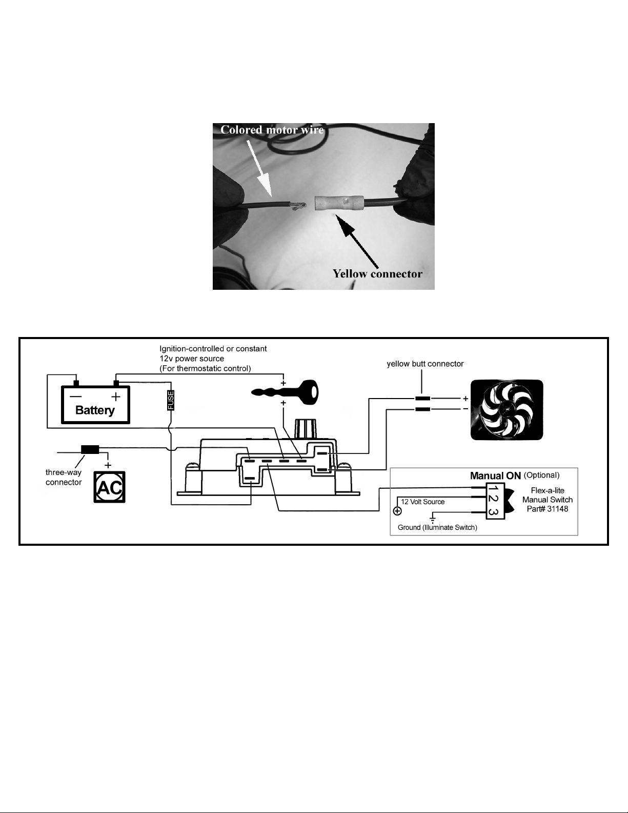
Wiring the Fan: Radiator and Fan Combo #52185 only
1. Using the yellow butt connectors provided, attach the large diameter wire (10 AWG) RED wire to the COLORED
motor wire. Attach the large diameter (10 AWG) BLACK wire to the BLACK motor wire. Note: Strip an additional 1/
8” from the motor wire insulation and fold them over to increase the thickness of the wire where it will slide into the
butt connector (see diagram below).
2. Mount the control module inside the engine compartment. The fan shroud can be used for mounting the control
module. Note: Anywhere the control module is mounted MUST be clear of moving components.
Colored
Black
Green
Thick Black
Thick Red
Thick Red
Thick
Black
3. Connect the motor wires to the control module. The RED wire (10 AWG) to the “M+” terminal and the BLACK wire
(10 AWG) to the “M-” terminal.
4. Use the large diameter (10 AWG) RED wire to run power directly from the battery (+) terminal to the “B” terminal
on the control module. Connect the fuse holder in-line with this wire, as shown, but do not insert the fuse yet. Use the
YELLOW female, ring and butt connectors provided.
5. Use the large diameter BLACK (10 AWG) wire to run from the negative (-) battery terminal to the “G” terminal on
the control module. Use the YELLOW female connector and ring connector provided.
6. Use the small diameter RED (14 AWG) wire to connect the “+” terminal on the control module to a positive (+)
power source. Note: Attaching this wire to an ignition-controlled source will shut off the fan when the engine is turned
off. Attach this wire to an uninterrupted (always hot) power source to allow the fan to continue running after the engine
is shut off. Use the BLUE female connector and fuse taps (included) if necessary.
Wiring instructions are continued on page 4
rev. 02-26-09 #54993 Page 3 of 4
Page 4

Wiring the Fan Continued:
7. (OPTIONAL) For air conditioning control, if desired, connect the “C” terminal on the control module to the positive
(+) wire that triggers the A/C compressor using the small diameter GREEN (14 AWG) wire. Using a voltmeter, determine which wire coming from the compressor is the positive (+) wire trigger wire. Use the 3-way BLUE connector
(included) to tap into this wire and send a signal to the fan control module. The fan will cycle on and off with the A/C
clutch when the A/C is turned on.
8. (OPTIONAL) For manual switch operation, use Flex-a-lite p/n 31148. Connect the switch as shown on the wiring
diagram. Connect the “M” terminal on the control module to the “1” terminal on the switch. Connect the “2” terminal
on the switch to a positive (+) 12-Volt power source. Connect terminal “3” on the switch to a good ground (for switch
illumination). Note: To prevent thermostatic activation, if only manual switch operation is desired, omit the lead to the
(+) terminal of the control box. “B”, “G”, “M+” and “M-” must remain connected. If not using a Flex-a-lite manual
switch, DO NOT CONNECT a ground wire to the switch!
9. Locate the inlet hose from the engine to the radiator. Insert the probe through the radiator fins near the inlet hose.
Install the black insulator cap on the back side of the radiator, this will help hold the probe in place.
10. If you disconnected any hoses or drained coolant to install the fan, reconnect ALL of the hoses and refill the radia-
Install the temperature probe near the inlet hose... then replace the insulator cap.
tor. Press the control knob (included in the wiring kit) onto the control box shaft. Turn the knob clockwise until it stops.
Reconnect the battery and start the engine and allow it to idle. Using a hand-held thermometer (positioned near the inlet
hose) or the vehicles temperature gauge, monitor the temperature. When the coolant temperature is slightly above
normal or desired temperature, turn the knob counter-clockwise just until the fan turns on. From now on, the fan should
activate at this temperature setting. Adjust as necessary to maintain desired temperature.
Want to upgrate your clutch fan to a more fuel efficient
Flex-a-lite electrical fan?..(if installing part # 52100 only)
If you are installing the Flex-a-lite Mustang Radiator #52100 only, you may want to consider replacing your belt
driven clutch fan for up to 10% fuel savings plus more horsepower by upgrading to the same electrical fan used in our
Mustang Radiator and Fan combo kit Pt. #52185.
The two components you will need to order are Pt.#180 (Electric Fan Kit) and Pt.#52180K (Mounting Bracket kit)
The Flex-a-lite Limited Warranty
Flex-a-lite Consolidated, 7213-45th St. Ct. E. Fife, WA 98424, Telephone No. 253-922-2700, warrants to the original purchasing user, that all Flex-a-lite products to be free
of defects in material and workmanship for a period of 365 days (1 year) from date of purchase. Flex-a-lite products failing within 365 days (1 year) from date of purchase
may be returned to the factory through the point of purchase, transportation charges prepaid. If, on inspection, cause of failure is determined to be defective material or
workmanship and not by misuse, accidental or improper installation, Flex-a-lite will replace the product free of charge, transportation prepaid. Flex-a-lite will not be liable
for incidental, progressive or consequential damages. Some states do not allow the exclusion or limitation of incidental or consequential damages, so the above limitation
or exclusion may not apply to you. This warranty gives you specific legal rights and you may have other rights, which vary from state to state. The Flex-a-lite warranty in in
compliance with the Magnuson-Moss Warranty Act of 1975.
rev. 02-26-09 #54993 Page 4 of 4
 Loading...