

Page 1

Camaro Radiator & Fan Kit #52187
or Camaro Radiator Kit #52007
Fits 1967-1969 “First Generation” Chevrolet Camaro
Notes: Measure for clearances prior to installation. May not be suitable within certain Big Block /
long water pump engine configurations.
Manual transmission preferred; automatic transmission requires a remote cooler.
INSTALLATION INSTRUCTIONS
Remove Existing Fan, Shroud & Radiator
BE SURE THE ENGINE IS COOL BEFORE PROCEEDING!!
1.
Disconnect the negative (-) battery cable before proceeding with
2.
the installation.
Utilizing the drain plug on the drivers side of the radiator, start
3.
draining the coolant.
the radiator cap to release the vacuum inside the radiator for better
draining.
Loosen, but do not remove, the four (4) bolts holding the fan to the
4.
water pump.
Remove the screw securing top of fan shroud to bracket centered
5.
above the radiator.
Remove the upper and lower hoses from the radiator. It is not
6.
necessary to remove them completely from the vehicle for
installation.
see Detail 1 It may be necessary to remove
see Detail 2
Detail 1
Detail 2
Drain plug
Shroud Mounting Bracket
Remove fan belt by loosening top and bottom bolts of the alternator
7.
bracket, then pivot alternator toward the water pump to relieve belt
tension.
Remove the four (4) bolts holding the fan to the water pump pulley.
8.
Note: Save these bolts to be used later. Lift the original shroud and
fan out of the vehicle at the same time.
Remove shroud mounting bracket centered above radiator.
9.
see Detail 2
If vehicle is equipped with an automatic transmission, remove both
10.
inlet and outlet lines from passenger side of radiator.
see Detail 3
Remove bolts securing radiator to vehicle on both driver and pas
11.
senger side. Note: you may need to remove battery and battery tray
to gain access to mounting bolts on passenger side. Save mounting
bolts removed from passenger side. You will be reusing these bolts
later.
Remove the original radiator by lifting it straight up. Note: Use cau-
12.
tion while removing the radiator, it may still contain coolant which
can spill out.
Detail 3
Disconnect
transmission
lines
-
Installation instructions continued on next page
Rev. 02-09-11 99187 Page 1 of 4
Page 2

Installation of Radiator and Fan Combo #52187
or Radiator only #52007
Utilizing the included T-nuts (4 ea.), washers (4 ea.), and Lock nuts (4 ea.), mount bracket #51871 to the
1.
Driver’s side of the radiator; (studs should be pointing towards the front of the vehicle) and bracket #51872
to the Passenger’s side of the radiator. (the large cut out should
be toward battery) see Detail 4
Once the brackets are attached, you will need to lower the ra
2.
diator into the engine compartment. It is easiest if you feed the
studs of Driver’s side bracket into the stock mounting points on
the front radiator support, then loosely secure with supplied 1”
fender washers and locknuts but do not tighten locknuts yet.
Using the stock bolts (3 ea.) you removed earlier during step
3.
#11 of the “Removal” process, loosely secure the Passenger’s
side radiator bracket to the stock mounting points on the radiator
support.
Flex-a-Fit® radiator tanks are made for maximum adjustability.
4.
Depending on space limitations within your engine compartment,
you will need to adjust bracket positioning by sliding the T-nuts
up / down or even select an alternate tank slot. Be sure all bracket mounting hardware has been sufficiently
tightened after proper positioning has been achieved.
Detail 4
Bracket #51872
Bracket #51871
Attach the
brackets as
shown above
Resecure the pulley to the water pump, using the four (4) bolts that held the fan to the water pump, then re
5.
install fan belt. If you’re replacing the radiator only, reattach the fan to water pump. Note: Be sure to check
the clearance of these bolts on the backside of the pulley to the water pump. After tightened, there
should be no less than ¼” of clearance to the water pump. If they are too close, they may cause severe
damage to the water pump upon start-up. It may be necessary to replace these bolts with shorter ones.
Install the pipe-nipple for the overflow tube to the filler neck of the radiator. Route and trim the overflow hose
6.
as needed. Note: Be sure that there is enough clearance of the hose to any moving engine components.
Connect the upper and lower radiator hoses to the radiator. Make sure they are properly clamped to the
7.
inlet and outlet tubes. Note: BE SURE that all moving parts of the engine and electric fan are clear of each
other before proceeding!!
Fill radiator/ cooling system with vehicle manufacture recommended coolant. Remember to fill reservoir to
8.
cold fill level if equiped.
Note: For automatic transmission equipped cars.
We chose not to install a transmission cooler within our radiator’s side tank. This maximizes the cooling efficiency
of both your engine and transmission. If you do have an automatic transmission, you will need to install an
aftermarket transmission cooler. Flex-a-lite makes a full line of transmission coolers along with customized
mounting options. The following FAL components are recommended to address your ’67 – 69” Camaro’s
transmission cooling needs.
FAL transmission cooler: pt. # 4116
•
FAL Accessory Bracket set: pt. #32122
•
FAL “GatorClips®” set: pt. #3909
•
For more mounting options, call Customer Assistance at: 1-877-767-0554 or FAX: (253) 922-0226.
#52187 with recomended
transmission cooler and
mounting hardware
Exploded view of Accessory
Bracket set: pt. # 32122
Rev. 02-09-11 99187 Page 2 of 4
Page 3
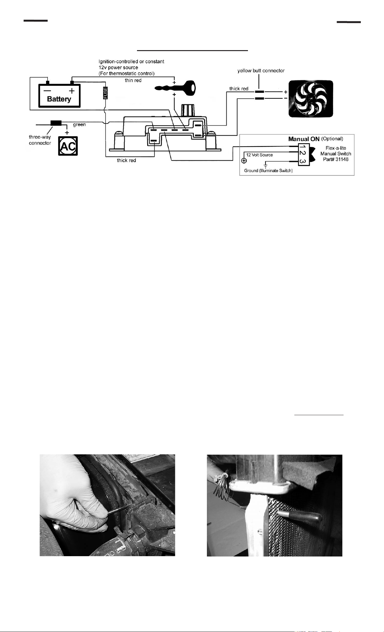
Wiring the Fan: Radiator and Fan Combo #52187 only
Wiring Diagram
colored
thick black
Connect the motor wires to the control module (Red wire to the “M+” terminal and black wire to the “M-”
1.
terminal).
Use the large diameter red (10 AWG) wire to run power directly from the battery positive (+) terminal to
2.
the “B” terminal on the control module. Connect the fuse holder in-line with this wire, as shown, but do not
insert the fuse yet. Use the yellow female, ring, and butt connectors provided.
Use the large diameter black (10 AWG) wire to run from the negative (-) battery terminal to the “G” terminal
3.
on the control module. Use the yellow female connector and ring connector provided.
Use the small diameter red wire (14 AWG) to connect the “+” terminal on the control module to a positive
4.
power source. NOTE: Attaching this wire to an ignition-controlled source will shut off the fan when
the engine is turned off. Attach this wire to an uninterrupted (always hot) power source to allow the fan
to continue running after th e engine is shut off. Use the blue female connector and fuse taps (included) if
necessary.
thick
black
black
If the vehicle is equipped with air conditioning, a mandatory connection is needed between the “C” terminal
5.
on the control module and the positive wire that triggers the A/C compressor. Using a voltmeter, determine
which wire coming from the compressor is the positive trigger wire. Use the included 3-way connector and
small diameter green wire (14 AWG) to tap into this wire and send a signal to the fan control module. The
fan will cycle on and off with the A/C clutch when the A/C is turned on.
(Optional) For manual switch operation, use Flex-a-lite p/n 31148. Connect the switch as shown on the
6.
wiring diagram (previous page). Connect the “M” terminal on the control module to the “1” terminal on the
switch. Connect the “2” terminal on the switch to a positive 12v power source. Connect terminal “3” on
the switch to a good ground (for switch illumination). NOTE: To prevent thermostatic activation (if only
manual switch operation is desired), omit the lead to the “+” terminal of the control box. “B”, “G”,
“M+” and “M-” must remain connected. If not using a Flex-a-lite manual switch,
ground wire to the switch!
Use the zip ties provided to secure the wires and prevent them from interfering with fan blades, belts, and
7.
pulleys in the engine compartment. Insert the fuse provided.
do not connect a
Install temp. probe near inlet hose...
Locate the inlet hose from the engine to the radiator. Remove the black insulator cap from the temperature
8.
probe then insert the temp. probe through the radiator fins near the inlet hose. Reinstall the black insulator
cap.
then replace the insulator cap.
Rev. 02-09-11 99187 Page 3 of 4
Page 4

Press the control knob (included in wiring kit) onto the control box shaft. Turn the knob clockwise until it
9.
stops.
Reconnect negative (-) battery cable to battery. Start the engine and allow it to idle. Using a hand held
10.
thermometer (positioned near the inlet hose) or the vehicle’s temperature gauge, monitor the temperature.
When the coolant temp is slightly above normal (or desired temp.), turn the knob counter-clockwise just
until the fan turns on. From now on, the fan should activate at this temperature setting. Adjust as necessary
to maintain desired temperature.
Troubleshooting the #180 electric fan
Problem Possible Cause How to find out Solution
Fan does not turn
on regardless of
temperature
Fan still does not turn
on
Fan still does not turn
on
Fan does not come on
until the temperature
is very hot
“+” terminal on control
box not connected to
proper source
Fuse to battery
positive post blown.
Wires to terminals “B”
and “G” aren’t properly
hooked up.
Motor wired
improperly
Temp. probe not
located in optimum
position
Trace wire connected
to the “+” terminal.
Use a voltmeter or
test light to check for
voltage.
Inspect the fuse in the
holder.
Check for power and
ground through lines
hooked to terminals
“B” & “G”.
Check to see that the
blue motor wire runs
to the “M+” terminal
and the black motor
wire runs to the “M-“
terminal on the control
box.
Check location of
temp. probe.
If there is no power to
the “+” terminal, find
an ignition-switched or
constant 12v. power
source and wire it to
the “+” terminal on the
control box.
Replace fuse.
Hook up wires for
terminals “B” & “G” to
battery and ground
respectively.
Connect wires to
correct terminals.
If motor does not spin
after checking wiring,
call tech support at
1-800-851-1510.
Temp. probe should
be located nearest the
upper radiator hose.
Fan was working
properly but suddenly
shut down
When engine is
started, fan comes on
even though engine
is cold
Temperature set to
high
Usage of a chassis
ground and/or
alternate source for
power other than
positive terminal on
battery
Constant (always
“hot”) 12v source
hooked to “C” terminal
A/C or defrost turned
on
Locate temperature
adjusting knob on top
cover of control box
Trace wire from
terminals “B” and “G”
to find source.
Trace the wire
connected to the “C”
terminal and make
sure it is spliced into
the positive trigger
wire from the A/C
compressor clutch.
Check if defrost
activates a/c or if the
a/c is on.
Turn knob counterclockwise to set the
control box to a lower
temperature.
Move to posts on the
battery.
Splice into the positive
trigger wire to the A/C
clutch and connect
to the “C” terminal on
control box.
Shut off a/c or leave
on as this is normal
operation.
99993-Z
The Flex-a-lite Limited Warranty
Flex-a-lite Consolidated, 7009-45th St. Ct. E. Fife, WA 98424, Telephone No. 253-922-2700, warrants to the original purchasing user, that all Flex-a-lite
products to be free of defects in material and workmanship for a period of 365 days (1 year) from date of purchase. Flex-a-lite products failing within
365 days (1 year) from date of purchase may be returned to the factory through the point of purchase, transportation charges prepaid. If, on inspection,
cause of failure is determined to be defective material or workmanship and not by misuse, accidental or improper installation, Flex-a-lite will replace the
product free of charge, transportation prepaid. Flex-a-lite will not be liable for incidental, progressive or consequential damages. Some states do
not allow the exclusion or limitaion of incidental or consequential damages, so the above limitation or exclusion may not apply to you. This warranty gives
you specific legal rights and you may have other rights, which vary from state to state. The Flex-a-lite warranty is in compliance with the Magnuson-Moss
Warranty Act of 1975.
Rev. 02-09-11 99187 Page 4 of 4
 Loading...