

Page 1
Part# 475 JEEP WRANGLER FAN II (Nylon Shroud)
INST ALLA TION INSTRUCTIONS
1987-2003 4 & 6 cylinder Wranglers
NOTE: 1997 AND UP Wranglers were produced with one or more fluid tanks mounted directly to the original
fan shroud. The shroud will be discarded in this installation. 4-cylinder models will require a Reservoir Bracket
Kit, Part# 30927, 6-cylinder models will require a Tank Bracket Kit, Part# 30928, to complete your inst allation.
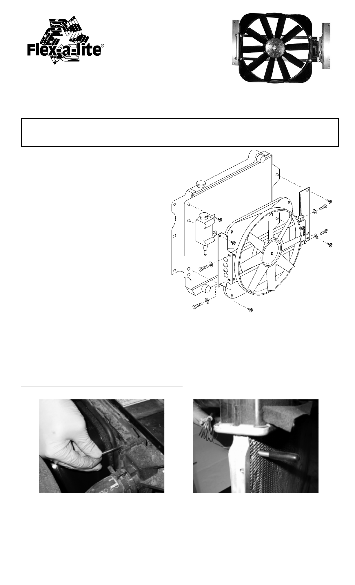
REMOVE OLD F AN & SHROUD
1. Remove rubber splash guard (if so equipped) at
bottom of fan shroud.
2. Remove 4 screws holding shroud to radiator, and
remaining screw holding power steering
reservoir. Tuck reservoir out of way temporarily.
Save all bolts. (Note: Shroud will not come out until
fan and fan clutch are unbolted.)
3. Remove four nuts holding fan and fan clutch
assembly to water pump hub. Remove fan clutch
assembly in one piece, along with old shroud. Do
NOT remove water pump pulley. Replace nuts
onto water pump hub and tighten.
Assemble new fan unit
1. Press plastic control knob onto the thermostat
shaft on Flex-a-lite fan shroud.
2. Screw left and right end brackets to fan as shown
with 3/8" bolts and flat washers supplied. Do not
tighten yet. See FIG . 1.
FIG. 1
INST ALL NEW F AN UNIT
1. Lower Flex-a-lite electric fan unit into place. Fan will squeeze between radiator hose and power steering
reservoir. Be careful not to damage radiator core with mounting brackets during install.
2. Hold fan in place and, using original shroud bolts, fasten through new brackets and into original mounting
points on radiator flange. The power steering reservoir locates in its original
position.
3. Making sure that rubber seal contacts radiator all around, tighten 3/8" bolts holding
fan to brackets.
.
Insert the temperature probe into the radiator fins
Install temp. probe near inlet hose... then replace the insulator cap.
Locate the inlet hose from the engine to the radiator . Remove the black insulator cap and insert the
temp. probe through the radiator fins near the inlet hose. Reinstall the black insulator cap.
rev . 06-16-06 99939 Page 1 of 2
Page 2
.
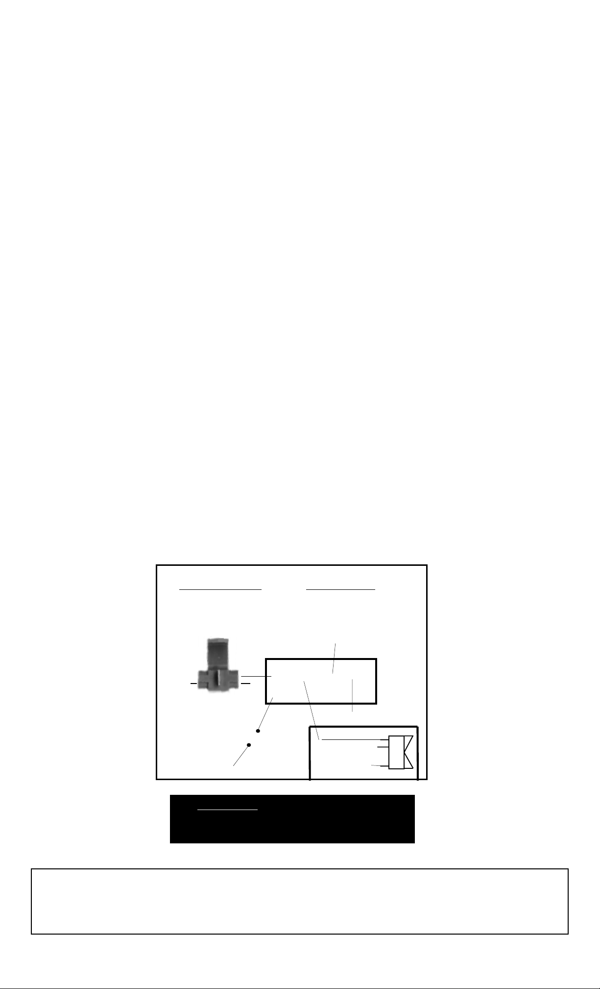
WIRING INSTRUCTIONS
Before proceeding, disconnect battery ground cable!
Otherwise, fan can come on unexpectedly .
2. Run a length of heavy (10 ga.) red wire (supplied) from battery to the “B” terminal using the thick red
wire and in line fuse holder provided in the kit.
3. Run a length of black wire from Ground (one of the screws holding Circuit Breaker is good) to terminal
"G" on the controller , located on the fan shroud, using the blue electrical connectors
supplied for terminal connections.
4. Run a length of thin (14 ga.) red wire to a 12V pos(+) source.
(If you want the fan to continue to run after vehicle is turned off and until radiator cools, run the wire
directly to the battery . Otherwise, wire it to an ignition-switched source. Connect the other end other
end to terminal "+" on the controller. Use the blue electrical connectors supplied for terminal connections.
Automatic A/C Relay Connection
If you have air conditioning, tap into the air conditioner’s positive lead using the brown plastic wire
connector , and run the green wire from there to terminal "C" on the controller. To make the
connection, snap the A/C lead into the p ass-thru channel of the connector, and fit the other end of the
green wire into the dead end channel in the connector . Use a pair of pliers to crimp the metal plate into
place. Snap the plastic cover closed.
Finish Up
Use nylon ties to keep wires orderly and prevent them from contacting hot or moving parts.
Especially , don't allow extra slack in the wire at the fan controller; wires could contact
alternator pulley or drive belt. Reconnect battery .
Adjusting the Fan Activation Temperature
St art engine and run until warmed up. Adjust fan activating temperature by turning plastic control knob.
Counterclockwise will activate fan at lower temps; clockwise for higher temps. Y ou may reset
the activating temperature to suit different driving conditions as you see fit, with no adverse effect
on the fan or control unit.
Control Box T erminals & Connections
Mandatory Connections
+ 12 volt positive source
G Ground
B 12 volt positive source
C Air conditioning relay
3-way
connector
A/C positive (+)
wire from clutch
Control Box
C
B
Optional Connection
M Manual switch
Ground
G
M
12 V olt Positive Source
+
Fuse Holder
12 V olt Positive Source
optional
12 Volt Source
Ground
(Illuminate switch)
12 3
*WARNING: If not using Flex-a-lite's
illuminated switch (PN #31148) you must
disconnect the switch ground.
The Flex-a-lite Limited Warranty
Flex-a-lite Consolidated, 7213-45th St. Ct. E. Fife, WA 98424, Telephone No. 253-922-2700, warrants to the original purchasing user, that all Flex-a-lite products to be free of
defects in material and workmanship for a period of 365 days (1 year) from date of purchase. Flex-a-lite products failing within 365 days (1 year) from date of purchase may
be returned to the factory through the point of purchase, transportation charges prepaid. If, on inspection, cause of failure is determined to be defective material or workmanship
and not by misuse, accidental or improper installation, Flex-a-lite will replace the fan free of charge, transportation prepaid. Flex-a-lite will not be liable for incidental,
progressive or consequential damages. Some states do not allow the exclusion or limitation of incidental or consequential damages, so the above limitation or exclusion may
not apply to you. This warranty gives you specific legal rights and you may have other rights, which vary from state to state.
The Flex-a-lite warranty is in compliance with the Magnuson-Moss Warranty Act of 1975.
rev . 06-16-06 99939 Page 2 of 2
 Loading...