

Page 1
Part #330
Dual Electric Fan with
Thermostatic Control
and A/C Relay
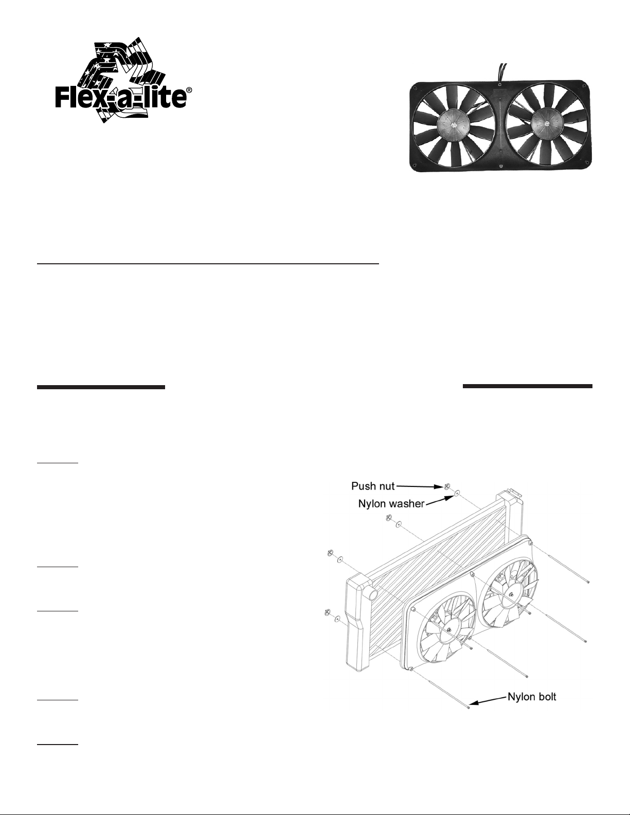
Setting Pull or Push Configuration:
At the factory, the model 330 is assembled to pull air. To push air, remove the
clips that hold the fan blades onto the motor shaft and turn the fan blade over.
Reinstall the clips to the motor shafts. Important: See wiring diagram (next
page), correct wiring must correspond with push or pull configuration.
Installation Instructions
Through Core Mounting Instructions
(see “Diagram A”)
Step 1: Position the electric fan against the
radiator, and mark the holes for mounting. (Some
applications may have A/C condensers and/or
transmission coolers on the front of the radiator.
Additional adjustments or modifications may be
necessary for installation).
Step 2: Rotate fan blades to make sure they are
free of obstructions.
Step 3: With a small Phillips screwdriver, pass
through the marked holes, carefully spreading the
fins to allow easy passage for the nylon bolts. Pass
the bolts through the shroud holes then twist the
bolts through the radiator.
Step 4: Slide the washer onto the nylon bolt and
push on the push nuts until snug.
Diagram A
Step 5: Trim off any excess length on the nylon
bolts with a pair of side cutters, leaving about ¼”
beyond the push nut.
Rev. 03-09-12 #98330 Page 1 of 4
Page 2
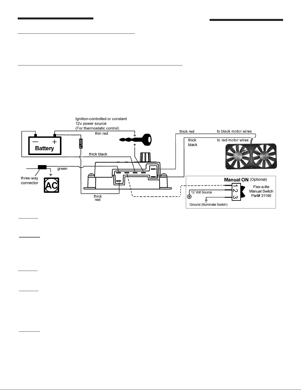
Wiring Instructions
Step 1: Locate mounting point for control
Locate a mounting point for control near inlet side of radiator. The control needs to be placed within
18” of radiator inlet hose. You may want to mount next to radiator on fender well. Mount the control
using the screws provided.
Step 2: Wire the fan motors (refer to wiring diagram, below)
Using the yellow butt connectors provided, attach a length of the thick (12 AWG) red wire to the black
motor wires at fan. Attach a length of the thick (12 AWG) black wire to the red motor wires at the fan.
Once the fan is in place, these will attach to the control module. If mounting the control somewhere in
the engine compartment, leave enough wire to reach the control module.
Note: Wiring for puller configuration is shown. For pusher configuration, fan blades must be flipped
over (see page 1) and wiring to motors reversed (large red to red motor wires, black to black motor
wires).
Step 3: Connect the wires crimped in Step 2 to the control module using supplied female connectors
(Red wire to the “M+” terminal and black wire to the “M-” terminal).
Step 4: Disconnect the negative battery lead for safety while finishing the wiring. Use the thick red
wire to run power directly from the battery positive (+) terminal to the “B” terminal on the control module. Connect the fuse holder in-line with this wire, as shown, but do not insert the fuse yet. Use the
blue female, ring, and butt connectors provided.
Step 5: Use the thick black wire to run from the negative (-) battery terminal to the “G” terminal on the
control module. Use the blue female connector and ring connector provided.
Step 6: Use the thin (18 AWG) red wire to connect the “+” terminal on the control module. Connect
the other end to a positive power source. NOTE: Attaching this wire to an ignition-controlled
source will shut off the fan when the engine is turned off. Attach this wire to an uninterrupted
(always hot) power source to allow the fan to continue running after the engine is shut off.
Use the blue female connector and fuse taps (included) if necessary.
Step 7: (Optional) For air conditioning control (if desired) connect the “C” terminal on the control
module to the positive wire that triggers the A/C compressor using the thin (18 AWG) green wire. Using a voltmeter, determine which wire coming from the compressor is the positive trigger wire. Use
the 3-way connector (included) to tap into this wire and send a signal to the fan control module. The
fan will cycle on and off with the A/C clutch when the A/C is turned on.
Rev. 03-09-12 #98330 Page 2 of 4
Page 3

Step 8: (Optional) For manual switch operation, use Flex-a-lite p/n 31148. Connect the switch as
shown on the wiring diagram (previous page). Connect the “M” terminal on the control module to the
“#1” terminal on the switch. Connect the “#2” terminal on the switch to a positive 12v power source.
Connect terminal “#3” on the switch to a good ground (for switch illumination). NOTE: To prevent
thermostatic activation (if only manual switch operation is desired), omit the lead to the “+” terminal of the control box. “B”, “G”, “M+” and “M-” must remain connected. If not using a Flexa-lite manual switch, do not connect a ground wire to the switch!
Step 9: Use the zip ties provided to secure the wires and prevent them from interfering with fan
blades, belts, and pulleys in the engine compartment. Reconnect the battery and insert the fuse provided.
Step 10: Locate the temperature sensor. Gently push probe through ns in radiator as close to the
upper radiator hose as possible. The rubber insulator cap should be used when possible to insulate
any of the probe coming through the front side of the radiator.
Install temp. probe near inlet hose...
then install the insulator cap.
Step 11: If you disconnected any hoses or drained coolant to install the fan, reconnect the hoses
and refill the radiator. Press the control knob (included in wiring kit) onto the control box shaft. Turn
the knob clockwise until it stops. Start the engine and allow it to idle. Using a hand held temperature
sensor (positioned near the inlet hose) or the vehicle’s temperature gauge, monitor the temperature.
When the coolant temp. is slightly above normal (or desired temp.), turn the knob counter-clockwise
just until the fan turns on. From now on, the fan should activate at this temperature setting. Adjust as
necessary to maintain desired temperature.
The Flex-a-lite Limited Warranty
Flex-a-lite Consolidated, 7213-45th St. Ct. E. Fife, WA 98424, Telephone No. 253-922-2700, warrants to the original purchasing user, that all Flex-a-lite products to be free of defects in material and
workmanship for a period of 365 days (1 year) from date of purchase. Flex-a-lite products failing within 365 days (1 year) from date of purchase may be returned to the factory through the point of
purchase, transportation charges prepaid. If, on inspection, cause of failure is determined to be defective material or workmanship and not by misuse, accidental or improper installation, Flex-a-lite
will replace the fan free of charge, transportation prepaid. Flex-a-lite will not be liable for incidental, progressive or consequential damages. Some states do not allow the exclusion or limitation
of incidental or consequential damages, so the above limitation or exclusion may not apply to you. This warranty gives you specific legal rights and you may have other rights, which vary from state
to state.The Flex-a-lite warranty is in compliance with the Magnuson-Moss Warranty Act of 1975.
Rev. 03-09-12 #98330 Page 3 of 4
Page 4

Troubleshooting the electric fan
Problem Possible Cause How to nd out Solution
Fan does not turn
on regardless of
temperature
Fan still does not turn onFuse to battery
Fan still does not turn onMotor wired
“+” terminal on control
box not connected to
proper source
positive post blown.
Wires to terminals
“B” and “G” aren’t
properly hooked up.
improperly
Trace wire connected
to the “+” terminal.
Use a voltmeter or
test light to check for
voltage.
Inspect the fuse in the
holder.
Check for power and
ground through lines
hooked to terminals
“B” & “G”.
Check to see that the
blue motor wire runs
to the “M+” terminal
and the black motor
wire runs to the “M-“
terminal on the control
box.
If there is no power to
the “+” terminal, nd
an ignition-switched or
constant 12v. power
source and wire it to
the “+” terminal on the
control box.
Replace fuse.
Hook up wires for
terminals “B” & “G” to
battery and ground
respectively.
Connect wires to
correct terminals.
If motor does not spin
after checking wiring,
call tech support at
1-800-851-1510.
Fan does not come on
until the temperature
is very hot
Fan was working
properly but suddenly
shut down
When engine is
started, fan comes on
even though engine is
cold
Temp. probe not
located in optimum
position
Temperature set to
high
Usage of a chassis
ground and/or
alternate source for
power other than
positive terminal on
battery
Constant (always
“hot”) 12v source
hooked to “C” terminal
Check location of
temp. probe.
Locate temperature
adjusting knob on top
cover of control box
Trace wire from
terminals “B” and “G”
to nd source.
Trace the wire
connected to the “C”
terminal and make
sure it is spliced into
the positive trigger
wire from the A/C
compressor clutch.
Temp. probe should
be located nearest the
upper radiator hose.
Turn knob counterclockwise to set the
control box to a lower
temperature.
Move to posts on the
battery.
Splice into the positive
trigger wire to the A/C
clutch and connect
to the “C” terminal on
control box.
A/C or defrost turned
on
Check if defrost
activates a/c or if the
a/c is on.
Rev. 03-09-12 #98330 Page 4 of 4
Shut off a/c or leave
on as this is normal
operation.
 Loading...