

Page 1

FLENDER COUPLINGS
N-EUPEX / N-EUPEX DS
Operating Instructions 3100en
Edition 10/2017
A, B, ADS, BDS
Page 2

21.09.2017 14:39
V6.00
Page 3

FLENDER COUPLINGS
N-EUPEX / N-EUPEX DS
3100en
A, B, ADS, BDS
Introduction
1
Operating Instructions
Safety instructions
Description
Application planning
Assembly
Commissioning
Operation
Servicing
2
3
4
5
6
7
8
Service and support
Disposal
Spare parts
Technical data
Quality documents
9
10
11
A
B
Edition 10/2017
Page 4

Legal information
Warning notice system
This manual contains notices you have to observe in order to ensure your personal safety, as well as to prevent
damage to property. The notices referring to your personal safety are highlighted in the manual by a safety alert
symbol, notices referring only to property damage have no safety alert symbol. These notices shown below are
graded according to the degree of danger.
DANGER
indicates that death or severe personal injury will result if proper precautions are not taken.
WARNING
indicates that death or severe personal injury may result if proper precautions are not taken.
CAUTION
indicates that minor personal injury can result if proper precautions are not taken.
NOTICE
indicates that property damage can result if proper precautions are not taken.
If more than one degree of danger is present, the warning notice representing the highest degree of danger will be
used. A notice warning of injury to persons with a safety alert symbol may also include a warning relating to property
damage.
Qualified Personnel
The product/system described in this documentation may be operated only by personnel qualified for the specific
task in accordance with the relevant documentation, in particular its warning notices and safety instructions. Qualified
personnel are those who, based on their training and experience, are capable of identifying risks and avoiding
potential hazards when working with these products/systems.
Proper use of Flender products
Note the following:
WARNING
Flender products may only be used for the applications described in the catalog and in the relevant technical
documentation. If products and components from other manufacturers are used, these must be recommended or
approved by Flender. Proper transport, storage, installation, assembly, commissioning, operation and maintenance
are required to ensure that the products operate safely and without any problems. The permissible ambient
conditions must be complied with. The information in the relevant documentation must be observed.
Trademarks
All names identified by ® are registered trademarks of Flender GmbH. The remaining trademarks in this publication
may be trademarks whose use by third parties for their own purposes could violate the rights of the owner.
Disclaimer of Liability
We have reviewed the contents of this publication to ensure consistency with the hardware and software described.
Since variance cannot be precluded entirely, we cannot guarantee full consistency. However, the information in
this publication is reviewed regularly and any necessary corrections are included in subsequent editions.
Flender GmbH
Alfred-Flender-Straße 77
46395 BOCHOLT
GERMANY
Document order number: 3100en
Ⓟ 09/2017 Subject to change
Copyright © Flender GmbH 2016, -,
2017.
All rights reserved
Page 5

Table of contents
1 Introduction...................................................................................................................................................9
1.1 About these instructions...........................................................................................................9
1.2 Text attributes..........................................................................................................................9
1.3 Copyright..................................................................................................................................9
2 Safety instructions......................................................................................................................................11
2.1 General information................................................................................................................11
2.2 Intended use..........................................................................................................................13
2.3 Safety instructions for a coupling for use in potentially explosive atmospheres....................13
2.3.1 Marking..................................................................................................................................13
2.3.2 Conditions of use...................................................................................................................15
2.4 General warning notices........................................................................................................16
3 Description..................................................................................................................................................19
4 Application planning...................................................................................................................................21
4.1 Transport of the coupling.......................................................................................................21
4.2 Storage of the coupling..........................................................................................................21
5 Assembly....................................................................................................................................................23
5.1 Preparatory work....................................................................................................................23
5.1.1 Milling the parallel keyway.....................................................................................................24
5.1.2 Milling the parallel keyway.....................................................................................................25
5.1.3 Machining an axial locking mechanism..................................................................................26
5.1.4 Balancing the coupling...........................................................................................................28
5.2 Assembling the coupling........................................................................................................30
5.3 Aligning the coupling..............................................................................................................31
5.3.1 Purpose of alignment.............................................................................................................31
5.3.2 Possible misalignment...........................................................................................................32
5.3.2.1 Axial misalignment.................................................................................................................32
5.3.2.2 Angular misalignment.............................................................................................................32
5.3.2.3 Radial misalignment...............................................................................................................33
6 Commissioning...........................................................................................................................................35
7 Operation....................................................................................................................................................37
7.1 Normal operation of the coupling...........................................................................................37
7.2 Faults - causes and rectification.............................................................................................37
7.2.1 Procedure in the event of malfunctions..................................................................................37
7.2.2 Identifying the fault cause......................................................................................................37
7.2.2.1 Possible faults........................................................................................................................38
7.2.2.2 Possible causes.....................................................................................................................39
N-EUPEX / N-EUPEX DS 3100en
Operating Instructions 10/2017 5
Page 6

Table of contents
7.2.3 Correcting faults.....................................................................................................................40
7.2.3.1 Replacing wearing parts.........................................................................................................40
7.2.3.2 Correcting the changed alignment.........................................................................................41
8 Servicing.....................................................................................................................................................43
8.1 Maintenance intervals............................................................................................................43
8.2 Maximum permissible torsional backlash...............................................................................44
8.3 Replacing wearing parts.........................................................................................................45
8.4 Removing the coupling...........................................................................................................46
9 Service and support....................................................................................................................................49
9.1 Contact...................................................................................................................................49
10 Disposal......................................................................................................................................................51
11 Spare parts.................................................................................................................................................53
11.1 Ordering spare parts..............................................................................................................53
11.2 Spare parts drawing and spare parts list................................................................................54
11.2.1 Types A and ADS...................................................................................................................54
11.2.2 Types B and BDS...................................................................................................................55
A Technical data............................................................................................................................................57
A.1 Speeds, geometry data and weights......................................................................................57
A.1.1 Type A....................................................................................................................................57
A.1.2 Type B....................................................................................................................................59
A.1.3 Type ADS...............................................................................................................................60
A.1.4 Type BDS...............................................................................................................................61
A.2 Shaft misalignment values during operation..........................................................................62
A.3 Tightening torques and widths A/F.........................................................................................63
A.4 Tightening procedure.............................................................................................................64
A.5 Flexible elements (12)............................................................................................................64
A.5.1 Use and storage of flexible elements (12)..............................................................................64
A.5.2 N-EUPEX flexible elements (12)............................................................................................65
A.5.3 N-EUPEX DS flexible elements (12)......................................................................................66
B Quality documents......................................................................................................................................67
B.1 Declaration of Conformity.......................................................................................................67
Tables
Table 2-1 General warnings........................................................................................................................11
Table 2-2 Temperature classes (TX) for explosive atmospheres as a result of gases, vapours or mists......16
Table 2-3 Maximum surface temperature (TX) for an explosive atmosphere as a result of dust/air
mixtures.......................................................................................................................................16
Table 4-1 Types of preservative agents for long-term storage....................................................................22
Table 5-1 Recommended assigned fits for bores with parallel key connection...........................................24
N-EUPEX / N-EUPEX DS 3100en
6 Operating Instructions 10/2017
Page 7

Table of contents
Table 5-2 Position of the parallel keyway....................................................................................................25
Table 5-3 Diameter and axial position of the tapped hole, tightening torque..............................................27
Table 5-4 Position of the tapped hole with respect to the parallel keyway..................................................28
Table 7-1 Table of faults..............................................................................................................................38
Table 8-1 Maintenance intervals.................................................................................................................43
Table 8-2 Maximum permissible torsional backlash for the types A and B (sizes 58 to 250)......................44
Table 8-3 Maximum permissible torsional backlash for the types A and B (sizes 280 to 710)....................44
Table 8-4 Maximum permissible torsional backlash for the types ADS and BDS (sizes 66 to 218)............44
Table 8-5 Maximum permissible torsional backlash for the types ADS and BDS (sizes 245 to 556)..........45
Table 11-1 Spare parts list for types A and ADS...........................................................................................54
Table 11-2 Spare parts list for types B and BDS...........................................................................................55
Table A-1 Speeds, geometry data and weights of type A............................................................................57
Table A-2 Speeds, geometry data and weights of type B............................................................................59
Table A-3 Speeds, geometry data and weights of type ADS.......................................................................60
Table A-4 Speeds, geometry data and weights of type BDS.......................................................................61
Table A-5 Maximum permissible shaft misalignment values during operation............................................62
Table A-6 Tightening torques for part 13 of types A and ADS.....................................................................63
Table A-7 Tightening procedure..................................................................................................................64
Table A-8 N‑EUPEX flexible elements.........................................................................................................65
Table A-9 N‑EUPEX DS flexible elements...................................................................................................66
Figures
Figure 3-1 Type A and ADS..........................................................................................................................19
Figure 3-2 Type B and BDS..........................................................................................................................20
Figure 4-1 Transport symbols.......................................................................................................................21
Figure 5-1 Tolerances for finished bore........................................................................................................25
Figure 5-2 Diameter and axial position of the tapped hole in the hub..........................................................26
Figure 5-3 Position of the balancing bore for single-plane balancing...........................................................29
Figure 5-4 Position of the balancing bore for two-plane balancing...............................................................29
Figure 5-5 Possible misalignment.................................................................................................................32
Figure 8-1 Markings for calculating the torsional backlash...........................................................................44
Figure 8-2 Tapped jacking hole for loosening coupling part 3 (3).................................................................45
Figure 11-1 Spare parts drawing for types A and ADS...................................................................................54
Figure 11-2 Spare parts drawing for types B and BDS...................................................................................55
Figure A-1 Type A.........................................................................................................................................57
Figure A-2 Type B.........................................................................................................................................59
Figure A-3 Type ADS....................................................................................................................................60
Figure A-4 Type BDS....................................................................................................................................61
N-EUPEX / N-EUPEX DS 3100en
Operating Instructions 10/2017 7
Page 8

Table of contents
N-EUPEX / N-EUPEX DS 3100en
8 Operating Instructions 10/2017
Page 9

Introduction
1.1 About these instructions
These instructions describe the coupling and provide information about its handling - from
assembly to maintenance. Please keep these instructions for later use.
Please read these instructions prior to handling the coupling and follow the information in them.
1.2 Text attributes
The warning notice system is explained on the back of the inner cover. Always follow the safety
information and notices in these instructions.
In addition to the warning notices, which have to be observed without fail, you will find the
following text attributes in these instructions:
1. Procedural instructions are shown as a numbered list. Always perform the steps in the order
given.
● Lists are formatted as bulleted lists.
– The dash is used for lists at the second level.
1
(1) Numbers in brackets are part numbers.
Note
A note is an important item of information about the product, the handling of the product or the
relevant section of the instructions. The note provides you with help or further suggestions/
ideas.
1.3 Copyright
The copyright for these instructions is held by Flender.
These instructions must not be used wholly or in parts without our authorisation or be given to
third parties.
If you have any technical queries, please contact our factory or one of our service outlets (refer
to Service and support (Page 49)).
N-EUPEX / N-EUPEX DS 3100en
Operating Instructions 10/2017 9
Page 10

Introduction
1.3 Copyright
N-EUPEX / N-EUPEX DS 3100en
10 Operating Instructions 10/2017
Page 11

Safety instructions
2.1 General information
Instructions
These instructions are part of the delivery. Always keep these instructions close to the coupling.
Please make sure that every person who is commissioned to work on the coupling has read
and understood these instructions prior to handling the coupling and observes all of the points.
Only the knowledge of these instructions can avoid faults on the coupling and ensure fault-free
and safe operation. Non-adherence to the instructions can cause product or property damage
or personal injury. Flender does not accept any liability for damage or operating failures that
are due to non-adherence to these instructions.
State of the art
The coupling described here has been designed in consideration of the latest findings for
demanding technical requirements. This coupling is state-of-the-art at the time of printing these
instructions.
In the interest of further development, Flender reserves the right to make such changes to the
individual components and accessories that increase performance and safety whilst
maintaining the essential features.
2
Symbols
Table 2-1 General warnings
ISO ANSI Warning
Warning - hazardous electrical voltage
Warning - explosive substances
--- Warning - entanglement hazard
--- Warning - hot surfaces
--- Warning - substances that are harmful to health or are irritants
N-EUPEX / N-EUPEX DS 3100en
Operating Instructions 10/2017 11
Page 12

Safety instructions
2.1 General information
ISO ANSI Warning
--- Warning - corrosive substances
--- Warning - suspended load
--- Warning - hand injuries
ATEX certification
Explanation regarding Machinery Directive 2006/42/EC
The couplings described here are “components” in accordance with the Machinery Directive
and do not require a declaration of incorporation.
ATEX Directive
Protective clothing
Using the coupling
The term "ATEX Directive" used in these instructions stands for the harmonisation legislation
of the European Union in compliance with the declaration of conformance for equipment and
protective systems for correct use in hazardous zones.
In addition to the generally prescribed personal protective equipment (safety shoes, overalls,
helmet, etc.), also wear suitable safety gloves and safety goggles when handling the coupling.
The relevant work safety and environmental protection regulations must be complied with at
all times during transport, assembly, installation, dismantling, operation and maintenance of
the coupling.
Only qualified personnel may operate, assemble, maintain and repair the coupling. Information
about qualified personnel can be found in the legal notes at the beginning of these instructions.
If lifting gear or load suspension devices are used for transporting, these have to be suitable
for the weight of the coupling.
If the coupling has visible damage, it may not be assembled or put into operation.
The coupling may only be operated in a suitable housing or with touch protection according to
applicable standards. This also applies to test runs and rotational direction checks.
Work on the coupling
Only carry out work on the coupling when it is not in operation and is not under load.
N-EUPEX / N-EUPEX DS 3100en
12 Operating Instructions 10/2017
Page 13

Secure the drive unit against being switched on accidentally. Attach a notice to the switch
stating clearly that work is being carried out on the coupling. Ensure that the entire unit is not
under load.
2.2 Intended use
Only use the coupling according to the conditions specified in the service and delivery contract
and the technical data in the annex. Deviating operating conditions are considered improper
use. The user or owner of the machine or plant is solely liable for any resulting damage.
When using the coupling please specifically observe the following:
● Do not make any modifications to the coupling that go beyond the permissible machining
described in these instructions. This also applies to touch protection facilities.
● Only use original spare parts from Flender. Flender only accepts liability for original spare
parts from Flender.
Other spare parts are not tested and approved by Flender. Non-approved spare parts may
possibly change the design characteristics of the coupling and thus impact active and/or
passive safety.
Flender will accept no liability or warranty whatsoever for damage occurring as a result of
the use of non-approved spare parts. The same applies to any accessories that were not
supplied by Flender.
Safety instructions
2.2 Intended use
If you have any queries, please contact our customer service (see Service and support
(Page 49)).
2.3 Safety instructions for a coupling for use in potentially explosive atmospheres
2.3.1 Marking
You can find a description of the coupling parts in chapter Description (Page 19).
A coupling designed in accordance with the ATEX Directive has a marking on the coupling
parts.
Coupling part 1 without electrically insulating flexible elements
One of the following markings is visible on the outer diameter of coupling part 1:
Version 1:
Flender GmbH II 2GD c IIC TX
46393 Bocholt - Germany I M2 c X
FLENDER couplings N‑EUPEX <Year of man‐
ufacture>
N-EUPEX / N-EUPEX DS 3100en
Operating Instructions 10/2017 13
Page 14

Safety instructions
2.3 Safety instructions for a coupling for use in potentially explosive atmospheres
Version 2:
Flender GmbH II 2G c IIC T4/T5/T6
-30 °C ≤ Ta ≤ +80 °C/+70 °C/+55 °C
46393 Bocholt - Germany II 2D c T 110 °C -30 °C ≤ Ta ≤ +80 °C
FLENDER couplings N‑EUPEX <Year of man‐
ufacture>
Coupling part 1 with flexible elements for low-temperature use
One of the following markings is visible on the outer diameter of coupling part 1:
Version 1:
Flender GmbH II 2GD c IIC TX
46393 Bocholt - Germany I M2 c X
FLENDER couplings N‑EUPEX <Year of man‐
ufacture>
Version 2:
Flender GmbH II 2G c IIC T6 -50 °C ≤ Ta ≤ +50 °C
46393 Bocholt - Germany II 2D c T 80 °C -50 °C ≤ Ta ≤ +50 °C
FLENDER couplings N‑EUPEX <Year of man‐
ufacture>
I M2 c -30 °C ≤ Ta ≤ +80 °C
I M2 c -50 °C ≤ Ta ≤ +50 °C
Coupling part 1 with electrically insulating flexible elements
One of the following markings is visible on the outer diameter of coupling part 1:
Version 1:
Flender GmbH II 2GD c IIB TX
46393 Bocholt - Germany I M2 c X
FLENDER couplings N‑EUPEX <Year of man‐
ufacture>
Version 2:
Flender GmbH II 2G c IIB T4/T5/T6
46393 Bocholt - Germany II 2D c T 110 °C -30 °C ≤ Ta ≤ +80 °C
FLENDER couplings N‑EUPEX <Year of man‐
ufacture>
14 Operating Instructions 10/2017
-30 °C ≤ Ta ≤ +80 °C/+70 °C/+55 °C
I M2 c -30 °C ≤ Ta ≤ +80 °C
N-EUPEX / N-EUPEX DS 3100en
Page 15

Coupling part 2 or 4
Safety instructions
2.3 Safety instructions for a coupling for use in potentially explosive atmospheres
Coupling part 2 or coupling part 4 is stamped with
Undrilled or predrilled coupling
A coupling part with Ex marking, the letter "U" and the Flender order number has been delivered
undrilled or predrilled.
Note
Undrilled or predrilled coupling with Ex marking
Flender only supplies an undrilled or predrilled coupling with Ex marking on the condition that
the customer assumes the responsibility and liability for correct finishing work in a declaration
of exemption.
2.3.2 Conditions of use
Note
Note also the material-dependent permissible ambient temperature of the flexible elements
(12) in accordance with sections N-EUPEX flexible elements (12) (Page 65) and N-EUPEX
DS flexible elements (12) (Page 66).
.
A coupling designed in accordance with the ATEX Directive is suitable for the following
conditions of use:
● Equipment group I
– Category M2
● Equipment group II
– Category 2 and 3
– Group of substances G, zone 1 and 2
– Group of substances D, zone 21 and 22
– Explosion group IIA, IIB and IIC
– Explosion group IIA and IIB when electrically insulating flexible elements are used
Conditions of use for products with TX marking
The maximum ambient temperature stated in the following tables applies to the temperature
in the direct vicinity of the coupling and the temperature of adjacent components.
N-EUPEX / N-EUPEX DS 3100en
Operating Instructions 10/2017 15
Page 16

Safety instructions
2.4 General warning notices
1. Gases, vapours or mists
Check the ambient temperature for use of the coupling in the relevant temperature class.
Table 2-2 Temperature classes (TX) for explosive atmospheres as a result of gases, vapours or mists
2. Dust/air mixtures
Check the ambient temperature.
Table 2-3 Maximum surface temperature (TX) for an explosive atmosphere as a result of dust/air
Max. ambient temperature Temperature class
80 °C T4
70 °C T5
55 °C T6
mixtures
Max. ambient temperature Max. surface temperature
80 °C 110 °C
Notes concerning operation of the coupling in potentially explosive atmospheres
● Only use the coupling underground in mines in potentially explosive atmospheres together
with drive motors that can be switched off in the event of the formation of an explosive
atmosphere.
● Earth machines that are connected via the coupling with a leakage resistance of less than
106 Ω.
● If you want to use a coated coupling in potentially explosive atmospheres, please note the
requirements concerning the conductivity of the paint and the limitation on the paint layer
thickness applied in accordance with EN 13463-1. No build-up of electrostatic charges is
to be expected with a paint layer thickness of less than 200 μm.
2.4 General warning notices
DANGER
Danger due to bursting of the coupling
The coupling may burst if it is not used properly. There is a risk of fatal injury from flying
fragments. Bursting of the coupling can lead to an explosion in potentially explosive
atmospheres.
● Use the coupling for the purpose for which it is intended.
N-EUPEX / N-EUPEX DS 3100en
16 Operating Instructions 10/2017
Page 17

Safety instructions
2.4 General warning notices
DANGER
Risk of explosion when using coupling parts without Ex marking
Coupling parts without Ex marking have not been approved for use in potentially explosive
atmospheres. These coupling parts can lead to an explosion during operation.
● Only use couplings with Ex marking in potentially explosive atmospheres.
DANGER
Danger
Risk of injury due to the use of unsuitable and/or damaged components. The use of unsuitable
and/or damaged components can lead to an explosion in potentially explosive atmospheres.
● Observe the information regarding conditions of use.
DANGER
Danger of explosion
Improper operation of the coupling can lead to an explosion in potentially explosive
atmospheres.
● Please observe the notes concerning operation of the coupling in potentially explosive
atmospheres.
DANGER
Danger from hot coupling parts
Risk of injury due to hot surfaces. Hot coupling parts can lead to an explosion in potentially
explosive atmospheres.
● Wear suitable protective equipment (gloves, safety goggles).
● Ensure that the area is not at risk of explosion.
WARNING
Risk of chemical burns due to chemical substances
There is a risk of chemical burns when handling aggressive cleaning agents.
● Please observe the manufacturer's information on how to handle cleaning agents and
solvents.
● Wear suitable protective equipment (gloves, safety goggles).
CAUTION
Physical injury
Risk of injury due to falling coupling parts.
● Secure the coupling parts to prevent them from falling.
N-EUPEX / N-EUPEX DS 3100en
Operating Instructions 10/2017 17
Page 18

Safety instructions
2.4 General warning notices
N-EUPEX / N-EUPEX DS 3100en
18 Operating Instructions 10/2017
Page 19

Description
Application
Design
3
The N‑EUPEX or N‑EUPEX DS couplings described here are torsionally flexible, damping pin
couplings and are available in various types and sizes. The couplings can be used in
accordance with the ATEX Directive in potentially explosive atmospheres if they have a CE
marking.
Types A and B are fail-safe. Types ADS and BDS have no fail-safe device.
These instructions describe the assembly and operation of an N‑EUPEX or N‑EUPEX DS
coupling arranged horizontally with a shaft-hub connection made by a cylindrical or conical
bore with parallel key. Please consult Flender if you want to use a different type of installation.
N‑EUPEX couplings are designed for use in all kinds of machines.
N‑EUPEX DS couplings are used for applications which require the input and output to be
disconnected from one another in the event of destruction of the flexible elements.
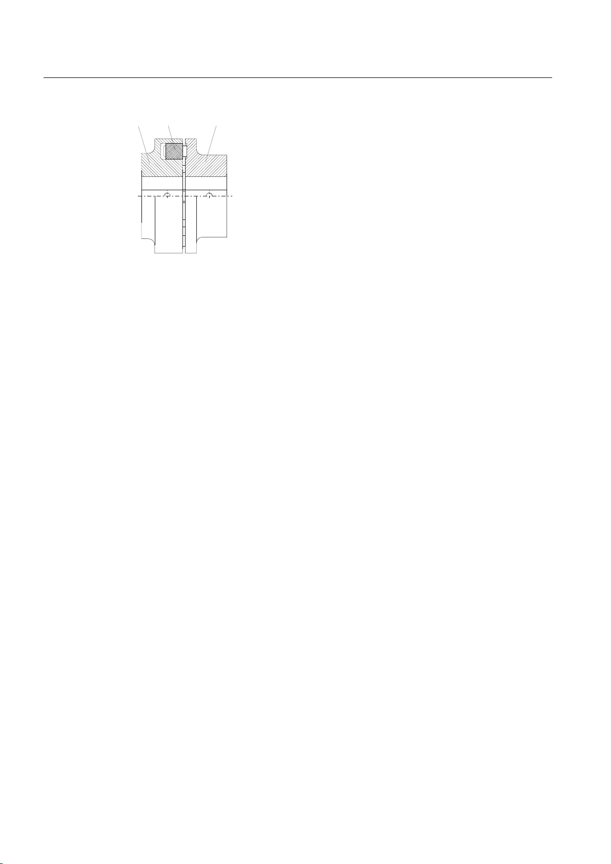
The diagrams show the various types with their constituent parts and their part numbers.
N-EUPEX / N-EUPEX DS 3100en
Operating Instructions 10/2017 19
1 Coupling part 1
2 Coupling part 2
3 Coupling part 3
12 Flexible element
13 Cylinder-head screw
16 Cylindrical pin
only with type A sizes 560 to 710
Figure 3-1 Type A and ADS
Page 20
Description
1 Coupling part 1
4 Coupling part 4
12 Flexible element
Figure 3-2 Type B and BDS
20 Operating Instructions 10/2017
N-EUPEX / N-EUPEX DS 3100en
Page 21
Application planning
7KLVZD\XS)UDJLOH.HHS
GU\
.HHS
GU\
&HQWUHRIJUDYLW\'RQRW
XVHKDQGKRRN
$WWDFKKHUH
Check the delivery for damage and for completeness. Report any damage and/or missing parts
to Flender immediately.
The coupling is delivered in individual parts and preassembled groups. Preassembled groups
may not be dismantled.
4.1 Transport of the coupling
WARNING
Severe personal injury due to improper transport
Severe personal injury due to falling components or due to crushing. Damage to coupling
parts possible due to use of unsuitable transport means.
● Only use lifting gear and load suspension devices with sufficient load bearing capacity for
transport.
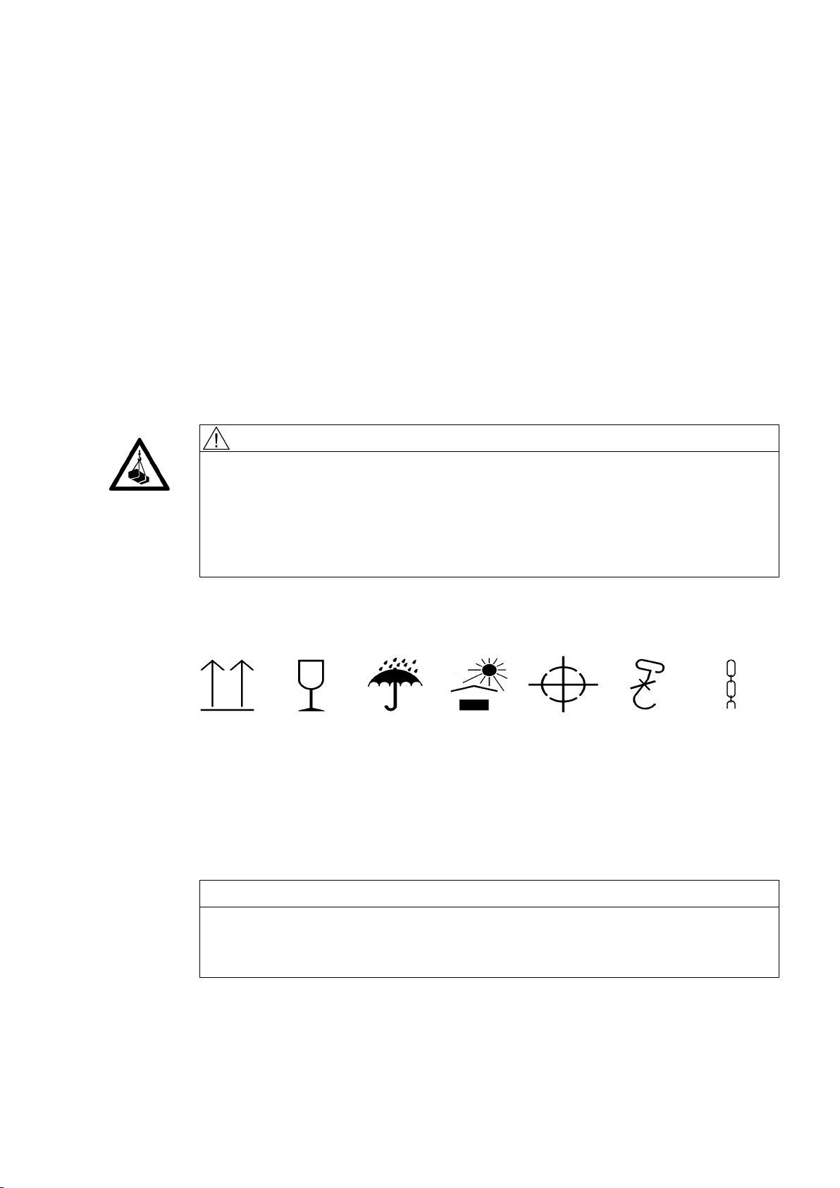
● Please observe the symbols applied on the packaging.
4
If not specifically contractually agreed otherwise, the packaging complies with the HPE
Packaging Directive.
Figure 4-1 Transport symbols
4.2 Storage of the coupling
NOTICE
Property damage due to improper storage
Negative changes to the physical properties of the coupling and/or coupling damage.
● Please observe the information about storing the coupling.
N-EUPEX / N-EUPEX DS 3100en
Operating Instructions 10/2017 21
Page 22

Application planning
4.2 Storage of the coupling
The coupling, unless not specifically ordered otherwise, is supplied with preservation and can
be stored for up to 3 months.
Note
Information about storing the coupling
● Ensure that the storage room is dry (relative humidity < 65 %) and free of dust.
● Ensure that there is no condensation.
● Do not store the coupling together with corrosive chemicals, acids, caustic solutions, etc.
● If the coupling contains elastomer components, ensure that there are no devices in the
storage room that produce ozone, such as fluorescent lights, mercury vapour lamps or highvoltage electrical equipment.
● Store the coupling on suitable supports or in suitable containers.
Long-term storage
NOTICE
Property damage due to improper long-term storage
Negative changes to the physical properties of the coupling and/or coupling damage.
● Note the handling instructions for long-term storage.
1. You can find the required type of preservative agent in the following table (types of
preservative agents for long-term storage).
2. Remove the elastomer components. These must not come into contact with cleaning agents
and long-term preservative agents.
3. Clean the coupling parts.
4. Apply the stipulated preservative agent.
5. Store the coupling parts and the elastomer components separately.
Table 4-1 Types of preservative agents for long-term storage
Preservative agents Features Indoor storage Outdoor storage
Oil spray Anti-corrosion agent Up to 12 months Up to 4 months
Tectyl 846 or similar Long-term preservative agent on
wax basis
Emulsion cleaner + VCI foil Active system, reusable Up to 5 years Up to 5 years
Up to 36 months Up to 12 months
N-EUPEX / N-EUPEX DS 3100en
22 Operating Instructions 10/2017
Page 23

Assembly
5
Assembly of the coupling comprises the following steps:
● Preparatory work (Page 23)
● Assembling the coupling (Page 30)
● Aligning the coupling (Page 31)
DANGER
Danger due to bursting of the coupling
If you do not observe the information stipulated here regarding assembly, this can lead to
bursting of the coupling during operation. There is a risk of fatal injury from flying fragments.
Bursting of the coupling can lead to an explosion in potentially explosive atmospheres.
● Please observe all the stipulations concerning assembly.
Note
Information about the assembly of the coupling
● Only use undamaged components for the assembly of the coupling.
● Follow the assembly sequence.
● Please ensure that there is sufficient space at the assembly location and that the location
is tidy and clean in order to be able to assemble and maintain the coupling without any risk.
● If a dimension drawing has been created for the coupling, please observe the information
it contains as a matter of priority.
5.1 Preparatory work
Note
Please consult Flender if you want to machine a conical finished bore.
Carry out the following steps if the coupling does not have a finished bore:
● Milling the parallel keyway (Page 24)
● Milling the parallel keyway (Page 25)
● Machining an axial locking mechanism (Page 26)
● Balancing the coupling (Page 28)
N-EUPEX / N-EUPEX DS 3100en
Operating Instructions 10/2017 23
Page 24

Assembly
5.1 Preparatory work
Note
The customer is responsible for execution of the finishing work on the coupling. Flender shall
have no liability whatsoever for claims under warranty arising from finishing work that has not
been carried out adequately.
5.1.1 Milling the parallel keyway
The diameter of the finished bore depends on the shaft used.
Recommended assigned fits
In the following table you can find the recommended assigned fits for bores with a parallel key
connection. The assigned fit m6 / H7 is especially suitable for a host of applications.
Table 5-1 Recommended assigned fits for bores with parallel key connection
Procedure
Description Push fit Press fit Interference fit
Not suitable for reversing operation Suitable for reversing operation
Shaft tolerance j6 h6 h6 k6 m6 n6 h6
Bore tolerance H7 J7 K7 H7 H7 H7 M7
1. Remove the flexible elements (12).
2. Remove the preservation and clean the coupling parts 1 (1) and 2 (2) or 4 (4) to be machined.
3. Clamp the coupling to the areas marked with
in the diagram below.
4. Machine the finished bore in accordance with the diagram below.
Note
Diameter of the finished bore
The diameter of the finished bore may not exceed the specified maximum diameter.
● Please observe the maximum diameters specified in section Speeds, geometry data
and weights (Page 57).
N-EUPEX / N-EUPEX DS 3100en
24 Operating Instructions 10/2017
Page 25

,7$
$
'7,%7,
,7&
,7&
'&%
7,7,7,7,
ෘ'
ෘ'
ෘ'
ෘ'
① Coupling part 1
② Coupling part 4
③ Coupling part 2
④ Coupling part 2/3
Figure 5-1 Tolerances for finished bore
Assembly
5.1 Preparatory work
5.1.2 Milling the parallel keyway
Position of the parallel keyway
The table below states the required position for the parallel keyway in the coupling parts
depending on the coupling type.
Table 5-2 Position of the parallel keyway
Coupling part Coupling Position of the parallel keyway
1 N‑EUPEX Centred between the flexible element webs
1 N‑EUPEX DS Centred between the flexible element pockets
2 N‑EUPEX Centred between the tapped holes
2 N‑EUPEX DS Centred between the tapped holes and offset relative to the
4 N‑EUPEX
N‑EUPEX DS
recesses for replacement of flexible elements
Beneath a cam
N-EUPEX / N-EUPEX DS 3100en
Operating Instructions 10/2017 25
Page 26

GGGG
HHHH
Assembly
5.1 Preparatory work
Applicable standards
● If the coupling is intended for use under normal operating conditions, mill the parallel
keyway according to DIN 6885/1 ISO JS9.
● If the coupling is intended for reversing operation, mill the parallel keyway according to
DIN 6885/1 ISO P9.
● If you want to mill a parallel keyway that does not correspond to DIN 6885/1, please consult
Flender.
5.1.3 Machining an axial locking mechanism
The coupling part is secured by a set screw or an end plate to prevent axial movements.
Please consult Flender if you want to use an end plate.
Note the following when using a set screw:
● Diameter and axial position of the tapped hole in the hub
● Position of the tapped hole with respect to the parallel keyway
● Selection of the set screw
Diameter and axial position of the tapped hole in the hub
The following diagram shows the axial position of the tapped hole.
① Coupling part 1; axial position of the tapped hole up to size 125 / 135
② Coupling part 1; axial position of the tapped hole as of size 140 / 152
③ Coupling part 2
④ Coupling part 4
Figure 5-2 Diameter and axial position of the tapped hole in the hub
26 Operating Instructions 10/2017
N-EUPEX / N-EUPEX DS 3100en
Page 27

Assembly
5.1 Preparatory work
The following table contains the values for the diameter and axial position of the tapped hole
depending on the size of the coupling.
Table 5-3 Diameter and axial position of the tapped hole, tightening torque
Size
d1
58 / 66 M5 10 - - 8 3
68 / 76 M6 10 - - 8 4
80 / 88 M6 11 - - 12 4
95 / 103 M6 15 - - 15 4
110 / 118 M6 18 - 9 18 4
125 / 135 M8 20 - 12 20 8
140 / 152 M8 - 13 15 22 8
160 / 172 M10 - 13 20 25 15
180 / 194 M12 - 16 30 32 25
200 / 218 M12 - 20 30 40 25
225 / 245 M12 - 22 35 40 25
250 / 272 M16 - 24 40 45 70
280 / 305 M16 - 28 45 45 70
315 / 340 M16 - 35 50 - 70
350 / 380 M20 - 40 60 - 130
400 / 430 M20 - 50 70 - 130
440 / 472 M24 - 60 80 - 230
480 / 514 M24 - 70 90 - 230
520 / 556 M24 - 80 100 - 230
560 M24 - 75 100 - 230
610 M24 - 85 110 - 230
660 M24 - 100 130 - 230
710 M24 - 115 140 - 230
e1
mm
e2
mm
e3
mm
e4
mm
Tightening torque
T
Nm
A
Apply the recommended tightening torques in accordance with the stipulations in section
Tightening procedure (Page 64).
N-EUPEX / N-EUPEX DS 3100en
Operating Instructions 10/2017 27
Page 28

Assembly
5.1 Preparatory work
Position of the tapped hole with respect to the parallel keyway
The tapped hole for the set screw is generally positioned on the parallel keyway. This does
not apply to the coupling parts listed in the following table.
Table 5-4 Position of the tapped hole with respect to the parallel keyway
Coupling part Size Finished bore
Selection of the set screw
CAUTION
Physical injury
Danger of injury from protruding set screw.
● Please observe the information about selecting the set screw.
As set screws use threaded studs in accordance with ISO 4029 with a toothed cup point. The
size of the set screw is determined by the bore made. The set screw should fill out the tapped
hole as much as possible and must not protrude beyond the hub.
Position of the tapped hole
[mm]
1 58 / 66 ≥ 15 Offset 180° relative to parallel keyway
68 / 76 ≥ 20 Offset 144° relative to parallel keyway
80 / 88 ≥ 25 Offset 180° relative to parallel keyway
95 / 103 ≥ 38 Offset 180° relative to parallel keyway
2 110 / 118 ≥ 30 Offset 180° relative to parallel keyway
4 58 / 66 ≥ 18 Offset 180° relative to parallel keyway
68 / 76 ≥ 20 Offset 180° relative to parallel keyway
5.1.4 Balancing the coupling
Notes on balancing the coupling
NOTICE
Damage to coupling part 1 (1)
If you completely drill through the base of a flexible element pocket on coupling part 1 (1),
then coupling part 1 (1) is no longer allowed to be used for operation.
● Please observe the stipulations about machining the balancing hole.
N-EUPEX / N-EUPEX DS 3100en
28 Operating Instructions 10/2017
Page 29

Assembly
5.1 Preparatory work
Please note the following when balancing the coupling:
● Select the balancing quality according to the application (but at least G16 in accordance
with DIN ISO 21940).
● Observe the balancing specification according to DIN ISO 21940-32.
● Machine the balancing bore on a large radius with adequate clearance to the flexible
element webs / pockets and to the cams and the outer circumference.
① Balancing bore
② Part 1 for N‑EUPEX or N‑EUPEX DS coupling
③ Part 2 for N‑EUPEX or N‑EUPEX DS coupling
④ Part 4 for N‑EUPEX or N‑EUPEX DS coupling
Figure 5-3 Position of the balancing bore for single-plane balancing
① Balancing bore
② Part 1 for N‑EUPEX or N‑EUPEX DS coupling
③ Part 2 for N‑EUPEX or N‑EUPEX DS coupling
④ Part 4 for N‑EUPEX or N‑EUPEX DS coupling
Figure 5-4 Position of the balancing bore for two-plane balancing
Note
A better balancing result can be achieved by balancing the coupling parts (2 and 3) when they
are bolted together as an assembly. When balancing all parts together, mark the position of
the components relative to one another.
N-EUPEX / N-EUPEX DS 3100en
Operating Instructions 10/2017 29
Page 30

Assembly
5.2 Assembling the coupling
5.2 Assembling the coupling
NOTICE
Property damage
Damage to the elastomer components from cleaning agents.
● Ensure that the elastomer components do not come into contact with cleaning agents.
NOTICE
Property damage
Damage to the shaft end, the coupling parts and/or the parallel key.
● Note the following handling instruction.
Procedure
1. Unscrew the set screw until it is no longer possible for there to be a collision with the parallel
key or the shaft.
2. Clean the bores and shaft ends.
3. Coat the bores of coupling parts 1 (1) and 2 (2) or 4 (4) and the shafts with MoS2 assembly
paste (e.g. Microgleit LP 405).
4. If you have dismantled the coupling part 3 (3), mount the coupling part 3 (3) on the shaft
before fitting the coupling part 2 (2).
5. Mount the coupling parts 1 (1) and 2 (2) or 4 (4) on the shaft.
Note
Coupling parts with conical bore
Mount the coupling parts 1 (1) and 2 (2) or 4 (4) with conical bore and parallel keyway on
the shaft in cold condition. Secure the coupling parts with suitable end plates without pulling
the coupling parts further onto the cone (fitting dimension = 0).
Note
Coupling parts with cylindrical bore
To make assembly easier, you can heat coupling parts 1 (1) and 2 (2) or 4 (4) with cylindrical
bore up to a maximum of 150 °C if required. Note when doing this the temperature range
of the flexible elements (12) (see sections N-EUPEX flexible elements (12) (Page 65)and
N-EUPEX DS flexible elements (12) (Page 66)). Remove the flexible elements (12) if
necessary. Protect adjacent components against damage and heating to temperatures
above 80 °C.
6. Secure the coupling parts 1 (1) and 2 (2) or 4 (4) with a set screw or an end plate. When
securing with a set screw the shaft must not protrude or be set back from the inner side of
the hub.
N-EUPEX / N-EUPEX DS 3100en
30 Operating Instructions 10/2017
Page 31

7. Tighten up the set screw or the screw to attach the end plate to the specified tightening
torque TA (for the set screw please see section Machining an axial locking mechanism
(Page 26)).
8. If you have removed the flexible elements (12), reinstall them.
9. Tighten the bolts in the coupling part 2 (2) and 3 (3) to the specified torque TA (see section
Tightening torques and widths A/F (Page 63)).
5.3 Aligning the coupling
5.3.1 Purpose of alignment
The shafts that are joined by the coupling are never on an ideal precise axis but have a certain
amount of misalignment.
Misalignment in the coupling leads to restoring forces that can stress adjacent machine parts
(e.g. the bearings) to an unacceptable extent.
Assembly
5.3 Aligning the coupling
The misalignment values in operation result from the following:
● Misalignment due to assembly
Incorrect position due to a lack of precision when aligning
● Misalignment due to operation
Example: Load-related deformation, thermal expansion
You can minimise misalignment by aligning after assembly. A lower misalignment in the
coupling has the following advantages:
● Reduced wear of the elastomer components
● Reduced restoring forces
● Misalignment reserves for operation of the coupling
You can find the maximum permitted shaft misalignment values during operation in section
Shaft misalignment values during operation (Page 62).
N-EUPEX / N-EUPEX DS 3100en
Operating Instructions 10/2017 31
Page 32

ෙ.D
ෙ.Z
ෙ.U
6
PD[
6
PLQ
6
PLQ
6
PD[
Assembly
5.3 Aligning the coupling
5.3.2 Possible misalignment
The following types of misalignment can occur:
① Axial misalignment (ΔKa)
② Angular misalignment (ΔKw)
③ Radial misalignment (ΔKr)
Figure 5-5 Possible misalignment
5.3.2.1 Axial misalignment
Set the axial misalignment ΔKa to a value within the permissible tolerance range of dimension
S.
You can find the values for dimension S in section Speeds, geometry data and weights
(Page 57).
5.3.2.2 Angular misalignment
Determine the value ΔS (ΔS = S
ΔS
.
perm
You can find the values for ΔS
(Page 62).
If required, you can calculate the angular misalignment ΔKw as follows:
ΔKw [rad] = ΔS / DA
ΔKw [deg] = (ΔS / DA) · (180 / π)
If required, you can calculate the permissible angular misalignment ΔKw
ΔKw
ΔKw
DA in mm see section Speeds, geometry data and weights (Page 57)
[rad] = ΔS
perm
[deg] = (ΔS
perm
perm
perm
/ DA
/ DA) · (180 / π)
perm
- S
max
). The determined value ΔS may not exceed the value
min
in section Shaft misalignment values during operation
as follows:
perm
ΔS
see section Shaft misalignment values during operation (Page 62)
perm
32 Operating Instructions 10/2017
N-EUPEX / N-EUPEX DS 3100en
Page 33

5.3.2.3 Radial misalignment
Assembly
5.3 Aligning the coupling
Determine the value ΔKr. The determined value ΔKr may not exceed the value ΔKr
You can find the permissible radial misalignment ΔKr
in section Shaft misalignment values
perm
during operation (Page 62).
perm
.
N-EUPEX / N-EUPEX DS 3100en
Operating Instructions 10/2017 33
Page 34

Assembly
5.3 Aligning the coupling
N-EUPEX / N-EUPEX DS 3100en
34 Operating Instructions 10/2017
Page 35

Commissioning
DANGER
Danger due to igniting deposits
During use in potentially explosive atmospheres deposits from heavy metal oxides (rust) can
ignite due to friction, impact or friction sparks and lead to an explosion.
● Ensure through the use of an enclosure or other suitable measures that the deposition of
heavy metal oxides (rust) on the coupling is not possible.
In order to ensure safe commissioning, carry out various tests prior to commissioning.
Testing before commissioning
DANGER
Danger
Overload conditions can occur during the commissioning of the coupling. The coupling can
burst and metal parts can be flung out. There is a risk of fatal injury from flying fragments.
Bursting of the coupling can lead to an explosion in potentially explosive atmospheres.
● Carry out the tests prior to commissioning.
● Do not touch the rotating coupling.
6
1. Check the tightening torques of the screws of the coupling in accordance with section
Tightening torques and widths A/F (Page 63).
2. Check the tightening torques of the foundation bolts of the coupled machines.
3. Check whether the enclosures (coupling guard, touch protection) have been installed and
that the function of the coupling has not been adversely affected by the enclosure. This
also applies to test runs and rotational direction checks.
N-EUPEX / N-EUPEX DS 3100en
Operating Instructions 10/2017 35
Page 36

Commissioning
N-EUPEX / N-EUPEX DS 3100en
36 Operating Instructions 10/2017
Page 37
Operation
7.1 Normal operation of the coupling
The coupling runs quietly and shock-free during normal operation.
7.2 Faults - causes and rectification
A form of behaviour which is different to normal operation is classed as a fault and has to be
rectified immediately.
Look out specifically for the following faults during coupling operation:
● Unusual coupling noise
● Sudden occurrence of shocks
7.2.1 Procedure in the event of malfunctions
7
DANGER
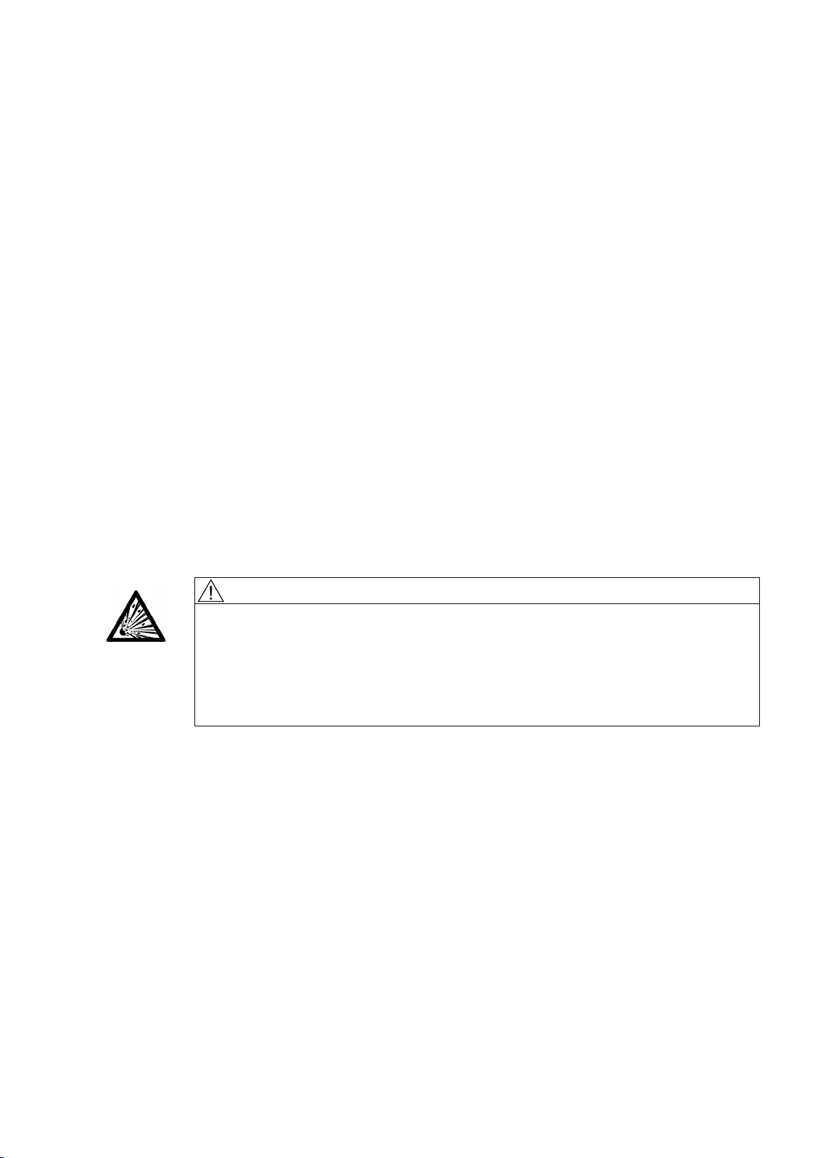
Danger due to bursting of the coupling
There is a risk of fatal injury from flying fragments. Bursting of the coupling can lead to an
explosion in potentially explosive atmospheres.
● Switch off the unit at once if any malfunctions occur.
● Note during the maintenance work the possible causes of faults and the notes on rectifying
them.
Proceed as described below if there is a malfunction of the coupling during operation:
1. De-energise the drive immediately.
2. Initiate the required action for repair, taking into consideration the applicable safety
regulations.
If you cannot determine the cause or if you cannot carry out repair work with your own means,
request one of our customer service technicians.
7.2.2 Identifying the fault cause
Faults occur frequently due to application errors or they occur due to operational circumstances
such as wear of wearing parts or changes to the system.
N-EUPEX / N-EUPEX DS 3100en
Operating Instructions 10/2017 37
Page 38

Operation
7.2 Faults - causes and rectification
The faults and fault causes listed below only serve as an indication for troubleshooting. In the
case of a complex system be sure to include all the system components in the search for the
fault.
WARNING
Physical injury
Injury from rotating parts.
● Only carry out work on the coupling when it is not moving.
● Secure the drive unit against being operated accidentally.
● Attach a notice to the switch stating clearly that work is being carried out on the coupling.
● Before starting any work, make sure that the unit is free from loads.
Intended use
The coupling is only approved for the applications specified in these instructions. Please
observe all the stipulations in section Intended use (Page 13).
7.2.2.1 Possible faults
Table 7-1 Table of faults
Fault Cause Rectification
Sudden changes in the noise level and/
or sudden occurrences of shocks
Wear of wearing parts Follow the instructions given in section
Replacing wearing parts (Page 40).
Changed alignment Follow the instructions given in section
Correcting the changed alignment
(Page 41).
Coupling not suitable for the operating
conditions.
Check the possible causes given in sec‐
tion Unsuitable coupling (Page 39).
Incorrect assembly of the coupling.
Check the possible causes given in sec‐
tions Assembly-related causes
(Page 39) and Specific installation-rela‐
ted and maintenance-related causes
(Page 40).
Incorrect maintenance of the coupling.
Check the possible causes given in sec‐
tions Maintenance-related causes
(Page 40) and Specific installation-rela‐
ted and maintenance-related causes
(Page 40).
Use a coupling that is suitable for the
operating conditions.
Reassemble the coupling in accordance
with these instructions.
Please observe all the stipulations and
requirements given in chapter Assem‐
bly (Page 23).
Please observe all the stipulations and
requirements given in chapter Servic‐
ing (Page 43).
N-EUPEX / N-EUPEX DS 3100en
38 Operating Instructions 10/2017
Page 39

7.2 Faults - causes and rectification
Fault Cause Rectification
Presence of vibration Coupling not suitable for the operating
conditions.
Check the possible causes given in sec‐
tion Unsuitable coupling (Page 39).
Incorrect assembly of the coupling.
Check the possible causes given in sec‐
tions Assembly-related causes
(Page 39) and Specific installation-rela‐
ted and maintenance-related causes
(Page 40).
Incorrect maintenance of the coupling.
Check the possible causes given in sec‐
tions Maintenance-related causes
(Page 40) and Specific installation-rela‐
ted and maintenance-related causes
(Page 40).
Use a coupling that is suitable for the
operating conditions.
Reassemble the coupling in accordance
with these instructions.
Please observe all the stipulations and
requirements given in chapter Assem‐
bly (Page 23).
Please observe all the stipulations and
requirements given in chapter Servic‐
ing (Page 43).
7.2.2.2 Possible causes
Operation
Unsuitable coupling
● Important information on the description of the drive unit and the environment were not
● System torque too high and/or torque dynamics not permissible.
● System speed too high.
● Application factor not selected correctly.
● Chemically aggressive environment not taken into consideration.
● Coupling not suitable for the ambient temperature.
● Diameter and/or assigned fit of the finished bore not permissible.
● Width across corners of the parallel keyways greater than the width across corners of the
● Shaft-hub connection incorrectly sized.
● Maximum permissible load conditions not taken into consideration.
● Maximum permissible overload conditions not taken into consideration.
● Dynamic load conditions not taken into consideration.
● Coupling and the machine and/or drive train form a critical torsional, axial or bending
available when the coupling was chosen.
parallel keyways in accordance with DIN 6885/1 for the maximum permissible bore.
vibration system.
Assembly-related causes
● Damaged parts installed.
● Shaft diameter outside the stipulated tolerance range.
N-EUPEX / N-EUPEX DS 3100en
Operating Instructions 10/2017 39
Page 40

Operation
7.2 Faults - causes and rectification
● Coupling parts interchanged and hence not assigned to the specified shaft.
● Stipulated locking elements to prevent axial movements not installed.
● Stipulated tightening torques not adhered to.
● Bolts inserted dry or greased.
● Flange surfaces of screwed connections not cleaned.
● Alignment and/or shaft misalignment values not set in accordance with the instructions.
● Coupled machines were not correctly connected to the foundation so that a shifting of the
machines leads to an impermissible displacement of the coupling parts.
● Coupled machines not earthed adequately.
● Coupling guard used is not suitable.
Maintenance-related causes
● Stipulated maintenance intervals not adhered to.
● Spare parts that were used were not original spare parts from Flender.
● Flender spare parts that were used were old or damaged.
● Leak in the area of the coupling not detected so that chemically aggressive substances
damage the coupling.
● Indications of faults, such as noise or vibration, were not heeded.
● Stipulated tightening torques not adhered to.
● Alignment and/or shaft misalignment values not set in accordance with the instructions.
Specific installation-related and maintenance-related causes
● Flexible elements (12) not fitted.
● Fitted flexible elements (12) heated up excessively when applying heat to the coupling parts.
● Flexible elements (12) are of different types or age.
● Flexible elements (12) not replaced as sets.
7.2.3 Correcting faults
7.2.3.1 Replacing wearing parts
Flexible elements (12) are subject to wear and this wear can result in torsional backlash.
N-EUPEX / N-EUPEX DS 3100en
40 Operating Instructions 10/2017
Page 41

Procedure
1. Check the wear on the flexible elements (12) (see section Maximum permissible torsional
backlash (Page 44)).
2. Replace the flexible elements (12) if necessary (see section Replacing wearing parts
(Page 45)).
7.2.3.2 Correcting the changed alignment
A changed alignment of the coupling during operation often occurs when the coupled machines
shift towards one another. A cause of this can be loose foundation bolts.
Procedure
1. Correct the cause for the change in alignment.
2. Check the wearing parts for wear and replace them as required.
3. Check the locking elements that prevent axial movements and correct these as required.
4. Realign the coupling.
Operation
7.2 Faults - causes and rectification
N-EUPEX / N-EUPEX DS 3100en
Operating Instructions 10/2017 41
Page 42

Operation
7.2 Faults - causes and rectification
N-EUPEX / N-EUPEX DS 3100en
42 Operating Instructions 10/2017
Page 43

Servicing
8.1 Maintenance intervals
DANGER
Danger due to bursting of the coupling
The coupling can burst if the maintenance intervals are not adhered to. There is a risk of fatal
injury from flying fragments. Bursting of the coupling can lead to an explosion in potentially
explosive atmospheres.
● Please observe all the stipulations concerning maintenance of the coupling in this section.
DANGER
Danger due to bursting of the coupling
The coupling can burst if the maximum permitted torsional backlash is exceeded. There is a
risk of fatal injury from flying fragments. Bursting of the coupling can lead to an explosion in
potentially explosive atmospheres.
● Note also the actual wear of the elastomer components.
8
WARNING
Physical injury
Injury from rotating parts.
● Only carry out work on the coupling when it is not moving.
● Secure the drive unit against being operated accidentally.
● Attach a notice to the switch stating clearly that work is being carried out on the coupling.
● Before starting any work, make sure that the unit is free from loads.
Check the torsional backlash between the coupling parts at the specified maintenance
intervals. The maximum permissible torsional backlash for the various coupling sizes can be
found in section Maximum permissible torsional backlash (Page 44).
Table 8-1 Maintenance intervals
Type Initial maintenance Follow-up maintenance
A 3 months after commissioning Every 12 months
B
ADS 3 months after commissioning
BDS
1)
According to the ATEX Directive, need only be inspected if a failure of the flexible elements (12) and
shutdown of the drive as a result of this failure could give rise to a risk of explosion. We recommend
that the torsional backlash is checked regularly.
1)
Every 12 months
1)
N-EUPEX / N-EUPEX DS 3100en
Operating Instructions 10/2017 43
Page 44

ෙ6
9
Servicing
8.2 Maximum permissible torsional backlash
Note
Shorter maintenance intervals
If necessary, set shorter maintenance intervals depending on actual wear.
8.2 Maximum permissible torsional backlash
In order to calculate the torsional backlash, rotate one coupling part without applying torque
up to the stop. Mark both of the coupling halves in the way shown in the diagram below. Turn
the coupling part in the opposite direction up to the stop. The markings on both halves will then
move apart. The distance between the markings corresponds to the torsional backlash.
Figure 8-1 Markings for calculating the torsional backlash
Table 8-2 Maximum permissible torsional backlash for the types A and B (sizes 58 to 250)
Size 58 68 80 95 110 125 140 160 180 200 225 250
Maximum permissible
torsional backlash ΔS
[mm]
Table 8-3 Maximum permissible torsional backlash for the types A and B (sizes 280 to 710)
Size 280 315 350 400 440 480 520 560 610 660 710
Maximum permissible
torsional backlash ΔS
[mm]
Table 8-4 Maximum permissible torsional backlash for the types ADS and BDS (sizes 66 to 218)
Size 66 76 88 103 118 135 152 172 194 218
Maximum permissible
torsional backlash ΔS
[mm]
5.5 5.5 5.0 6.0 7.0 8.0 8.0 8.0 8.0 8.5 9.0 10.0
V
11.5 10.5 11.5 13.0 14.0 15.5 17.5 17.5 19.5 21.0 22.5
V
6.0 7.0 5.0 7.0 9.0 10.5 11.5 9.0 8.0 7.0
V
N-EUPEX / N-EUPEX DS 3100en
44 Operating Instructions 10/2017
Page 45

Table 8-5 Maximum permissible torsional backlash for the types ADS and BDS (sizes 245 to 556)
Size 245 272 305 340 380 430 472 514 556
Maximum permissible
torsional backlash ΔS
[mm]
6.5 7.0 8.0 6.5 7.0 10.0 12.0 14.0 16.0
V
8.3 Replacing wearing parts
DANGER
Danger due to bursting of the coupling
If you do not observe the information stipulated here regarding replacement of wearing parts,
this can lead to bursting of the coupling during operation. There is a risk of fatal injury from
flying fragments. Bursting of the coupling can lead to an explosion in potentially explosive
atmospheres.
● Please observe all the stipulations concerning the replacement of wearing parts.
Servicing
8.3 Replacing wearing parts
Types A and ADS
Replace the flexible elements (12) if the maximum permissible torsional backlash has been
reached. The method used to replace the flexible elements (12) varies according to the
coupling type.
Replace the flexible elements (12) without moving the coupled machines.
1. Undo the connection between coupling parts 2 (2) and 3 (3).
2. Move the coupling part 3 (3) axially.
The flexible elements (12) are freely accessible after coupling part 2 (2) has been turned.
Note
Loosening coupling part 3 (3)
To make it easier to loosen coupling part 3 (3), a tapped jacking hole is machined in coupling
part 1 (1) on coupling sizes 225 to 430. As of coupling size 440, the tapped jacking hole is
machined in coupling part 3 (3).
① Tapped jacking hole in coupling part 1
② Tapped jacking hole in coupling part 3
Figure 8-2 Tapped jacking hole for loosening coupling part 3 (3)
N-EUPEX / N-EUPEX DS 3100en
Operating Instructions 10/2017 45
Page 46

Servicing
8.4 Removing the coupling
3. Remove the flexible elements (12).
4. Install the new flexible elements (12).
Please observe the information in section Use and storage of flexible elements (12)
(Page 64) when replacing flexible elements (12).
When reinstalling the coupling parts please observe the information in chapters Assembly
(Page 23) and Commissioning (Page 35).
Types B and BDS
1. In order to replace the flexible elements (12), move the coupled machines apart.
2. Remove the flexible elements (12).
3. Install the new flexible elements (12).
Please observe the information in section Use and storage of flexible elements (12)
(Page 64) when replacing flexible elements (12).
When reinstalling the coupling parts please observe the information in chapters Assembly
(Page 23) and Commissioning (Page 35).
8.4 Removing the coupling
DANGER
Danger from burners and hot coupling parts
Risk of injury due to burners and hot surfaces. Burners or hot coupling parts can lead to an
explosion in potentially explosive atmospheres.
● Wear suitable protective equipment (gloves, safety goggles).
● Ensure that the area is not at risk of explosion.
Procedure
1. Move the coupled machines apart.
2. Secure the coupling parts to prevent them from falling.
3. Remove the axial locking elements (set screw, end plate).
4. Use a suitable pulling fixture.
5. Heat up the coupling part 1 (1) and 2 (2) or 4 (4) using a burner above the parallel keyway
along its length to maximum 80 °C.
Note when doing this the temperature range of the flexible elements (12) (see sections NEUPEX flexible elements (12) (Page 65)and N-EUPEX DS flexible elements (12)
(Page 66)). Remove the flexible elements if necessary.
6. Pull off the coupling part. Use suitable lifting gear when doing this.
7. Check the hub bore and the shaft for damage and protect them against corrosion.
8. Replace any damaged parts.
N-EUPEX / N-EUPEX DS 3100en
46 Operating Instructions 10/2017
Page 47

Servicing
8.4 Removing the coupling
When reinstalling the coupling parts please observe the information in chapters Assembly
(Page 23) and Commissioning (Page 35).
N-EUPEX / N-EUPEX DS 3100en
Operating Instructions 10/2017 47
Page 48

Servicing
8.4 Removing the coupling
N-EUPEX / N-EUPEX DS 3100en
48 Operating Instructions 10/2017
Page 49

Service and support
9.1 Contact
Contact
When ordering spare parts, requesting a customer service technician or in the case of technical
queries, please contact our factory or one of our customer service addresses:
Flender GmbH
Schlavenhorst 100
46395 Bocholt
Germany
Tel.: +49 (0)2871/92-0
Fax.: +49 (0)2871/92-2596
9
N-EUPEX / N-EUPEX DS 3100en
Operating Instructions 10/2017 49
Page 50

Service and support
9.1 Contact
N-EUPEX / N-EUPEX DS 3100en
50 Operating Instructions 10/2017
Page 51

Disposal
Disposal of the coupling
Dispose of the coupling parts according to applicable national regulations or recycle them.
10
N-EUPEX / N-EUPEX DS 3100en
Operating Instructions 10/2017 51
Page 52

Disposal
N-EUPEX / N-EUPEX DS 3100en
52 Operating Instructions 10/2017
Page 53

Spare parts
11.1 Ordering spare parts
By stocking the most important spare parts at the installation site you can ensure that the
coupling is ready for use at any time.
Note
Original spare parts
Only use original spare parts from Flender. Flender only accepts liability for original spare parts
from Flender.
Other spare parts are not tested and approved by Flender. Non-approved spare parts may
possibly change the design characteristics of the coupling and thus impact active and/or
passive safety.
Flender will accept no liability or warranty whatsoever for damage occurring as a result of the
use of non-approved spare parts. The same applies to any accessories that were not supplied
by Flender.
You can find the available spare parts for the coupling described here at Spare parts drawing
and spare parts list (Page 54).
11
You will find our contact data for ordering spare parts in Service and support (Page 49).
Information required when ordering spare parts
● Flender order number with item
● Flender drawing number
● Coupling type and size
● Part number (refer to Spare parts drawing and spare parts list (Page 54))
● Dimensions of the pare part, for example:
– Bore
– Bore tolerance
– Parallel keyway and balancing
● Special dimensions, for example, flange connection dimensions, intermediate sleeve length
or brake drum dimensions
N-EUPEX / N-EUPEX DS 3100en
Operating Instructions 10/2017 53
Page 54

Spare parts
11.2 Spare parts drawing and spare parts list
● Any special properties of the spare part, such as, for example:
– Temperature resistance
– Electrical insulation
– Operating fluid
– Use in potentially explosive atmospheres
● Quantity
11.2 Spare parts drawing and spare parts list
11.2.1 Types A and ADS
54 Operating Instructions 10/2017
Figure 11-1 Spare parts drawing for types A and ADS
Table 11-1 Spare parts list for types A and ADS
Part number Designation
1 Coupling part 1
2 Coupling part 2
3 Coupling part 3
12 Flexible element
13 Cylinder-head screw
16 Cylindrical pin
only with type A sizes 560 to 710
N-EUPEX / N-EUPEX DS 3100en
Page 55

11.2.2 Types B and BDS
Figure 11-2 Spare parts drawing for types B and BDS
Table 11-2 Spare parts list for types B and BDS
Part number Designation
1 Coupling part 1
4 Coupling part 4
12 Flexible element
Spare parts
11.2 Spare parts drawing and spare parts list
N-EUPEX / N-EUPEX DS 3100en
Operating Instructions 10/2017 55
Page 56

Spare parts
11.2 Spare parts drawing and spare parts list
N-EUPEX / N-EUPEX DS 3100en
56 Operating Instructions 10/2017
Page 57

Technical data
6
'
1'
'$
'
1'
88
3
1/1/
A.1 Speeds, geometry data and weights
In this section you can find dimension drawings and technical data for N‑EUPEX and
N‑EUPEX DS couplings of the following types:
● Type A (Page 57)
● Type B (Page 59)
● Type ADS (Page 60)
● Type BDS (Page 61)
A.1.1 Type A
A
1 Coupling part 1
2 Coupling part 2
3 Coupling part 3
Figure A-1 Type A
Table A-1 Speeds, geometry data and weights of type A
Size
110 5 300 48 38 110 86 62 40 2 … 4 34 20 33 3
125 5 100 55 45 125 100 75 50 2 … 4 36 23 38 4.8
140 4 900 60 50 140 100 82 55 2 … 4 34 28 43 6
160 4 250 65 58 160 108 95 60 2 … 6 39 28 47 8.4
180 3 800 75 65 180 125 108 70 2 … 6 42 30 50 12
N-EUPEX / N-EUPEX DS 3100en
Operating Instructions 10/2017 57
Speed
n
max
rpm
Maximum bore
D1
mm
1)
D2
mm
DA
mm
ND1
mm
ND2
mm
NL1 / NL2
mm
S
mm
U1
mm
U2
mm
P
mm
Weight
m
kg
2)
Page 58

Technical data
A.1 Speeds, geometry data and weights
D2
mm
1)
DA
mm
ND1
mm
ND2
mm
NL1 / NL2
mm
S
mm
U1
mm
U2
mm
P
mm
Size
Speed
n
max
rpm
Maximum bore
D1
mm
200 3 400 85 75 200 140 122 80 2 … 6 47 32 53 17
225 3 000 90 85 225 150 138 90 2 … 6 52 38 61 23
250 2 750 100 95 250 165 155 100 3 … 8 60 42 69 31
280 2 450 110 105 280 180 172 110 3 … 8 65 42 73 41
315 2 150 100
120
350 2 000 110
140
400 1 700 120
150
440 1 550 130
160
480 1 400 145
180
520 1 300 150
190
100
120
110
140
120
150
130
160
145
180
150
190
315 165
200
350 180
230
400 200
250
440 215
265
480 240
300
520 250
315
165
200
180
230
200
250
215
265
240
300
250
315
125 3 … 8 70 47 78 57
140 3 … 8 74 51 83 78
160 3 … 8 78 56 88 112
180 5 … 10 86 64 99 147
190 5 … 10 90 65 104 184
210 5 … 10 102 68 115 234
560 1 200 200 200 560 320 320 220 6 … 12 115 80 125 329
610 1 100 220 220 610 352 352 240 6 … 12 121 88 135 416
660 1 000 240 240 660 384 384 260 6 … 12 132 96 145 546
710 1 000 260 260 710 416 416 290 6 … 12 138 102 155 680
1)
Maximum bore for parallel keyway in accordance with DIN 6885/1.
2)
Weight applies to one coupling with maximum bore.
Weight
m
kg
61
82
117
155
200
254
2)
N-EUPEX / N-EUPEX DS 3100en
58 Operating Instructions 10/2017
Page 59

A.1.2 Type B
1/1/
'
1'
'$
'
1'
8
6
8
1 Coupling part 1
4 Coupling part 4
Figure A-2 Type B
Technical data
A.1 Speeds, geometry data and weights
Table A-2 Speeds, geometry data and weights of type B
D2
mm
1)
DA
mm
ND1
mm
ND2
mm
NL1 / NL2
mm
S
mm
U1
mm
U2
mm
Size Speed
n
max.
rpm
Maximum bore
D1
mm
58 7 500 19 24 58 58 40 20 2 … 4 20 8 0.4
68 7 000 24 28 68 68 50 20 2 … 4 20 8 0.54
80 6 000 30 38 80 80 68 30 2 … 4 30 10 1.3
95 5 500 42 42 95 76 76 35 2 … 4 30 12 2.2
110 5 300 48 48 110 86 86 40 2 … 4 34 14 3.3
125 5 100 55 55 125 100 100 50 2 … 4 36 18 5.2
140 4 900 60 60 140 100 100 55 2 … 4 34 20 5.6
160 4 250 65 65 160 108 108 60 2 … 6 39 20 7.8
180 3 800 75 75 180 125 125 70 2 … 6 42 20 11.5
200 3 400 85 85 200 140 140 80 2 … 6 47 24 16
225 3 000 90 90 225 150 150 90 2 … 6 52 18 20
250 2 750 100 100 250 165 165 100 3 … 8 60 18 29
280 2 450 110 110 280 180 180 110 3 … 8 65 20 38
1)
Maximum bore for parallel keyway in accordance with DIN 6885/1.
2)
Weight applies to one coupling with maximum bore.
Weight
m
kg
2)
N-EUPEX / N-EUPEX DS 3100en
Operating Instructions 10/2017 59
Page 60

88
3
1/1/
'
1'
'$
'
1'
6
Technical data
A.1 Speeds, geometry data and weights
A.1.3 Type ADS
1 Coupling part 1
2 Coupling part 2
3 Coupling part 3
Figure A-3 Type ADS
Table A-3 Speeds, geometry data and weights of type ADS
D2
mm
1)
DA
mm
ND1
mm
ND2
mm
NL1 / NL2
mm
S
mm
U1
mm
U2
mm
P
mm
Size Speed
n
max.
rpm
Maximum bore
D1
mm
118 5 300 48 38 118 86 62 40 2 … 4 34 20 33 3.5
135 5 100 55 45 135 100 75 50 2 … 4 36 23 38 5.5
152 4 900 60 50 152 108 82 55 2 … 4 36 28 43 7.7
172 4 250 65 58 172 118 95 60 2 … 6 41 28 47 10.5
194 3 800 75 65 194 135 108 70 2 … 6 44 30 50 15
218 3 400 85 75 218 150 122 80 2 … 6 47 32 53 21
245 3 000 90 85 245 150 138 90 2 … 6 52 38 61 28
272 2 750 100 95 272 165 155 100 3 … 8 60 42 69 40
305 2 450 110 105 305 180 172 110 3 … 8 65 42 73 50
340 2 150 120 100
120
380 2 000 140 110
140
430 1 700 150 120
150
472 1 550 160 130
160
340 200 165
200
380 230 180
230
430 250 200
250
472 265 215
265
125 3 … 8 70 47 78 72
140 3 … 8 74 51 83 100
160 3 … 8 78 56 88 135
180 5 … 10 86 64 99 174
Weight
m
kg
73
104
140
180
2)
N-EUPEX / N-EUPEX DS 3100en
60 Operating Instructions 10/2017
Page 61

8
8
1/1/
'
1'
'$
'
1'
6
Technical data
A.1 Speeds, geometry data and weights
D2
mm
180
190
1)
DA
mm
514 300 240
556 315 250
ND1
mm
ND2
mm
300
315
Size Speed
n
max.
rpm
Maximum bore
D1
mm
514 1 400 180 145
556 1 300 190 150
1)
Maximum bore for parallel keyway in accordance with DIN 6885/1.
2)
Weight applies to one coupling with maximum bore.
A.1.4 Type BDS
NL1 / NL2
mm
S
mm
U1
mm
U2
mm
P
mm
190 5 … 10 90 65 104 220
210 5 … 10 102 68 115 281
Weight
m
kg
237
290
2)
1 Coupling part 1
4 Coupling part 4
Figure A-4 Type BDS
Table A-4 Speeds, geometry data and weights of type BDS
Size Speed
n
max.
rpm
Maximum bore
D1
mm
D2
mm
1)
DA
mm
ND1
mm
ND2
mm
NL1 / NL2
mm
S
mm
U1
mm
U2
mm
Weight
m
kg
2)
66 7 500 19 24 66 66 40 20 2 … 4 20 8 0.5
76 7 000 24 28 76 76 50 20 2 … 4 20 8 0.65
88 6 000 30 38 88 88 68 30 2 … 4 30 10 1.8
103 5 500 42 42 103 76 76 35 2 … 4 30 12 3
118 5 300 48 48 118 86 86 40 2 … 4 34 14 3.7
135 5 100 55 55 135 100 100 50 2 … 4 36 18 6.1
152 4 900 60 60 152 108 100 55 2 … 4 36 20 7
172 4 250 65 65 172 118 108 60 2 … 6 41 20 11
194 3 800 75 75 194 135 125 70 2 … 6 44 20 17
N-EUPEX / N-EUPEX DS 3100en
Operating Instructions 10/2017 61
Page 62

Technical data
A.2 Shaft misalignment values during operation
D2
mm
1)
DA
mm
ND1
mm
ND2
mm
NL1 / NL2
mm
S
mm
U1
mm
U2
mm
Weight
Size Speed
n
max.
rpm
Maximum bore
D1
mm
218 3 400 85 85 218 150 140 80 2 … 6 47 24 23
245 3 000 90 90 245 150 150 90 2 … 6 52 18 27
272 2 750 100 100 272 165 165 100 3 … 8 60 18 36
305 2 450 110 110 305 180 180 110 3 … 8 65 20 47
1)
Maximum bore for parallel keyway in accordance with DIN 6885/1.
2)
Weight applies to one coupling with maximum bore.
A.2 Shaft misalignment values during operation
The following table shows the maximum permissible shaft misalignment values ΔS
ΔKr
. The values are rounded and specified in mm.
perm
Table A-5 Maximum permissible shaft misalignment values during operation
Type / size Coupling speed [rpm]
A, B ADS, BDS 250 500 750 1 000 1 500 2 000 3 000 4 000 5 000
58
68
80
95
110
125
140
160
180
200
225
250
280
315
350
400
440
480
520
560
610
660
710
66
76
88
103
118
135
152
172
194
218
245
272
305
340
380
430
472
514
0.4
0.4
0.4
0.5
0.5
0.5
0.6
0.6
0.6
0.8
0.8
0.8
1
1
1
1.2
1.3
1.4
556 1.5
1.6
1.8
1.9
2
0.3
0.3
0.3
0.35
0.35
0.4
0.4
0.5
0.5
0.55
0.55
0.6
0.7
0.7
0.8
0.9
1
1
1.1
1.2
1.3
1.4
1.5
0.25
0.25
0.25
0.25
0.3
0.3
0.35
0.4
0.4
0.45
0.5
0.5
0.6
0.6
0.6
0.7
0.7
0.8
0.9
1
1
1.1
1.2
0.2
0.2
0.2
0.25
0.25
0.25
0.3
0.35
0.35
0.4
0.4
0.4
0.5
0.5
0.6
0.6
0.7
0.2
0.2
0.2
0.2
0.2
0.25
0.25
0.3
0.3
0.3
0.35
0.35
0.4
0.4
0.5
0.5
0.6
0.15
0.15
0.15
0.2
0.2
0.2
0.2
0.25
0.25
0.3
0.3
0.15
0.15
0.15
0.15
0.15
0.15
0.2
0.2
0.2
0.2
0.25
0.3
0.35
0.35
0.7
0.8
0.8
0.9
1
perm
0.1
0.1
0.1
0.1
0.1
0.15
0.15
0.15
2)
m
kg
and
0.1
0.1
0.1
0.1
0.1
0.1
N-EUPEX / N-EUPEX DS 3100en
62 Operating Instructions 10/2017
Page 63

Technical data
A.3 Tightening torques and widths A/F
You can calculate the numerical values in the table and their intermediate values as follows:
ΔKr
perm
= ΔS
= (0.1 + DA / 1000) · 40 / √n Coupling speed n in rpm
perm
The values in column "250 rpm" of the table above apply for speeds of < 250 rpm.
A.3 Tightening torques and widths A/F
Table A-6 Tightening torques for part 13 of types A and ADS
N‑EUPEX-
Coupling
Size
110 118 14 6
125 135 17.5 6
140 152 29 8
160 172 35 8
180 194 44 8
200 218 67.5 10
225 245 86 10
250 272 145 14
280 305 185 14
315 340 200 14
350 380 260 17
400 430 340 17
440 472 410 17
480 514 550 19
520 556 670 19
560 - 710 19
610 - 1 450 22
660 - 1 450 22
710 - 1 450 22
N‑EUPEX DS-
Coupling
Size T
Hexagon socket-head screws according to DIN EN ISO 4762
DA in mm (see Speeds, geometry data and
weights (Page 57))
Radial misalignment ΔKr
Tightening torque TA and width A/F SW for
A
Nm
perm
in mm
SW
mm
Apply the recommended tightening torques in accordance with the stipulations in section
Tightening procedure (Page 64).
N-EUPEX / N-EUPEX DS 3100en
Operating Instructions 10/2017 63
Page 64

Technical data
A.4 Tightening procedure
A.4 Tightening procedure
Tighten fastening screws to the specified tightening torque in accordance with the following
table:
Table A-7 Tightening procedure
Scatter of the torque applied
at the tool
±5 %
Tightening procedure
(As a rule, the tightening procedures listed are within the specified tool
torque scatter)
● Hydraulic tightening with mechanical screwdriver
● Torque-controlled tightening with a torque wrench or a torque
wrench that gives a signal
● Tightening with a precision mechanical screwdriver with dynamic
torque measurement
The tightening torques apply to screws/bolts with untreated surfaces that are not oiled or are
only lightly oiled, and for screws/bolts that are used with a liquid screw locking agent in
accordance with these instructions. Use with lubricant paint or lubricant is not permitted.
A.5 Flexible elements (12)
A.5.1 Use and storage of flexible elements (12)
Note the following concerning the use and storage of the flexible elements (12):
● Storage possible for up to 5 years
● Protect against direct sunlight, artificial light with a high UV‐content and extreme
temperatures
● Avoid contact with aggressive media
● Only replace complete sets
● Only use flexible elements of the same type and age
N-EUPEX / N-EUPEX DS 3100en
64 Operating Instructions 10/2017
Page 65

A.5.2 N-EUPEX flexible elements (12)
Table A-8 N‑EUPEX flexible elements
Technical data
A.5 Flexible elements (12)
Material Hardness Comment Marking Ambient tempera‐
ture
NBR 80 Shore A Standard Black flexible elements
with
blue stripe
NBR 65 Shore A Special, soft,
shifting of the
resonant speed,
rated torque
reduced
NBR 90 Shore A Special, hard,
shifting of the
resonant speed
NBR 80 Shore A Special,
increased (low-backlash)
NBR 65 Shore A Special,
increased (low-backlash)
shifting of the
resonant speed,
rated torque
reduced
NR 80 Shore A Special,
low-temperature use
HNBR 80 Shore A Special,
high-temperature use
NBR 80 Shore A Special,
electrically insulating
Black flexible elements
with
green stripe
Black flexible elements
with
magenta stripe
Black flexible elements
with
yellow stripe
Black flexible elements
with
white stripe
Black flexible elements
with
orange
stripe
Black flexible elements
with
red stripe
Green flexible ele‐
ments
-30 °C to +80 °C IIA, IIB, IIC
-30 °C to +80 °C IIA, IIB, IIC
-30 °C to +80 °C IIA, IIB, IIC
-30 °C to +80 °C IIA, IIB, IIC
-30 °C to +80 °C IIA, IIB, IIC
-50 °C to +50 °C IIA, IIB, IIC
-10 °C to +100 °C Not approved
-30 °C to +80 °C IIA, IIB
Approved for
explosion group
N-EUPEX / N-EUPEX DS 3100en
Operating Instructions 10/2017 65
Page 66

Technical data
A.5 Flexible elements (12)
A.5.3 N-EUPEX DS flexible elements (12)
Table A-9 N‑EUPEX DS flexible elements
Material Hardness Comment Marking Ambient tempera‐
ture
NBR 80/90 Shore A Standard,
2 components
Sizes 66 … 272
NBR 90 Shore A Standard,
sizes 305 … 556
PU 95 Shore A Special,
electrically insulating
Black flexible elements -30 °C to +80 °C IIA, IIB, IIC
Black flexible elements -30 °C to +80 °C IIA, IIB, IIC
Blue flexible elements /
green flexible elements
-30 °C to +50 °C IIA, IIB
Approved for
explosion group
N-EUPEX / N-EUPEX DS 3100en
66 Operating Instructions 10/2017
Page 67

Quality documents
B.1 Declaration of Conformity
B
N-EUPEX / N-EUPEX DS 3100en
Operating Instructions 10/2017 67
Page 68

EU declaration of conformity
Product:
FLENDER N-EUPEX® and
FLENDER N-EUPEX-DS®
couplings
Types A, B and ADS, BDS
Name and address of the manufacturer:
Flender GmbH
Schlavenhorst 100
46395 Bocholt
Deutschland – Germany
This declaration of conformity is issued under the sole responsibility of the manufacturer.
Object of the declaration is the product specified above.
The object of the declaration described above is in conformity with the relevant harmonisation
legislation of the Union:
– Directive 2014/34/EU Official Journal L 96, 29.3.2014, pages 309-356
Harmonised standards or other technical specifications, on which the declaration of conformity is
based:
EN 1127‐1 : 2011
EN 1710 : 2008
EN 13463‐1 : 2009
EN 13463‐5 : 2011
The notified body, DEKRA EXAM GmbH, code number 0158, has received the technical
documentation.
Signed for and on behalf of:
Flender GmbH
Bocholt, 2017-10-01 i.V.
Felix Henseler, Head of PD MD AP
Bocholt, 2017-10-01 i.V.
Thomas Tebrügge, Head of PD MD AP COU BA
Quality documents
B.1 Declaration of Conformity
N-EUPEX / N-EUPEX DS 3100en
68 Operating Instructions 10/2017
Page 69

AA 3100_KE_en_FLE
Page 70

FLENDER COUPLINGS
N-EUPEX / N-EUPEX DS
Operating Instructions 3100en
Edition 10/2017
Flender GmbH
Alfred-Flender-Straße 77
46395 Bocholt
GERMANY
 Loading...