

Fleck 5600, ECONOMINDER 5600 Service Manual
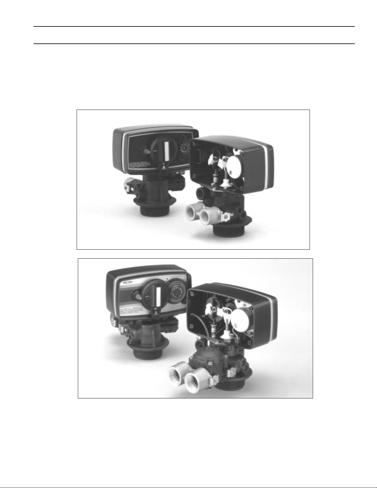
MODEL 5600 & 5600 ECONOMINDER
Service Manual
®
IMPORTANT: Fill in pertinent information on page 2 for future reference.

MODEL 5600 & 5600 ECONOMINDER
Job Specification Sheet
• JOB NO. __________________________________________________________
• *MODEL NO. ______________________________________________________
• WATER TEST ______________________________________________________
• CAPACITY PER UNIT_____________MAX. ___________PER REG ENERATION
• MINERAL TANK SIZE DIA.________HEIGHT _________
• BRINE TANK SIZE & S ALT SETTING PER REGENERATION:
• _________________________________________________________________
CONTROL VALVE SPECIFICATIONS
Type of Timer
A) Std C) 7 Day E) Meter, Std.
®
B) “L” D) 12 Day F) Meter, Ext.
Day/Time of Regeneration____________________________________
Drain Line Flow Control______________________________________ gpm
Brine Refill Rate____________________________________________ gpm
Injector Size_______________________________________________
Meter Gallon Setting________________________________________ gal.
Tank Size
Dia. Injector
″
6
7
8
9
10
12
13
″
″
″
″
″
″
# 0 Red
# 0 Red
# 1 White
# 1 White
# 1 White
# 2 Blue
# 2 Blue
TYPICAL CONTROL VALVE INFORMATION
Slow Rinse
Rate (gpm)
@ 40 PSI
.31 gpm
.31 gpm
.45 gpm
.45 gpm
.45 gpm
.84 gpm
.84 gpm
Brine Draw
Rate (SPM)
@ 40 PSI
.28 gpm
.28 gpm
.38 gpm
.38 gpm
.38 gpm
.56 gpm
.56 gpm
B.L.F.C.
.5 gpm
.5 gpm
.5 gpm
.5 gpm
.5 gpm
1.0 gpm
1.0 gpm
1
D.L.F.C.
1.2 gpm
1.2 gpm
1.5 gpm
2.0 gpm
2.4 gpm
3.5 gpm
4.0 gpm
2
″
14
″
16
Due to varying water conditions, tank sizes and water pressures, the above settings should be used only as a
guideline.
1B.L.F.C. (Brine Line Flow Control). Refill Rate for Filling Brine Tank.
2
D.L.F.C. (Drain Line Flow Control). Backwash and Rapid Rinse Flow Rates.
# 3 Yellow
# 3 Yellow
1.0 gpm
1.0 gpm
.63 gpm
.63 gpm
1.0 gpm
1.0 gpm
5.0 gpm
7.0 gpm
Page 2
Printed in U.S.A.
MODEL 5600
Installation and Start-Up Procedure
The water softener should be installed with the inlet, outlet and drain connections made in accordance with
manufacturer’s recommendations and to meet applicable plumbing codes.
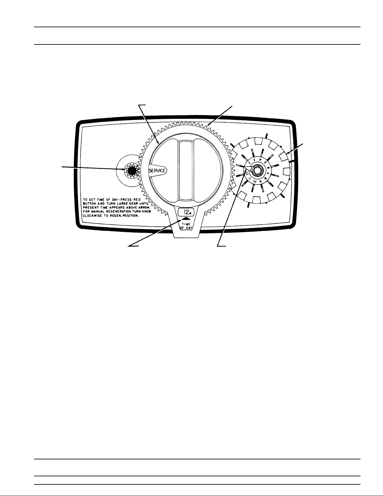
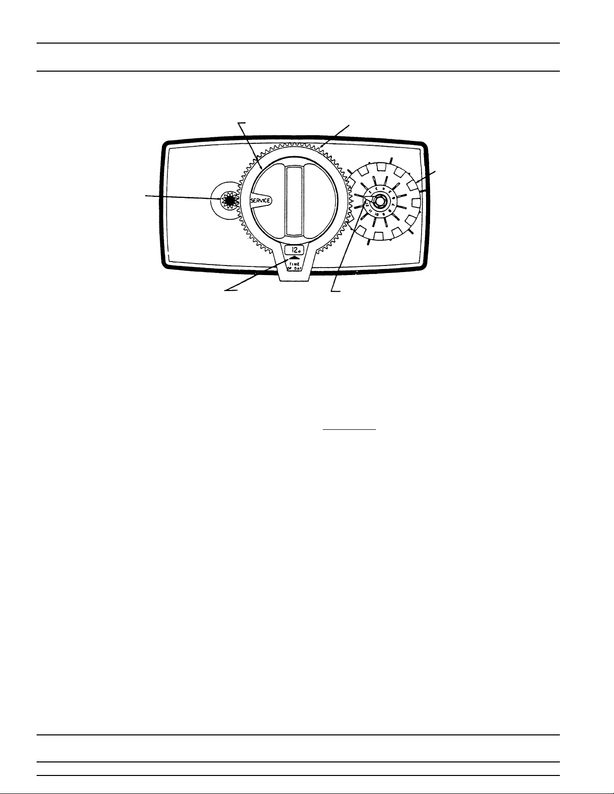
MANUAL
REGENERATION KNOB
RED TIME
SET
BUTTON
TIME OF DAY ARROW RED POINTER
1. Manually index the softener control into the service
position and let water flow into the resin tank. When
the water flow stops, open a softened water tap until
all air is released from the lines, then close the tap.
Note: the various regeneration positions may be
dialed manually by turning the knob on the front of the
control until the indicator shows that the softener is in
the desired position.
2. Manually index the control to the backwash position
and allow water to flow at the drain for 3 or 4 minutes.
3. Remove back cover plate.
4. Make sure that the salt dosage is set as
recommended by the manufacturer. If necessary, set
salt in accordance with the setting instruction sheet.
Manually index the control to the brine fill position and
allow the brine tank to fill to the top of the air check.
24 HOUR GEAR
SKIPPER WHEEL
(SHOWS EVERY
OTHER DAY
REGENERATION)
5. Manually index the control to the brine draw position
and allow the control to draw water from the brine
tank until it stops.
6. Plug in the electrical cord and look in the sight hole in
the back of the motor to see that it is running. Set the
days that regeneration is to occur by sliding tabs on
skipper wheel outward to expose trip fingers. Each
tab is one day. Finger at red pointer is tonight. Moving
clockwise from red pointer, extend or retract fingers to
obtain the desired regeneration schedule.
7. Manually advance the control to the beginning of the
brine fill position; and allow the control to return to the
service position automatically.
8. Fill the brine tank with salt.
9. Replace back cover on the control.
10. Make sure that any by-pass valving is left in the
normal service position.
Printed in U.S.A.
Page 3
MODEL 5600
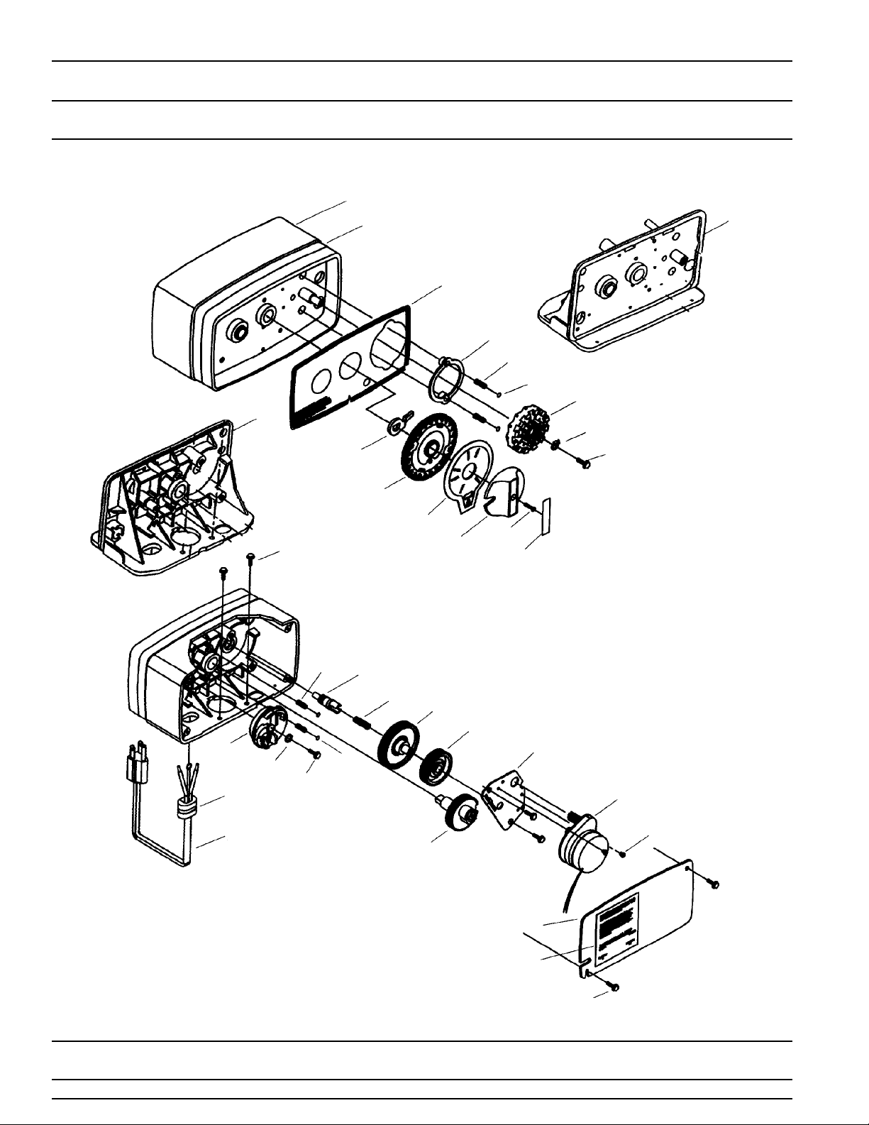
Control Valve Drive Assembly
(See opposite page for parts list)
1
29
1A
13
1A
27
20
16
15
19
22
5
30
25
23
35
34
12
38
14
21
7
8
5
6
11
37
39
9
2
3
4
Page 4
26
28
5
Printed in U.S.A.

MODEL 5600
Control Valve Drive Assembly
Parts List
Item No. Quantity Part No. Description
1. . . . . . . . . . . . 1 . . . . . . . . . . . . .14448-010 . . . . . . . . . . . . . . Housing - w/Pin
1 . . . . . . . . . . . . .14448-011 . . . . . . . . . . . . . . Housing - w/Pin Drilled for Screw
1 . . . . . . . . . . . . .14448-012 . . . . . . . . . . . . . . Housing - w/Pin Drilled for Thumb Screw
1A . . . . . . . . . . . 1 . . . . . . . . . . . . .15494-01 . . . . . . . . . . . . . . . “L” Housing - w/Pin
1 . . . . . . . . . . . . .15494-03 . . . . . . . . . . . . . . . “L” Housing - w/Pin Drilled for Designer
2. . . . . . . . . . . . 1 . . . . . . . . . . . . .13175. . . . . . . . . . . . . . . . . . Motor Mounting Plate
3. . . . . . . . . . . . 1 . . . . . . . . . . . . .18743. . . . . . . . . . . . . . . . . . Motor - 120V., 60 Hz.
1 . . . . . . . . . . . . .19659. . . . . . . . . . . . . . . . . . Motor - 24V., 60 Hz.
4. . . . . . . . . . . . (2-3) . . . . . . . . . .11384. . . . . . . . . . . . . . . . . . Screw - Motor Mtg. & Ground Wire
5. . . . . . . . . . . . (3-5) . . . . . . . . . .13296. . . . . . . . . . . . . . . . . . Screw - Component Mounting
6. . . . . . . . . . . . 1 . . . . . . . . . . . . .13017. . . . . . . . . . . . . . . . . . Idler Gear
7. . . . . . . . . . . . 1 . . . . . . . . . . . . .13018. . . . . . . . . . . . . . . . . . Idler Pinion
8. . . . . . . . . . . . 1 . . . . . . . . . . . . .13312. . . . . . . . . . . . . . . . . . Spring - Idler
9. . . . . . . . . . . . 1 . . . . . . . . . . . . .13164. . . . . . . . . . . . . . . . . . Drive Gear
11 . . . . . . . . . . . 1 . . . . . . . . . . . . . 13170. . . . . . . . . . . . . . . . . . Main Gear & Shaft
12 . . . . . . . . . . . 1 . . . . . . . . . . . . . 19205. . . . . . . . . . . . . . . . . . 24 Hour Gear Assembly, Silver
1 . . . . . . . . . . . . . 19205-01 . . . . . . . . . . . . . . . 24 Hour Gear Assy, Tan
13 . . . . . . . . . . . 1 . . . . . . . . . . . . . 13011. . . . . . . . . . . . . . . . . . Cycle Actuator Gear
14 . . . . . . . . . . . 1 . . . . . . . . . . . . .14177. . . . . . . . . . . . . . . . . . Knob - Manual Regeneration
15 . . . . . . . . . . . 4 . . . . . . . . . . . . .13300. . . . . . . . . . . . . . . . . . Ball - 1/4″ Dia.
16 . . . . . . . . . . . 2 . . . . . . . . . . . . .13311. . . . . . . . . . . . . . . . . . Spring - Detent - Skipper Wheel
19 . . . . . . . . . . . 1 . . . . . . . . . . . . .14381. . . . . . . . . . . . . . . . . . Skipper Wheel Assembly - 12 Day
1 . . . . . . . . . . . . .14860. . . . . . . . . . . . . . . . . . Skipper Wheel Assembly - 7 Day
20 . . . . . . . . . . . 1 . . . . . . . . . . . . .13864. . . . . . . . . . . . . . . . . . Skipper Wheel Ring
21 . . . . . . . . . . . 2 . . . . . . . . . . . . . 14457. . . . . . . . . . . . . . . . . . Spring - Detent - Main Gear
22 . . . . . . . . . . . 1 . . . . . . . . . . . . .13014. . . . . . . . . . . . . . . . . . Regeneration Pointer
23 . . . . . . . . . . . 1 . . . . . . . . . . . . .11842. . . . . . . . . . . . . . . . . . Electrical Cord - Standard
24 . . . . . . . . . . . 2 . . . . . . . . . . . . .12681. . . . . . . . . . . . . . . . . . Wire Connector (Not Shown)
25 . . . . . . . . . . . 1 . . . . . . . . . . . . .13547. . . . . . . . . . . . . . . . . . Strain Relief
26 . . . . . . . . . . . 1 . . . . . . . . . . . . .13229. . . . . . . . . . . . . . . . . . Back Cover
27 . . . . . . . . . . . 1 . . . . . . . . . . . . .13309. . . . . . . . . . . . . . . . . . Front Label - Brown on Beige
1 . . . . . . . . . . . . .13437. . . . . . . . . . . . . . . . . . Front Label - Blue/Silver on Black
28 . . . . . . . . . . . 1 . . . . . . . . . . . . .13310. . . . . . . . . . . . . . . . . . Rear Label - Softener
1 . . . . . . . . . . . . .18520. . . . . . . . . . . . . . . . . . Rear Label - Filter
29 . . . . . . . . . . . 1 . . . . . . . . . . . . .13348. . . . . . . . . . . . . . . . . . Tape Stripe - Brown on Beige
1 . . . . . . . . . . . . .13436. . . . . . . . . . . . . . . . . . Tape Stripe - Blue on Silver
▲
30. . . . . . . . . . 1 . . . . . . . . . . . . .60514. . . . . . . . . . . . . . . . . . Brine Cam Assy., 3-18
1 . . . . . . . . . . . . .60514-01 . . . . . . . . . . . . . . . Brine Cam Assy., 6-36
1 . . . . . . . . . . . . .60514-02 . . . . . . . . . . . . . . . Brine Cam Assy. - Minutes
34 . . . . . . . . . . . 2 . . . . . . . . . . . . .12473. . . . . . . . . . . . . . . . . . Screw-Drive Mounting
▲
35. . . . . . . . . . 1 . . . . . . . . . . . . .12037. . . . . . . . . . . . . . . . . . Washer
37 . . . . . . . . . . . 1 . . . . . . . . . . . . .15151. . . . . . . . . . . . . . . . . . Screw - Knob
38 . . . . . . . . . . . 1 . . . . . . . . . . . . .14176. . . . . . . . . . . . . . . . . . Valve Position Dial - Standard
1 . . . . . . . . . . . . .14278. . . . . . . . . . . . . . . . . . Valve Position Dial - Low Water
1 . . . . . . . . . . . . .15478. . . . . . . . . . . . . . . . . . Valve Position Dial - Chemical Filter
1 . . . . . . . . . . . . .16715. . . . . . . . . . . . . . . . . . Valve Position Dial - Filter
39 . . . . . . . . . . . 1 . . . . . . . . . . . . .14175. . . . . . . . . . . . . . . . . . Knob Label - Beige
1 . . . . . . . . . . . . .14207. . . . . . . . . . . . . . . . . . Knob Label - Silvers
▲
40. . . . . . . . . . 1 . . . . . . . . . . . . .40214. . . . . . . . . . . . . . . . . . Screw, Brine Cam
▲
Not used when a Filter Valve
Page 5
Printed in U.S.A.
MODEL 5600 & 5600 ECONOMINDER
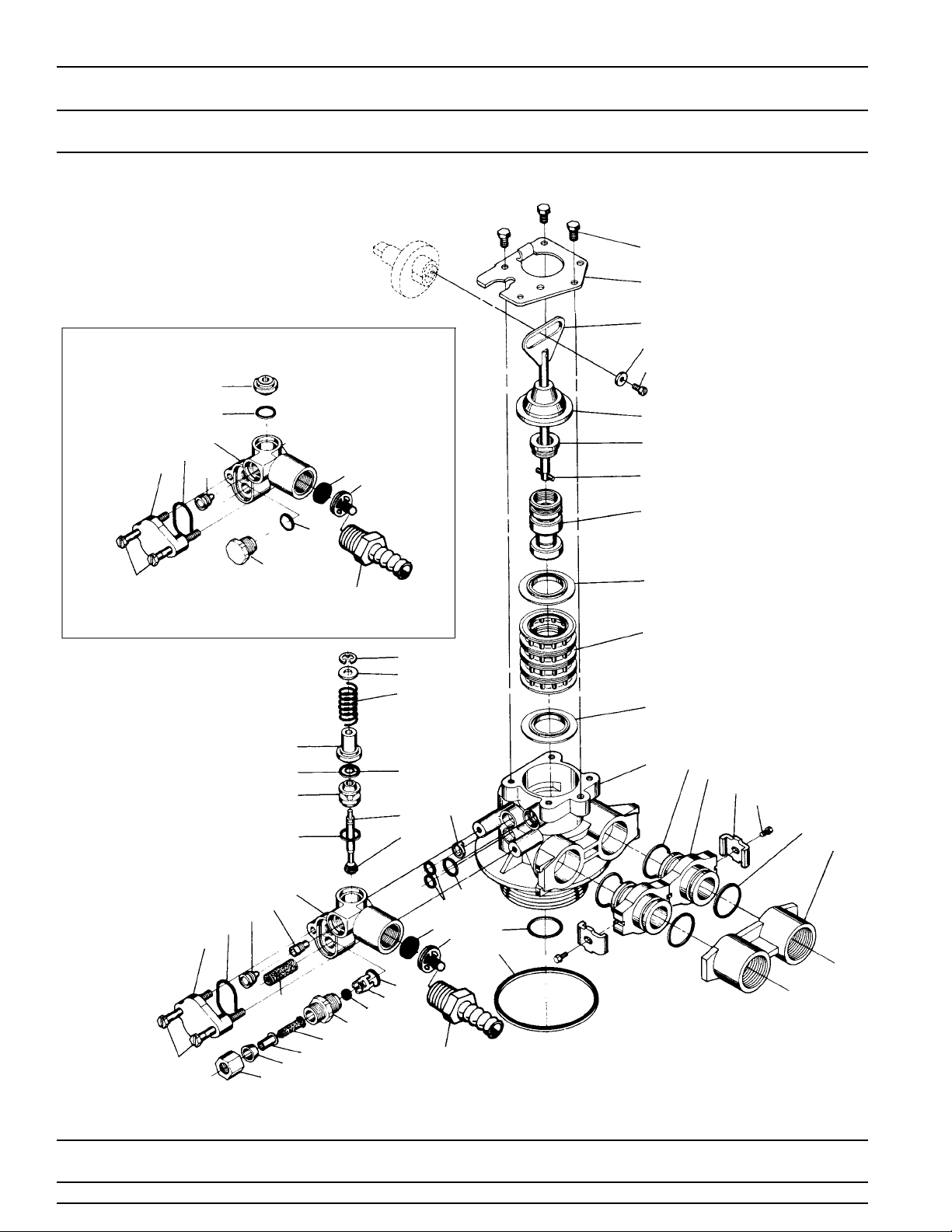
Control Valve Drive Assembly For (Clock Or Meter)
(See opposite page for parts list)
48
47
®
BACKWASH FILTER INJECTOR OPTION
55
20
22
21
26
23
39
53
14
29
20
30
20
42
52
43
34
33
32
31
27
28
46
10
49
50
12
9
8
7
11
2
2
3
16
15
1
17
16
51
Page 6
14
26
21
23
24
35
25
22
36
37
44
41
38
39
40
18
19
42
43
45
52
Printed in U.S.A.
4
5
45

MODEL 5600 & 5600 ECONOMINDER
Control Valve Drive Assembly For (Clock Or Meter)
Parts List
Item No. Quantity Part No. Description
1 . . . . . . . . . . . . . 2-4 . . . . . . . . . . . . .13255 . . . . . . . . . . . . . . . . . . . . . Adapter Clip (clock or meter)
2 . . . . . . . . . . . . . 5 . . . . . . . . . . . . . . .13242 . . . . . . . . . . . . . . . . . . . . . Seal
3 . . . . . . . . . . . . . 1 . . . . . . . . . . . . . . .61400-12 . . . . . . . . . . . . . . . . . . Valve Body Assembly - 1″ Dist.
4 . . . . . . . . . . . . . 1 . . . . . . . . . . . . . . .13304 . . . . . . . . . . . . . . . . . . . . . O-Ring - Distributor Tube - 1
5 . . . . . . . . . . . . . 1 . . . . . . . . . . . . . . .12281 . . . . . . . . . . . . . . . . . . . . . O -Ring - Top of Tank
6 . . . . . . . . . . . . . . . . . . . . . . . . . . . . . . . . . . . . . . . . . . . . . . . . . . . . . . . . Not Assigned
7 . . . . . . . . . . . . . 4 . . . . . . . . . . . . . . .14241 . . . . . . . . . . . . . . . . . . . . . Spacer
8 . . . . . . . . . . . . . 1 . . . . . . . . . . . . . . .13247 . . . . . . . . . . . . . . . . . . . . . Piston - Standard
9 . . . . . . . . . . . . . 1 . . . . . . . . . . . . . . .10696 . . . . . . . . . . . . . . . . . . . . . Piston Pin
10 . . . . . . . . . . . . . 1 . . . . . . . . . . . . . . .13001 . . . . . . . . . . . . . . . . . . . . . Piston Rod Assembly
11 . . . . . . . . . . . . . 1 . . . . . . . . . . . . . . .12953 . . . . . . . . . . . . . . . . . . . . .Piston Retainer
12 . . . . . . . . . . . . . 1 . . . . . . . . . . . . . . .13446 . . . . . . . . . . . . . . . . . . . . . End Plug As sembly Std . - White
14 . . . . . . . . . . . . . 2 . . . . . . . . . . . . . . .13315 . . . . . . . . . . . . . . . . . . . . .Screw - Injector Mounting
*15 . . . . . . . . . . . . . 2 . . . . . . . . . . . . . . .19228 . . . . . . . . . . . . . . . . . . . . . Adapter Coupling
*16 . . . . . . . . . . . . . 4 . . . . . . . . . . . . . . .13305 . . . . . . . . . . . . . . . . . . . . . O-Ring - Adapter Coupling
*17 . . . . . . . . . . . . . 2-4 . . . . . . . . . . . . .13314 . . . . . . . . . . . . . . . . . . . . . Screw - Adapter Coupling (clock or meter)
18 . . . . . . . . . . . . . 1 . . . . . . . . . . . . . . .12638 . . . . . . . . . . . . . . . . . . . . . O-Ring - Drain
19 . . . . . . . . . . . . . 2 . . . . . . . . . . . . . . .13301 . . . . . . . . . . . . . . . . . . . . . O-Ring - Injector
▲
20 . . . . . . . . . . . . . 2 . . . . . . . . . . . . . . .13302 . . . . . . . . . . . . . . . . . . . . . O-Ring - Brine Spacer
21 . . . . . . . . . . . . . 1 . . . . . . . . . . . . . . .13303 . . . . . . . . . . . . . . . . . . . . . O-Ring - Injector Cover
22 . . . . . . . . . . . . . 1 . . . . . . . . . . . . . . .13163 . . . . . . . . . . . . . . . . . . . . .Injector Body
▲
23 . . . . . . . . . . . . . 1 . . . . . . . . . . . . . . .10913U. . . . . . . . . . . . . . . . . . . . Injector Nozzle - Undrilled
24 . . . . . . . . . . . . . 1 . . . . . . . . . . . . . . .10914 . . . . . . . . . . . . . . . . . . . . .Injector Throat - Specify Size
25 . . . . . . . . . . . . . 1 . . . . . . . . . . . . . . .10227 . . . . . . . . . . . . . . . . . . . . .Injector Screen
26 . . . . . . . . . . . . . 1 . . . . . . . . . . . . . . .13166 . . . . . . . . . . . . . . . . . . . . . Injector Cover
27 . . . . . . . . . . . . . 1 . . . . . . . . . . . . . . .13172 . . . . . . . . . . . . . . . . . . . . . Brine Valve Stem
28 . . . . . . . . . . . . . 1 . . . . . . . . . . . . . . .12626 . . . . . . . . . . . . . . . . . . . . . Brine Valve Seat
29 . . . . . . . . . . . . . 1 . . . . . . . . . . . . . . .13165 . . . . . . . . . . . . . . . . . . . . .Brine Valve Cap
30 . . . . . . . . . . . . . 1 . . . . . . . . . . . . . . .13167 . . . . . . . . . . . . . . . . . . . . . Brine Valve Spacer
31 . . . . . . . . . . . . . 1 . . . . . . . . . . . . . . .12550 . . . . . . . . . . . . . . . . . . . . .Quad Ring
32 . . . . . . . . . . . . . 1 . . . . . . . . . . . . . . .11973 . . . . . . . . . . . . . . . . . . . . .Spring - Brine Valve
33 . . . . . . . . . . . . . 1 . . . . . . . . . . . . . . .16098 . . . . . . . . . . . . . . . . . . . . .Washer - Brine Valve
34 . . . . . . . . . . . . . 1 . . . . . . . . . . . . . . .11981-01 . . . . . . . . . . . . . . . . . .Retaining Ring
35 . . . . . . . . . . . . . 1 . . . . . . . . . . . . . . .10329 . . . . . . . . . . . . . . . . . . . . .B.L.F.C. Fitting Nut
36 . . . . . . . . . . . . . 1 . . . . . . . . . . . . . . .10330 . . . . . . . . . . . . . . . . . . . . . B.L.F.C. Ferrule
37 . . . . . . . . . . . . . 1 . . . . . . . . . . . . . . .10332 . . . . . . . . . . . . . . . . . . . . . B.L.F.C. Tube Insert
38 . . . . . . . . . . . . . 1 . . . . . . . . . . . . . . .12094 . . . . . . . . . . . . . . . . . . . . . B.L.F.C. Button - .25 GPM
▲
39 . . . . . . . . . . . . . 1 . . . . . . . . . . . . . . .12977 . . . . . . . . . . . . . . . . . . . . . O -Ring - B.L.F.C.
40 . . . . . . . . . . . . . 1 . . . . . . . . . . . . . . .13245 . . . . . . . . . . . . . . . . . . . . .B.L.F.C. Button Retainer
41 . . . . . . . . . . . . . 1 . . . . . . . . . . . . . . .13244 . . . . . . . . . . . . . . . . . . . . .B.L.F.C. Fitting, 3/8
42 . . . . . . . . . . . . . 1 . . . . . . . . . . . . . . . . . . . . . . . . . . . . . . . . . . . . . . . . . . D.L.F.C. Button - Specify Size
43 . . . . . . . . . . . . . 1 . . . . . . . . . . . . . . .13173 . . . . . . . . . . . . . . . . . . . . .D.L.F.C. Button Retainer
44 . . . . . . . . . . . . . 1 . . . . . . . . . . . . . . .12767 . . . . . . . . . . . . . . . . . . . . .Screen - Brine Line
45 . . . . . . . . . . . . . 1 . . . . . . . . . . . . . . .15348 . . . . . . . . . . . . . . . . . . . . . O -Ring - D.L.F.C. (not shown)
46 . . . . . . . . . . . . . 1 . . . . . . . . . . . . . . .13497 . . . . . . . . . . . . . . . . . . . . . Air Disperser
47 . . . . . . . . . . . . . 1 . . . . . . . . . . . . . . .13546 . . . . . . . . . . . . . . . . . . . . . End Plug Retainer
48 . . . . . . . . . . . . . 3 . . . . . . . . . . . . . . .12112 . . . . . . . . . . . . . . . . . . . . . Screw
49 . . . . . . . . . . . . . 1 . . . . . . . . . . . . . . .13363 . . . . . . . . . . . . . . . . . . . . . Washer
50 . . . . . . . . . . . . . 1 . . . . . . . . . . . . . . .13296 . . . . . . . . . . . . . . . . . . . . . Screw
51A. . . . . . . . . . . . 1 . . . . . . . . . . . . . . . 13398 . . . . . . . . . . . . . . . . . . . . . Yoke, Brass, 1″ NPT
51B. . . . . . . . . . . . 1 . . . . . . . . . . . . . . .18706. . . . . . . . . . . . . . . . . . . . . Yoke, Plastic, 1″ NPT
52 . . . . . . . . . . . . . 1 . . . . . . . . . . . . . . .13308 . . . . . . . . . . . . . . . . . . . . . Drain Hose Barb
▲
53 . . . . . . . . . . . . . 1 . . . . . . . . . . . . . . .13918 . . . . . . . . . . . . . . . . . . . . . B.L.F.C. - Plug
▲
55 . . . . . . . . . . . . . 1 . . . . . . . . . . . . . . .13857 . . . . . . . . . . . . . . . . . . . . . Brine Valve - Plug
* Not used with meter controls
▲
Note: Used in Backwash Filter
5 . . . . . . . . . . . . . . .17772 . . . . . . . . . . . . . . . . . . . . . Silicone Seal
1 . . . . . . . . . . . . . . .61400-11 . . . . . . . . . . . . . . . . . . Valve Body Assembly - 3/4″ Dist.
″
1 . . . . . . . . . . . . . . .10244 . . . . . . . . . . . . . . . . . . . . .O-Ring - Distributor Tube - 13/16
1 . . . . . . . . . . . . . . .13781 . . . . . . . . . . . . . . . . . . . . .Piston - Low Water
1 . . . . . . . . . . . . . . .13852 . . . . . . . . . . . . . . . . . . . . .Piston - Filter
1 . . . . . . . . . . . . . . .13446-10 . . . . . . . . . . . . . . . . . . End Plug Assembly Filter - Black
1 . . . . . . . . . . . . . . .13446-20 . . . . . . . . . . . . . . . . . . End Plug Assembly Low Water - Gray
1 . . . . . . . . . . . . . . .12095 . . . . . . . . . . . . . . . . . . . . . B.L.F.C. Button - .5 GPM
1 . . . . . . . . . . . . . . .12097 . . . . . . . . . . . . . . . . . . . . . B.L.F.C. Button - 1.0 GPM
″
1 . . . . . . . . . . . . . . .13708 . . . . . . . . . . . . . . . . . . . . . Yoke, Brass, 3/4″ NPT
1 . . . . . . . . . . . . . . .18706-02 . . . . . . . . . . . . . . . . . . Yoke, Plastic 3/4″ NPT
®
″
Printed in U.S.A.
Page 7
MODEL 5600 BACKWASH FILTER
Installation and Start-Up Procedure
MANUAL BACKWASH
KNOB
RED TIME
SET
BUTTON
TIME OF DAY
ARROW
1. The filter should be installed with the inlet, outlet, and
drain connections made in accordance with the
manufacturer’s recommendations and to meet
applicable plumbing codes.
BEFORE PLUGGING THE UNIT IN
2. Open a treated water tap down stream of the filter.
3. Manually index the filter to the service position and allow
the mineral tank to fill by slowly opening the main water
supply valve. ( any by pass should be in the service
position) NOTE: The water flowing from the down stream
tap will be cloudy and/or contain media fines as well as
air. Allow water to run until it appears clean and free of
air.
4. When a steady clean flow appears at the tap, close the
tap and the main water supply valve and allow the filter
media bed to settle 15 - 20 minutes.
5. Manually index the filter to the backwash position.
6. To prevent a sudden surge of water and air, partially
open the main water supply valve so that the flow at the
drain of the filter is approximately 1 gpm. The water at
the drain will again be cloudy and/or contain media fines
as well as air. Allow water to run until it appears clean
and free of air.
7. Continue to open the water supply valve until it is
completely open. Allow water to flow at the drain until all
media fines are washed out of the filter.
8. Manually index the filter to the service position, and
again open the down stream tap. Check to be sure that
the water flows clear. If necessary allow water to flow
until all media fines are gone. If the tap is equipped with
an aerator check that it is not plugged with media fines
and pipe scale.
9. Plug in the electrical cord and look in the sight hole on
the back of the timer motor to ensure that it is running.
24 HOUR GEAR
SKIPPER WHEEL
SHOWS EVERY
OTHER DAY
BACKWASH
RED POINTER
Set the days backwashing is to occur by sliding tabs on
the skipper wheel outward to expose trip fingers. Each
tab is one day. Finger at red pointer is tonight. Moving
clockwise from red pointer, extend or retract fingers to
obtain the desired backwash schedule.
10. Set time of day by depressing red button and spin the 24
hr gear until the present time of day is visible above the
time of day arrow.
A. CYCLE TIMES & FLOW DIAGRAMS
pages 16-19
(with all following positions, disregard the brine tank, air
check and all other items associated with brining)
1. Service Position - same as pictured.
2. Preliminary Rinse Position
- same as pictured with standard piston (white end
plug) or filter piston (black end plug).
- eliminated with low water piston (gray end plug).
3. Backwash Position
- same as pictured with standard piston.
- 15 minutes with filter piston.
- 7 minutes with low water piston.
4 & 5. Brine & Slow Rinse Positions
- eliminated, resulting in a 50 minute pause, no water
flows during this time.
6. Rapid Rinse
- same as pictured with standard piston.
- 15 minutes with filter piston.
- 7 minutes with low water piston.
7. Settling Rinse
- same as pictured with standard or filter piston.
- eliminate with low water piston.
8. Brine Tank Refill Position
- eliminated, filter is back in service at this time.
Page 8
Printed in U.S.A.
MODEL 5600 ECONOMIDER
®
Installation and Start-up Procedure (Cont’d.)
The water softener should be installed with the inlet, outlet and drain connections made in accordance with
manufacturer’ s recommendations and to meet applicable plumbing codes.
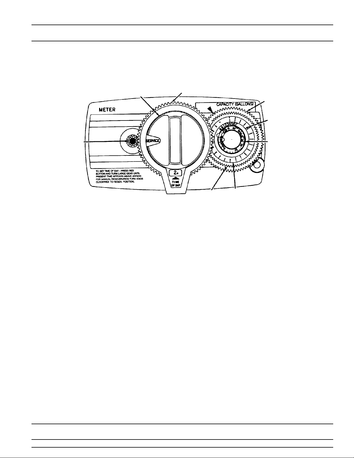
MANUAL
REGENERATION
KNOB
24 HOUR GEAR
PROGRAM WHEEL
PEOPLE DIAL
RED TIME
SET
BUTTON
1. Manually index the softener control into the service
position and let water flow into the resin tank. When
the water flow stops, open a softened water tap until
all air is released from the lines, then close the tap.
NOTE: The various regeneration positions may be
dialed manually by turning the knob on the front of
the control until the indicator shows that the softener
is in the desired position.
2. Set water usage program wheel using any one of the
following procedures:
Typical Residential Application
To program, just set the time, set the hardness and it
automatically monitors system needs and
regenerates only when necessary. To set time of day
press red time set button and turn 24 hour gear until
present time of day is at “time of day”. Set program
wheel by lifting the “people” dial and rotating it so that
the number of people in the household is aligned with
the household grains per gallon water hardness.
Release the dial and check for firm engagement at
setting. (This method will provide reserve capacity
based on 75 gallons per person.)
Optional Programming Procedures
Calculate the gallon capacity of the system, subtract
the necessary reserve requirement and set the
gallons available at the small white dot on program
wheel gear. Note, drawing shows 850 gallon setting.
GRAINS PER GALLON
WATER HARDNESS
SCALE
WHITE
DOT LABEL
The capacity (gallons) arrow denotes remaining
gallons exclusive of fixed reserve.
3. Rotate the program wheel counterclockwise until it
stops at regeneration position.
4. Manually index the control to the back-wash position
and allow water to flow at the drain for 3 or 4 minutes.
5. Remove back cover plate.
6. Make sure than the salt dosage is set as
recommended by the manufacturer. Manually index
the control to the brine fill position and allow the brine
tank to fill to the top of the air check.
7. Manualy index the control to the brine rinse position
and allow the control to draw water from the brine
tank until it stops.
8. Plug in the electrical cord and look in the sight hole in
the back of the montor to see that it is running.
9. Manually advance the control to the beginning of the
brine fill position and allow the control to return to the
service position automatically.
10. Fill the brine tank with salt.
11. Replace back cover on the control. Be sure cable is
not pinched between cover and housing.
12. Make sure that any by-pass valving is left in the
normal service position.
GALLONS
Printed in U.S.A.
Page 9
 Loading...