

Fleck 9100TS Upflow Service Manual

FLECK 9100TS UPFLOW
SERVICE MANUAL
waterpurification.pentair.com
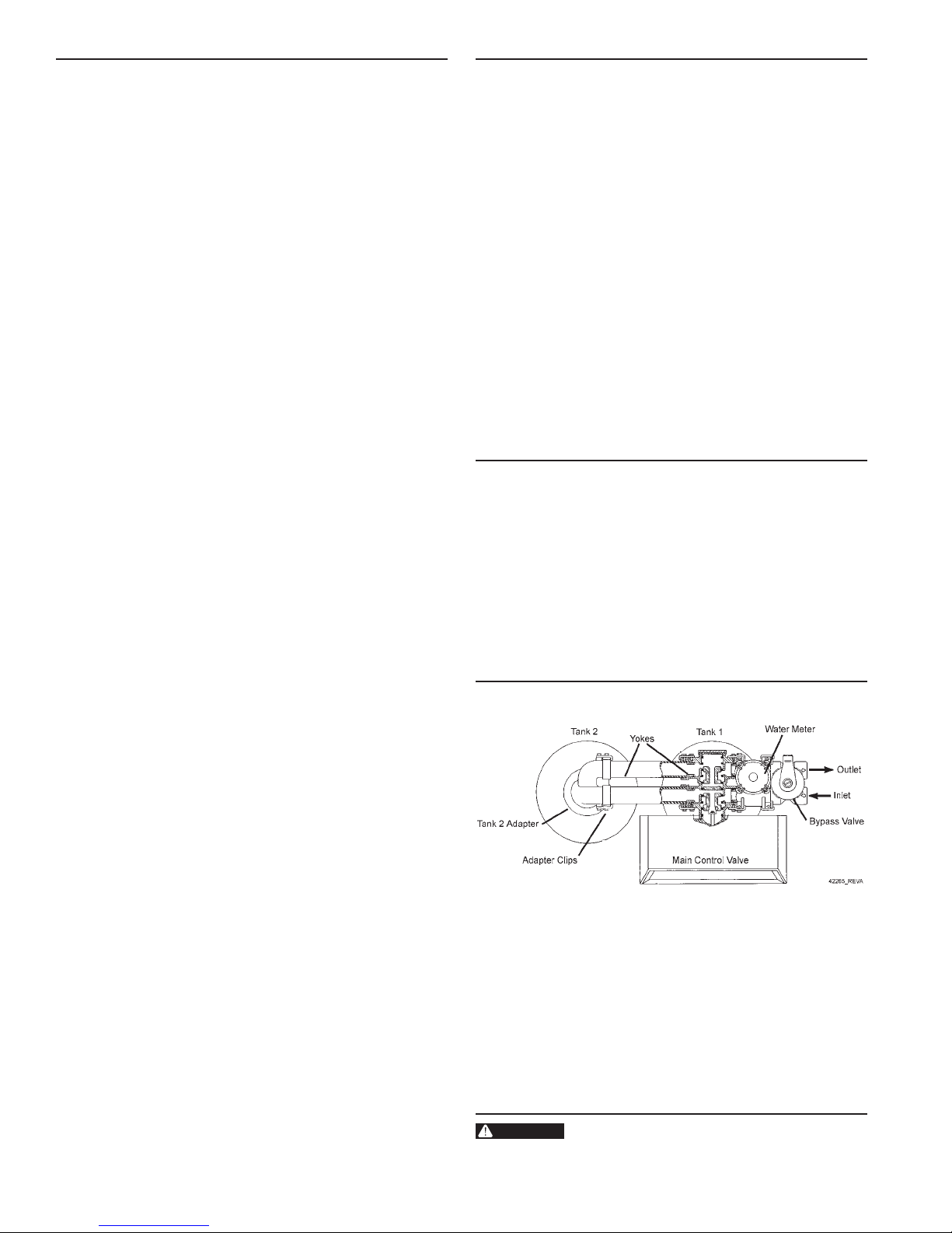
TABLE OF CONTENTS
WARNING:
JOB SPECIFICATION SHEET .................................................... 2
HOW TO USE THIS MANUAL .................................................... 2
EQUIPMENT CONFIGURATION ................................................ 2
SAFETY INFORMATION ............................................................ 3
INSTALLATION INSTRUCTIONS ............................................... 3
CONTROLLER FEATURES ........................................................ 6
INITIAL STARTUP INSTRUCTIONS .......................................... 7
USER PROGRAMMING ............................................................. 8
PROGRAMMING MODE ............................................................ 11
AUTOMATIC CLEANING CYCLE ............................................... 15
DISINFECTION OF WATER CONDITIONING SYSTEMS ............ 15
WIRING DIAGRAMS .................................................................. 16
POWERHEAD ASSEMBLY......................................................... 17
9100 CONTROL VALVE ASSEMBLY .......................................... 18
9100 SECOND TANK ASSEMBLY ............................................. 19
TURBINE METER ASSEMBLY - P/N 60626 ............................. 20
PADDLE METER ASSEMBLY -P/N 60086-50 ........................... 20
1" METER ASSEMBLY - P/N 60622 .......................................... 21
BYPASS VALVE ASSEMBLY (METAL) ........................................ 22
BYPASS VALVE ASSEMBLY (PLASTIC) ..................................... 22
SAFETY BRINE VALVE .............................................................. 23
PROBE KIT ............................................................................... 24
TROUBLESHOOTING ................................................................ 25
9000/9100 METER FLOW DATA ................................................ 26
9000/9100 INJECTOR FLOW DATA (
1600 SERIES INJECTORS) ....................................................... 27
9100 CONTROL DIMENSIONS.................................................. 28
WATER CONDITIONER FLOW DIAGRAMS ............................... 29
SERVICE ASSEMBLIES ............................................................ 31
JOB SPECIFICATION SHEET
Job No: _____________________________________________
Model No: ___________________________________________
Water Test: __________________________________________
Capacity Per Unit: _____________________________________
Mineral Tank
Size: ____________ Diameter: ___________Height: _________
Brine Tank Size and Salt Setting per Regeneration: _________
9100TS Control Valve Specifications:
1. Regeneration Program Setting:
a. Brine and Slow Rinse: ______________________ Minutes
b. Backwash: _______________________________ Minutes
c. Rapid Rinse: _____________________________ Minutes
d. Brine Tank Refill: _________________________ Minutes
2. Drain Line Flow Control: _________________________ gpm
3. Brine Refill Rate: _______________________________ gpm
4. Injector Size: ______________________________________
HOW TO USE THIS MANUAL
This installation manual is designed to guide the installer
through the process of installing and starting water
conditioning systems featuring the 9100TS controller.
This manual is a reference and will not include every system
installation situation. The person installing this equipment
should have:
• Training in the 9100TS control and the 9000/9100 valve.
• Knowledge of water conditioning and how to determine
proper control settings.
• Adequate plumbing skills.
EQUIPMENT CONFIGURATION
9100TS Configuration
Figure 1
CALIFORNIA PROPOSITION 65 WARNING
This product contains chemicals known to the
State of California to cause cancer or birth
defects or other reproductive harm.

SAFETY INFORMATION
General Warnings And Safety Information
Electrical
• There are no user-serviceable parts in the AC adapter,
motor, or controller. In the event of a failure, these items
should be completely replaced.
• All electrical connections must be completed according to
local codes.
• Use only the power transformer supplied with this water
conditioning system.
• The power outlet must be grounded and always on.
• To disconnect power, unplug the AC adapter from its
power source.
Mechanical
• Do not use petroleum based lubricants such as Vaseline,
oils, or hydrocarbon based lubricants. Use only 100%
silicone lubricants.
• All plastic connections should be hand tightened. PTFE
tape may be used on connections that do not use an
O-ring seal. Do not use pliers or pipe wrenches.
• All plumbing must be completed according to local codes.
• Use only lead-free solder and flux, as required by
federal and state codes, when installing soldered copper
plumbing.
• The drain line must be a minimum of 1/2-inch diameter.
Use 3/4-inch pipe if the pipe length is greater than 20 feet
(6 m).
• Do not support the weight of the system on the control
valve fittings, plumbing, or the bypass.
General
• Observe all warnings that appear in this manual.
• This system is not intended to be used for treating water
that is microbiologically unsafe or of unknown quality
without adequate disinfection before or after the system.
• Keep the unit in the upright position. Do not turn on side,
upside down, or drop. Turning the tank upside down will
cause media to enter the valve.
• Operating water temperature is between 35°F (1°F) and
100°F (38°C).
• Operating water pressure range : 20 to 125 psi (1.38 to
8.27 bar).
• Use only salts designed for water softening. Acceptable
salt type is sodium chloride pellet salt.
• Follow state and local codes for water testing.
• When filling media tank, do not open water valve
completely. Fill tank slowly to prevent media from exiting
the tank.
• Always make modifications to house plumbing first.
Connect to valve last.
• Plastic parts and O-rings may be damaged by heat and
solvents. When constructing plumbing connections allow
heated parts to cool and protect parts from solvents.
Location Selection
Location of a water treatment system is important. The
following conditions are required:
• Level platform or floor.
• Ambient temperatures over 35°F (1°C) and below 120°F
(49°C).
• Constant electrical supply to operate the controller.
• Total minimum pipe run to water heater of ten feet (three
meters) to prevent backup of hot water into system.
• Local drain or tub for discharge as close as possible.
• Water line connections with shutoff or bypass valves.
• Must meet any local and state codes for site of
installation.
• Valve is designed for minor plumbing misalignments. Do
not support weight of system on the plumbing.
• Room to access equipment for maintenance and adding
salt.
INSTALLATION INSTRUCTIONS
Things You Need to Know
• When the controller is first plugged in, it may display a
flashing hourglass and the message Err 3, this means
that the controller is rotating to the home position.
Grounding the Plumbing
It is important that the plumbing system be electrically
grounded. When a water softener is installed, a non-metallic
bypass valve may interrupt the grounding. To maintain
continuity, a grounding strap can be purchased at a hardware
store (Figure 2). When it is installed the strap will connect the
plumbing into the softener to the plumbing out of the softener.
If you have other water treating equipment such as a
chlorinator, sediment filter, neutralizer, iron filter, or taste
and odor filter they should be installed upstream of the water
softener.
Figure 2
FLECK 9100TS Upflow • 3
B
INSTALLATION INSTRUCTIONS continued
WARNING:
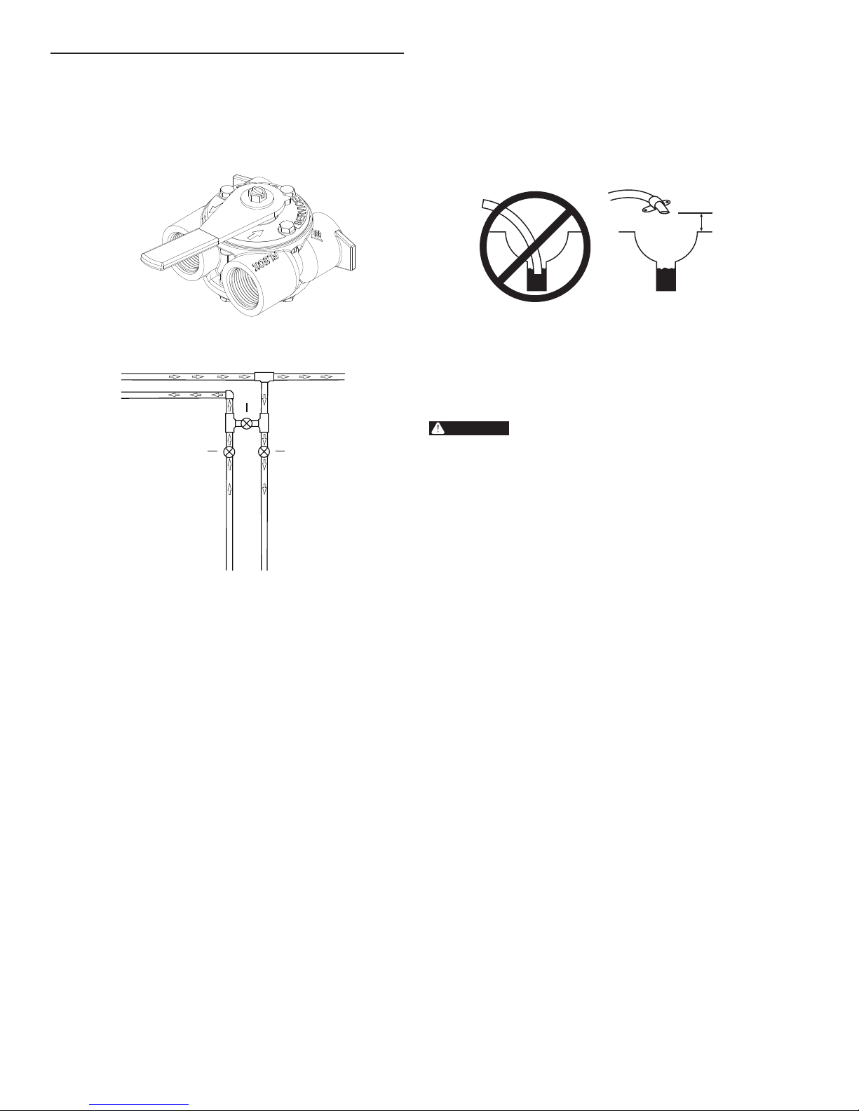
Bypass Valve
A bypass valve system should be installed on all water
conditioning systems. Bypass valves isolate the conditioner
from the water system and allow unconditioned water to be
used. Service or routine maintenance procedures may also
require that the system is bypassed. Figures 3 and 4 show the
two common bypass methods.
Figure 3 Bypass Valve
2
1
3
3. Where the drain line is elevated but empties into a drain
below the level of the control valve, form a 7-inch (18-cm)
loop at the far end of the line so that the bottom of the loop
is level with the drain line connection. This will provide
an adequate siphon trap. Where the drain empties into an
overhead sewer line, a sink-type trap must be used.
Secure the end of the drain line to prevent it from moving.
INCORRECT
Construct air gap as shown or purchase air
gap device as used with clothes washers.
CORRECT
1" AIR GAP
Figure 5 Drain Line Connection
NOTE: Waste connections or drain outlets should be designed
and constructed to provide for connection to the
sanitary waste system through an air gap of two pipe
diameters or one inch (22 mm) whichever is larger.
Never insert drain line directly into a drain,
sewer line, or trap (Figure 5 Drain Line
Connection). Always allow an air gap between
the drain line and the wastewater to prevent
the possibility of sewage being back-siphoned
into the softener.
Figure 4 Manual Bypass
If this unit includes a bypass valve (Figure 3), it can be used by
itself or with a manual bypass (Figure 4).
Manual Bypass In Service Position
• Valves 1 and 3 open
• Valve 2 closed
Bypassed Position
• Valve 2 open
• Valves 1 and 3 closed
Drain Line Connection
NOTE: Standard commercial practices are expressed here.
1. The unit should be above and not more than 20 feet
2. The drain line may be elevated up to 6 feet (1.8 m) providing
Local codes may require changes to the following
suggestions. Check with local authorities before
installing a system.
(6.1 m) from the drain. Use an appropriate adapter fitting
to connect plastic tubing to the drain line connection of the
control valve.
the run does not exceed 15 feet (4.6 m) and water pressure
at the softener is not less than 40 psi (2.76 bar). Elevation
can increase by 2 feet (61 cm) for each additional 10 psi (.69
bar) of water pressure at the drain connector.
General Installation Notes
1. Place the softener tanks where you want to install the unit.
NOTE: Be sure the tanks are level and on a firm base.
2. During cold weather it is recommended that the installer
warm the valve to room temperature before operating.
3. Perform all plumbing according to local plumbing codes.
— Use a 1/2" minimum pipe size for the drain.
4. Lubricate the distributor O-ring seal and tank O-ring seal.
Place the main control valve on one tank and the tank
adapter on the second tank.
NOTE: If required, solder copper tubing for tank
interconnection before assembling on the main
control valve and tank adapter. Maintain a
minimum of 1" distance between tanks on final
assembly.
5. Solder joints near the drain must be done before connecting
the Drain Line Flow Control fitting (DLFC).Leave at least
6" (152 mm) between the DLFC and solder joints when
soldering pipes that are connected on the DLFC. Failure to
do this could cause interior damage to DLFC.
6. Use only plumber tape on the drain fitting.
7. Be sure the floor under the salt storage tank is clean and
level.
8. Place approximately 1" (25 mm) of water above the grid
plate of the salt storage tank before filling with salt. Add
salt to brine tank so that salt level is above the brine well
air check.
9. Make all electrical connections according to codes. Plug the
valve into an approved power source.
10. Tank one has control valve and tank two has adapter.
11. Look on the right side of the control valve, it has indicators
showing which position the control valve is in during
Regeneration and which tank is In Service.
FLECK 9100TS Upflow
4 •
INSTALLATION INSTRUCTIONS continued
WARNING:
Brine Line Connection
The brine line from the brine tube connects to the valve. Make
certain the connections are hand tightened. Be sure that the
salt line is secure and free from air leaks. Even a small leak
may cause the salt line to drain out, and the softener will not
draw salt from the tank. This may also introduce air into the
valve causing problems with valve operation.
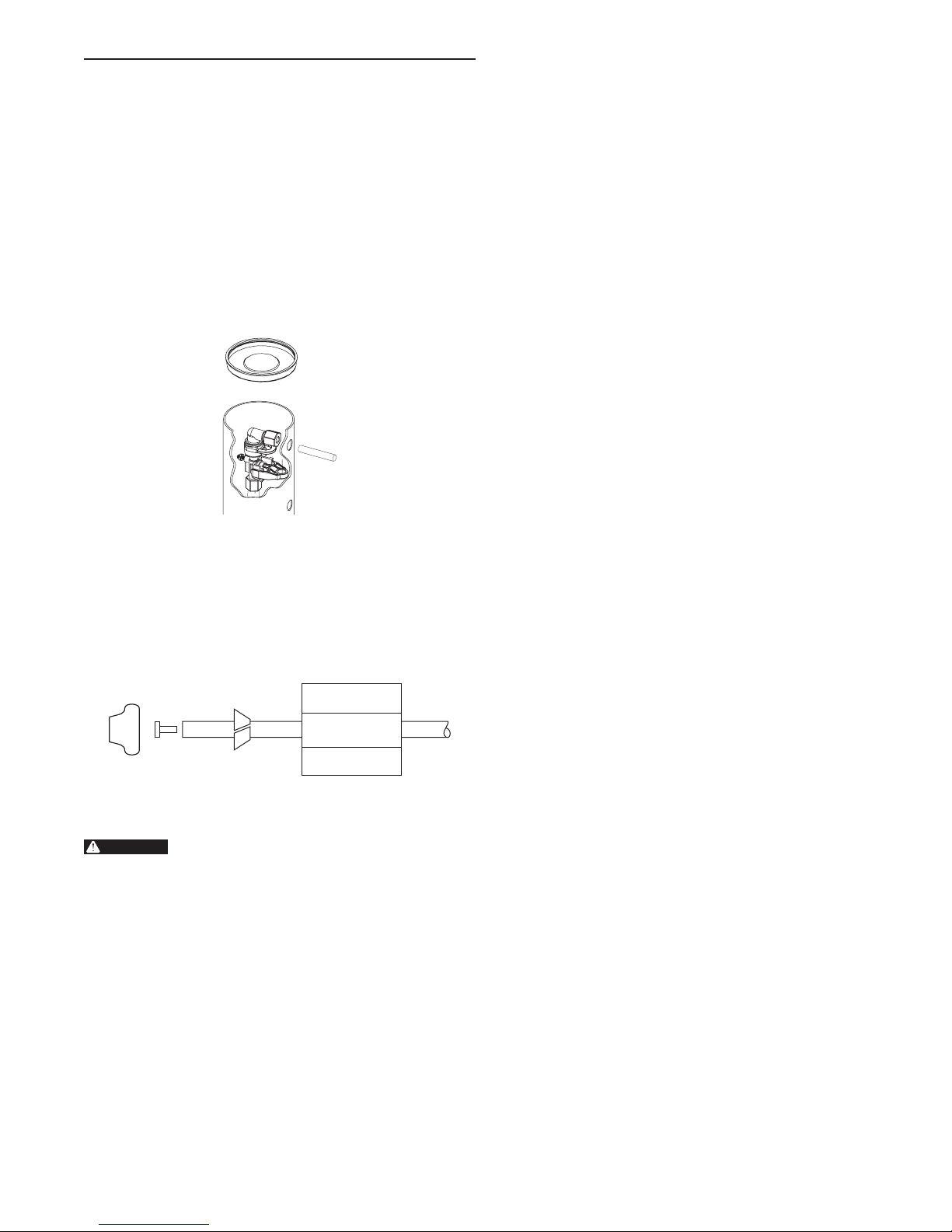
To install the brine line:
1. Inside the salt tank, remove the cap from the large cylinder
to gain access to the connection.
2. Be sure the brass insert is in the end of the brine tubing.
Insert the tubing through the opening in the tank.
3. Push the tubing into the plastic nut. Slowly unscrew the nut
until the tubing moves into the connection. The tubing will
hit bottom.
9100TS Control Operation
Power Loss Memory Retention
The 9100TS control features battery-free Time of Day and Day
of Week retention during temporary loss of power. A super
capacitor is designed to keep time for 8 to 24 hours depending
on the installation. If the super capacitor is exhausted the
9100TS control will display four dashes (- - : - - ) immediately
upon power up. The Time of Day and Day of Week must be
reset.
All other programmed parameters are stored in the static
memory and are retained.
Figure 6
NOTE: Once the tubing has been pushed into the nut it cannot
4. Hand tighten the nut until the connection is tight.
5. Make compression fitting connection between brine line
be pulled out. The nut will need to be removed. See
Figure 6 for correct assembly.
and valve (Figure 7).
Figure 7
Electrical Connection
This valve and control are for dry location use
only unless used with a Listed Class 2 power
supply suitable for outdoor use.
The controller operates on 24-volt alternating current power
supply. This requires use of the supplied AC adapter included
with your system.
AC Adapter
Make sure power source matches the rating printed on the AC
adapter.
NOTE: The power source should be constant. Be certain
the AC adapter is not on a switched outlet. Power
interruptions longer than 8 hours may cause the
controller to lose the time setting. When power is
restored, the time setting must then be re-entered.
FLECK 9100TS Upflow • 5
CONTROLLER FEATURES
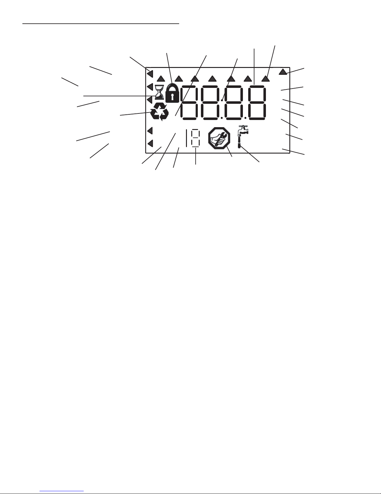
Display Icons & Cursors
14
13
Regeneration Time
15
Salt Amount
12
16
Time/Day
11
9
10
7
2
8
SU MO TU WE TH FR SA DAYS
PM
MIN
g/L
KGx2
1
3
4
5
Capacity
26
25
NOTE: In normal operation and during programming, only a
1. This cursor is displayed when the days between
2. One of these cursors is displayed to indicate which day will
3. "PM" indicates that the time displayed is between 12:00
4. When "MIN" is displayed, the value entered is in minute
5. When g/L is displayed, the value for regenerant amount
6. When "Kg" is displayed, the value entered is in kilograms or
7. Four digits used to display the time or program value. Also
8. Colon used as part of the time display.
9. Locked/unlocked indicator. In Level I Programming this
10. When "x2" is displayed, a second regeneration has been
11. The recycle sign is displayed (flashing) when a regeneration
12. The display cursor is next to "SALT AMOUNT" when
13. The display cursor is next to "REGENERATION TIME" when
14. The display cursor is next to "TIME/DAY" when
15. The hourglass is displayed when the motor is running. The
16. These cursors appear next to the item that is currently
6 •
few of the icons are actually displayed.
regeneration are being programmed (used with .5 to 30 day
regeneration programming).
be programmed into the controller.
noon and 12:00 midnight (there is no AM indicator). PM
indicator is not used if clock mode is set to 24-hour.
increments.
entered is in grams/Liter of resin.
kilograins.
used for error codes.
is displayed when the current parameter is locked-out.
It is also used in Level II Programming to indicate if
the displayed parameter is locked (icon flashes) when
controller is in Level I.
called for.
at the next time of regeneration has been called for. Also
displayed (continuous) when in regeneration.
programming the amount of regenerant.
programming the time of regeneration and the days of
regeneration.
programming the current time and day.
piston should be moving.
displayed.
FLECK 9100TS Upflow
Hardness
24
C
23
H
22
6
x100P
Lbs/ft
3
17
18
20
21
17. X100 multiplier for large values.
3
18. When Lbs/ft
entered is in pounds/cubic foot of resin.
19. Faucet is displayed when the current flow rate is displayed.
Control may show the faucet and "0", indicating no flow.
20. Maintenance interval display turns on if the months in
service exceed the value programmed in P11.
21. Displays the tank in service during normal operating mode.
Used with #22, #23 and #24 in programming mode or
regeneration.
22. History Values (H). The number displayed by #21 identifies
which history value is currently displayed.
23. Parameter (P). Displayed only in Level II Programming.
The number displayed by #21 identifies which parameter is
currently displayed.
24. Cycle (C). The number displayed by #21 is the current cycle
in the regeneration sequence.
25. Hardness setting.
26. Capacity display—shows estimated system capacity.
is displayed the value for regenerant amount
19

CONTROLLER FEATURES continued INITIAL STARTUP INSTRUCTIONS
Keypad - Buttons
1 2 3 4
Figure 8
1. SET. Used to accept a setting that normally becomes stored
in memory. Also used together with the arrow buttons.
2. DOWN arrow. Generally used to scroll down or decrement
through a group of choices.
3. UP arrow. Generally used to scroll up or increment through
a group of choices.
4. REGENERATE. Used to command the controller to
regenerate. Also used to change the lock mode.
NOTE: If a button is not pushed for thirty seconds, the
controller returns to normal operation mode.
Pushing the Regenerate button immediately returns
the controller to normal operation except when
the controller is in regeneration mode or Level II
Programming mode.
After you have performed the installation steps, the conditioner
will need to be placed into operation for the first time.
NOTE: The controller will be shipped in the service (treated
water) position. Do not move the piston before
performing the following steps.
The incoming supply water should be turned off.
Power-up The Control
1. Plug the transformer into a non-switched outlet. The
display will show 9100. If this is the first time the control is
powered up the display will show "_.__".
NOTE: err3 will be displayed if the control does not detect
the valve at the home position and that the motor
is turned on. As soon as it detects the valve at the
home position, the motor will be turned off and error
will disappear. The piston will move to service if not
already in service. These movements may take up to
five minutes.
Program the Controller
2. Program the Controller for initial operation using the User
Programming Guide (See Quick Start on page 8 or Step-byStep Instructions on pages 9-10).
Remove Air From Tank 1
3. Press and hold the REGEN button for three seconds. The
controller will enter regeneration mode.
4. Press both SET and UP buttons to advance to backwash
(Cycle 2).
5. Open the incoming water supply valve slowly to the quarter
open position.
6. Allow water to run down the drain until air exits the tank.
When water flows steady from the drain, open inlet valve
fully. Allow to run until water is clear in drain.
7. Hold SET and UP buttons for three seconds to cancel
regeneration.
Remove Air From Tank 2
8. Close inlet water supply valve.
9. Press and hold the REGEN button for three seconds. The
controller will enter regeneration mode.
10. Press both SET and UP buttons to advance to backwash
(Cycle 2).
11. Repeat steps 5 and 6 above.
12. Allow the controller to finish regeneration on its own. This
will fill the brine tank.
FLECK 9100TS Upflow • 7
Regeneration Time
Screen Buttons to Description Range
Control programming is complete
Regeneration Time
Regeneration Time
Regeneration Time
Regeneration Time
Regeneration Time
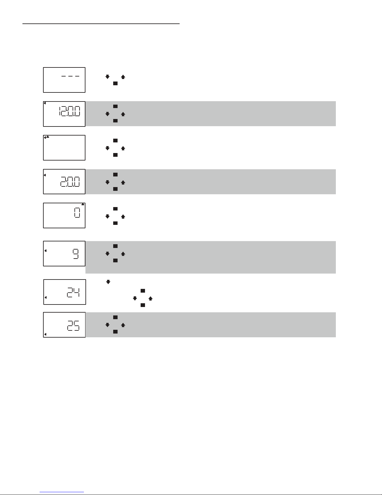
USER PROGRAMMING
Level I Programming - 9100TS
Press
SU MO TU WE TH FR SA DAYS
Time/Day
PM
Lbs/ft
KG
then
press
press
then
press
press
then
press
press
then
press
press
then
press
press
then
3
press
press
to override
press
then
press
or
or
or
or
or
or
press
then
or
press
or
Salt Amount
Capacity
Hardness
SU MO TU WE TH FR SA DAYS
Time/Day
Salt Amount
Capacity
Hardness
SU MO TU WE TH FR SA DAYS
Time/Day
Salt Amount
Capacity
Hardness
SU MO TU WE TH FR SA DAYS
Time/Day
Salt Amount
Capacity
Hardness
SU MO TU WE TH FR SA DAYS
Time/Day
Salt Amount
Capacity
Hardness
SU MO TU WE TH FR SA DAYS
Time/Day
Salt Amount
Capacity
Hardness
SU MO TU WE TH FR SA DAYS
Time/Day
Regeneration Time
Salt Amount
Capacity
Hardness
SU MO TU WE TH FR SA DAYS
Time/Day
Regeneration Time
Salt Amount
Capacity
Hardness
P0 Resin Volume
Select correct resin volume.
Default is 1 cubic foot/30 liters.
P1 Time of Day (12 hr)
Set to me of day.
Note: Seng includes PM indicator.
P2 Day of Week
Set to actual day of the week.
P3 Time of Regeneraon
Set to desired me of regeneraon.
P4 Days Override
Leave at 0 to disable
or
Set to desired days between
regeneraon.
Default is 0 days.
P6 Salt Dosage
Set to desired dosage
lbs per cubic feet of resin
Default is 9 lbs/ / 110 gm/l.
3
P7 Capacity
Capacity calculated by control
Use to OVERRIDE calculated capacity.
P8 Hardness
Set to actual water hardness
in grains per gallon / ppm.
Cubic Feet:
0.75 to 2.00
Liters:
20 to 60
Days: 0 (Disable)
0.5 to 30
3
Lbs/ :
3 to 15
gm/l:
50 to 200
NOTE: The regen icon may begin flashing after the control
displays err3 or after the time is reset following a
power outage. This indicates that a regeneration will
occur at the next scheduled regeneration based on
metered water usage during the error condition or
power outage.
8 • FLECK 9100TS Upflow
USER PROGRAMMING continued
Regen
Time & Da
SU MO TU WE TH FR SA DAYS
Regen
FR
Regen
SU MO TU WE TH FR SA DAYS
Regen
SU MO TU WE TH FR SA DAYS
Figure 11
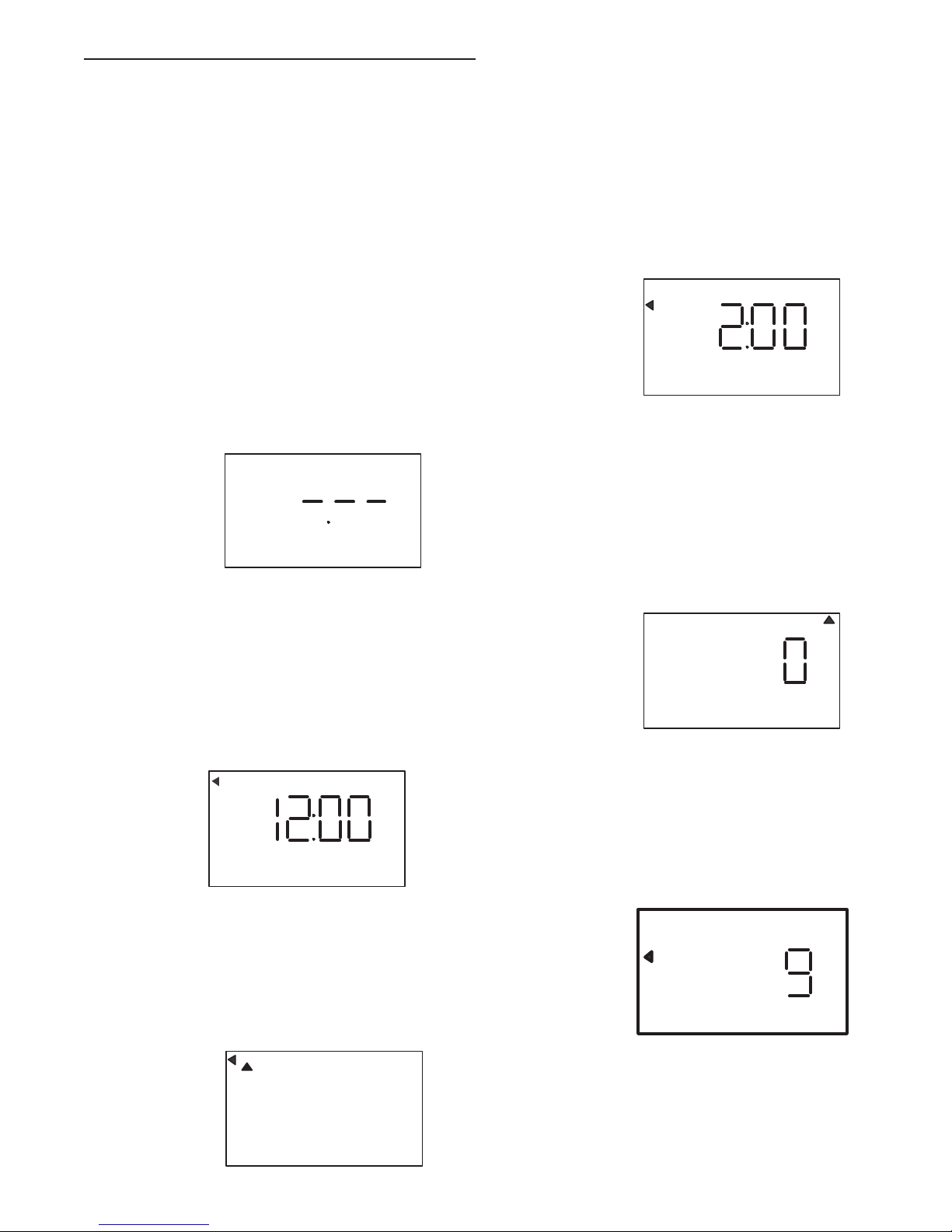
Step-by-Step Instructions
Step 1: Program System Size
This step may have been performed by your system’s OEM
manufacturer. In this case, proceed to step 2.
NOTE: Capacity is the result of the amount of media in the
tank and the salt setting. The default capacity will be
changed by selecting a different regenerant setting.
• Input system size – media volume – in cubic feet (liters).
• Use UP and DOWN buttons to scroll through resin volume
choices.
• Choose the nearest volume to your actual system size.
• Press SET to accept the system size you’ve selected.
NOTE: If the controller was incorrectly set to the wrong
size, press the DOWN button and SET button for five
seconds to display resin volume in "HO". Press and
hold the SET button for five seconds to reset the
controller. Use the UP or DOWN buttons to increment
the display to the correct resin volume. Press SET.
SU MO TU WE TH FR SA DAYS
Time & Day
Time & Day
Salt
Capacity
Hardness
Figure 9
Step 4: Set Regen Time
• 2:00 (AM) is the default time of regeneration. To accept
this time, press the DOWN button to move to step 5.
• To change the regen time, press SET – causing “2:00” to
flash.
• Use the UP and DOWN buttons to advance to the desired
regen time.
• Press SET to accept the time and advance to the next
parameter.
Time & Day
Time & Day
Salt
Capacity
Hardness
Figure 12
Step 5: Set Calendar Override
• Set number of days for calendar override.
• “0” days (disabled) is the default for calendar override.
• Days can be adjusted from ½ (.5) to 30 days.
• To change, press SET to make the “0” flash.
• Use the UP and DOWN buttons to change to the number
of days desired. Press SET to accept the regen frequency,
and advance to the next cycle.
Step 2: Program Time of Day
• While “12:00” is blinking, set the correct time of day.
• Use the UP and DOWN buttons to scroll to the correct
time of day.
• “PM” is indicated, “AM” is not indicated.
• Press SET to accept the correct time of day and advance
to the next parameter.
y
Capacity
Hardness
Figure 10
Step 3: Set Day of Week
• Press SET to make the arrow under “SU” flash.
• Use the UP and DOWN buttons to advance the arrow until
it is under the correct day of week.
• Press SET to accept and advance to the next parameter.
SU MO TU WE TH
Time & Day
Time & Day
Capacity
Hardness
Salt
SA DAYS
Time & Day
Time & Day
Salt
Capacity
Hardness
Figure 13
Step 6: Amount of Regenerant used per Regeneration
• Set desired regenerant amount.
• Default setting is 9 lbs/cubic feet (120 gm/l).
• To change salt setting, press the SET button and use the
UP and DOWN buttons to change to the desired setting.
• Press SET to accept the setting and advance to the next
parameter.
SU MO TU WE TH FR SA DAYS
Time/Day
Regeneration Time
Salt Amount
Capacity
Hardness
Lbs/ft
3
Figure 14
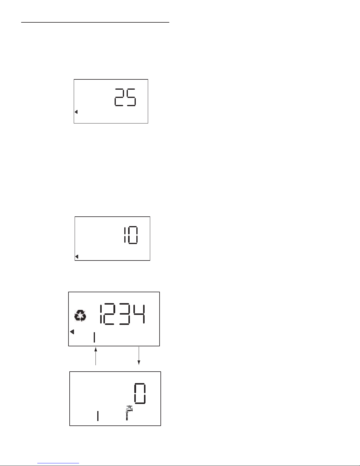
Step 7: Estimated Capacity
• System capacity is displayed in total kilograins or
kilograms of hardness removed before a regeneration is
necessary.
FLECK 9100TS Upflow • 9
Regen
SU MO TU WE TH FR SA DAYS
Regen
SU MO TU WE TH FR SA DAYS
USER PROGRAMMING continued
• Value is derived from the system’s resin volume input and
salt amount input.
• To override capacity on the control, press SET to make the
default capacity flash. Use the UP and DOWN buttons to
increment to the desired capacity.
• Press SET to accept the setting and advance to the next
parameter.
Time & Day
Time & Day
Salt
KG
Capacity
Hardness
Figure 15
Step 8: Enter Hardness
• Enter inlet water hardness at installation site.
• Default hardness setting is 10 grains (170 ppm).
• To change hardness, press SET to make the setting flash.
Use the UP and DOWN buttons to scroll to the desired
hardness.
• Press SET to accept the entered hardness value.
• The control will return you to the normal operation mode.
Initial programming is now complete. The control will return
to normal operation mode if a button is not pushed for 30
seconds.
Time & Day
Time & Day
Backwash Time
Figure 17
The display shows the number of the tank in service (small
digit next to CPH position). The display also alternates between
Capacity Remaining and Flow Rate (faucet icon) for the tank in
service.
NOTE: The Regen icon is steady on when in regeneration.
NOTE: The faucet icon is displayed when there is flow. The
display will show the faucet icon when the flow rate is
displayed, even if the flow rate is zero. The faucet icon
will turn off when the capacity is displayed.
Capacity
Hardness
In Service Display
Time & Day
Regen Time & Day
Salt Amount
Capacity
Hardness
Time & Day
Regen Time & Day
Salt Amount
Capacity
Hardness
Figure 16
SU MO TU WE TH FR SA DAYS
SU MO TU WE TH FR SA DAYS
10 • FLECK 9100TS Upflow
 Loading...