

Fleck 7000 SXT Installation Manual

Page 1 of 17
Copyright © 2012 Quality Water Treatment, All right reserved. rev. 4.19.2013 http:// www.Qualitywatertreatment.com
Fleck 7000 SXT
Fleck 7000 SXT
Installation Guide
Before you assemble your new system, be sure that the following conditions
have been met for placement of your softener:
Level, firm surface, such as concrete, on which to place the softener
tank and salt tank AKA Brine Tank.
Nearby floor drain or standpipe to connect to the softener for use
during each regeneration.
Standard US plug, 120v 60hz (the softener system includes a 5ft.
power cord and plug). Be sure the outlet you use is not connected to
a light switch.
Make a list
Make a list of all of the plumbing fittings needed to install; a typical list looks like this:
Eight 90° elbows, two – female adapters if installing in plastic.
Proper amount of pipe you need
½” drain line
Getting Started
Page 2 of 17
Copyright © 2012 Quality Water Treatment, All right reserved. rev. 4.19.2013 http:// www.Qualitywatertreatment.com
Fleck 7000 SXT
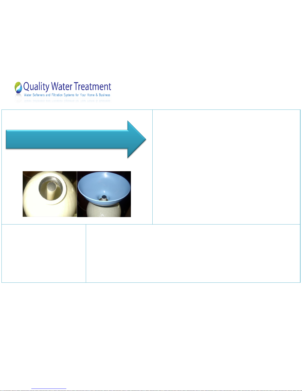
Position your new softener unit where you want it placed for use.
Inside the Softener tank you’ll find a 1.05" gray or white Pvc tube
(called a distributor tube.) If the tube does not already have a cap on
the top use a pvc slip cap or some duct tape to temporarily plug this
tube (this is to keep the resin from going down the tube.) If your
system came with gravel, add the gravel first, then the resin. Use the
included special funnel when adding the resin. This will take about 10
minutes.
After adding the resin, remove the temporary cap, clean the valve
threads with water, and screw the valve on. When screwing the valve
on the tank the tube will slip into the bottom of the valve hole. Note:
No silicone or tape is needed; the valve is o-ring fit and only needs to
be tightened by hand. Do not over tighten.
Assemble all tools
needed for
installation.
If you are using copper you will need a copper cutter, propane tank, soldering torch, flux, wire paper, and
lead free solder.
Now that you have collected the materials and added the resin you are ready to install.
Adding Resin
Page 3 of 17
Copyright © 2012 Quality Water Treatment, All right reserved. rev. 4.19.2013 http:// www.Qualitywatertreatment.com
Fleck 7000 SXT
Please follow the instructions below step by step in order to correctly
complete the installation of your new water softener from Quality Water
Treatment.
Attaching the Bypass
valve
1. Turn off the main water shut off valve.
2. Open all plumbing fixtures in the house including the outside faucets in order to drain the lines.
Unscrewing the aerator screen from your bathroom and kitchen faucets will help drain the lines faster.
3. Cut and remove a 4” section of the water line where the unit is to be installed.
4. Remove the plastic clips that are connected between the plastic bypass and the plastic meter assembly.
Remove the bypass valve from the meter assembly by pulling it away from the meter assembly. Notes: Be
sure to leave the meter assembly in place. If soldering we do not recommend applying heat from a
soldering torch to solder copper pipe to new valve/meter assembly.
5. Solder adapters of your choice to copper tales we provided or glue adapters to pvc tales if you ordered
your system with that option.
6. Once the pieces of 1” or 1 1/4” Adapters of your choice are soldered or glued into the adapters wait until
they are cool enough to touch.
7. Re-attach the plastic bypass valve back onto the valve/meter assembly and secure it with red clips
Begin Installation

Page 4 of 17
Copyright © 2012 Quality Water Treatment, All right reserved. rev. 4.19.2013 http:// www.Qualitywatertreatment.com
Fleck 7000 SXT
Final water line
Installation
1. First, Measure and cut the lengths of pipe you need to plumb the hard water line into your softener unit.
Then do the same for the soft water line that will exit from the softening unit back into the home.
2. The unit will be marked either on the back of the valve body itself with the word “In” and “out” or the top
of the body of the bypass valve assembly will have arrows showing the direction of water flow. “OUT” is
the water entering your house after it passes through the water softener. Shown in Figure 1. PLEASE be
careful to follow these correctly, making sure you plumb the system in the right direction otherwise you
will lose the resin out of your tank into your house lines!
3. Once you have made all the connections put the system in Bypass (holes in the two bypass handles should
be Up and Down)
4. Put the threaded drain line adapter in place (figure 2) using Teflon tape (only) to make sure it’s snug.
Figure 1
Figure 2
Page 5 of 17
Copyright © 2012 Quality Water Treatment, All right reserved. rev. 4.19.2013 http:// www.Qualitywatertreatment.com
Fleck 7000 SXT
5. Now that you have the adapter in place you can attach your drain line. (Do NOT attach your drain line to
the elbow on the brine tank; it will overflow the brine tank). Running the drain line to a house drain such
as where your washing machine drain line goes is an excellent choice, if this is not possible then you can
drain into another area of your choice; Note: Do not run drain line to plants, shrubs, trees or a lawn unless
using potassium chloride instead of rock salt, make sure you have an air gap if going into a pipe. (Air Gap:
Open area where there is no standing water). Your drain line can be elevated up to 5 feet over/above
where it comes out of the valve and up to 100 feet away. Remember to always follow your local codes.
6. Slide a 1/2” hose clamp over the drain line then slide the drain line over drain hose barb. Slide hose clamp
over the drain and barb, tighten the clamp.
7. Plug your power cord into a nearby outlet that is not connected to a switch.
-Continue to page 6 for Brine tank assembly Instructions -
Page 6 of 17
Copyright © 2012 Quality Water Treatment, All right reserved. rev. 4.19.2013 http:// www.Qualitywatertreatment.com
Fleck 7000 SXT
Make sure you have all of the pieces to the brine assembly. The nuts and
ferrules are now combined into one and are usually already attached to the
brine assembly; please check this to make sure.
Brine tank
installation
instructions
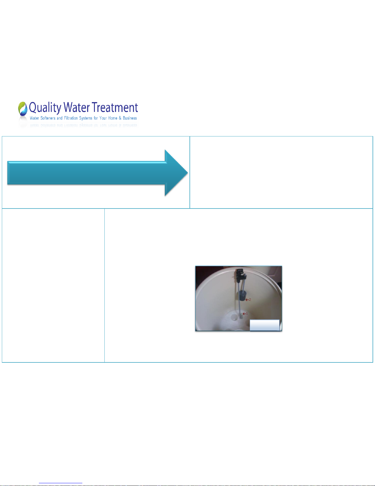
1. The float assembly is a safety float; it only functions if there is a failure in the control valve. This will insure
that the brine tank won’t over flow with water. The safety float DOES NOT dictate the water level in your
brine tank.
2. Measure 10” from the top of the air check valve (shown as #1 in figure 3 below) to the bottom of the float
(shown as #2 in figure 3 below). You may have to gently push the float rod through the rubber gametes to
achieve this, cut any existing rod off.
3. Slide the float assembly into the brine well (shown in figure04 below) and stick the stud into the side hole
on the brine well ( shown in figure 5). Be sure to secure it with the nut we supplied you.
Brine tank assembly
Figure 3
 Loading...