

Fleck 6600, 6665, 6700, 6765 Service Manual
6600, 6665,
6700, 6765
6665
6700
6600 – 6665 – 6700 – 6765

6600 – 6665 – 6700 – 6765
E
N
G
L
I
S
H
EN
FR
DE
ES
NL
1 www.fleck-orderguide.com
SERVICE MANUAL ..................................... 1
MANUEL D’UTILISATION ........................ 34
BEDIENUNGSANLEITUNG ...................... 66
MANUAL DE USO .................................... 98
IT
MANUALE DI USO ................................. 130
HANDLEIDING VOOR GEBRUIK ........... 162
6600 – 6665 – 6700 – 6765

E
N
G
L
I
S
H
TABLE OF CONTENTS
1- VALVE SPECIFICATION ......................................................3
2- GENERAL ADVICE .............................................................4
3- INSTALLATION INSTRUCTIONS .......................................5
4- VALVE OPERATION ............................................................6
5- BASIC PROGRAMMING MODE ....................................... 12
6- ADVANCED PROGRAMMING MODE .............................. 14
7- TROUBLESHOOTING ...................................................... 32
8- POWER HEAD 6600 / 6665 ........................................194
9- POWER HEAD 6700 / 6765 ........................................195
10- VALVE BODY ..................................................................196
11- METER & ACCESSORIES .............................................197
12- DIMENSIONS ................................................................ 198
13- WIRING DIAGRAM .........................................................199
2 www.fleck-orderguide.com
6600 – 6665 – 6700 – 6765
1 - VALVE SPECIFICATION
Installation N° System capacity
Valve serial N°
Tank size
Resin type
Resin volume
Inlet water hardness
Water hardness after mixing valve
Brine tank size
Quantity of salt per regeneration
VALVE TECHNICAL CHARACTERISTICS
VALVE TYPE
6600/1600 6665/1600 6700/1600 6765/1600
TRIGGERING SET REGENERATION
Meter immediate Days
Meter delayed
Timeclock 2 A.M.
REGENERATION TIME
or
a.m./p.m.
REGENERATION CYCLES ACCORDING TO PISTON TYPE
Cycle 1
Cycle 2
Cycle 3
Cycle 4
Cycle 5 (6 cycles valve only)
Cycle 6 (6 cycles valve only)
m
3
°tH
°tH
°tH
litres
Litre
E
N
G
L
I
S
H
Kg
HYDRAULIC SETTINGS
Injector size Pressure regulator
Drain line flow control (DLFC)
Brine line flow control (BLFC) GPM Without
VOLTAGE
24V/50- 60Hz with transformer
Valves complying european regulations:
- Nr. 2004/108/CE, “Electromagnetic compatibility”
- Nr. 2006/95/CE, “Low voltage”
- Nr. D.M. 174/04, Italian regulation
3
GPM 1,4 bar (20 PSI) 2,1 bar (30 PSI)
6600 – 6665 – 6700 – 6765

E
N
G
L
I
S
H
2.1 MANUFACTURER
2 - GENERAL ADVICE
IT IS STRICTLY FORBIDDEN FOR NOT QUALIFIED PERSONAL, TO ACCEDE TO SYSTEM’S INTERNAL PARTS TO
PERFORM ANY KIND OF TECHNICAL ACTION.
Pentair Manufacturing Italy Srl
Via Masaccio, 13
56010 Lugnano di Vicopisano (PI) – Italy
2.2 WARNINGS
The manufacturer will not be held liable for any damages to people or properties resulting from an improper use of
the device not compliant with the following instructions.
Whenever this guide doesn’t clarify all doubts about installation, service or maintenance, please contact the technical
support of the company that has installed the device.
Device installation must be done by a qualified technician according to the current standards and regulations, using
tools compliant with a device safety use and referring to that technician also for device maintenance.
In case of out of order or malfunction, before performing any kind of action on the device, please ensure to have
disconnected the transformer from the power source, to shut off inlet water supply to the valve and to drain water
pressure opening a tap down-line of the valve.
2.3 INTENDED USE
The device is intended for residential, commercial or light industry environment (ref. EN 50081-1) use only and it is
purpose-built for treatment and softening of water coming from supply network.
2.4 TECHNICAL DATA
Transformer: 230Vac, 50/60Hz, 15VA, Class II.
Controller: 24Vac, 50/60Hz, 5W, Class III.
The device must only be used with the transformer provided in order to guarantee safety voltage supply.
2.5 WATER PRESSION
A minimum of 1,4 bar of water pressure is required for the regeneration valve to operate effectively. Do not exceed
8,5 bar; if you face this case, you should install a pressure regulator upstream the system.
2.6 ELECTRICAL CONNECTION
An uninterrupted current supply is required. Please make sure that your voltage supply is compatible with your unit
before installation. If the electrical cable is damaged, it must imperatively be replaced by a qualified personal.
2.7 ExISTING PLUMBING
Existing plumbing should be in a good shape and free from limescale. In doubt, it is preferable to replace it. The installation of a pre filter is always advised.
2.8 BY-PASS
Always provide a by pass valve for the installation, if the unit is not equipped with one.
2.9 WATER TEMPERATURES
Water temperature is not to exceed 43°C, and the unit cannot be subjected to freezing conditions.
2.10 DISINFECTION OF WATER CONDITIONERS
The materials of construction of the modern water conditioner will not support bacterial growth, nor will these
materials contaminate a water supply. In addition, during normal use, a conditioner may become fouled with organic
matter, or in some cases with bacteria from the water supply. This may result in an off-taste or odor in the water.
Thus, your conditioner may need to be disinfected after installation. Some conditioners will require periodic disinfection during their normal life. Consult your installing dealer for more information on disinfecting your conditioner.
2.11 ENVIRONMENTAL CONDITIONS
• Indoor Use Only
• Altitude up to 2000m
• Temperature from 5°C to 40°C
• Maximum relative humidity 80% for temperatures up to 31°C decreasing linearly to 50% relative humidity at 40°C
• Mains supply voltage fluctuations up to ±10% of the nominal voltage
4
6600 – 6665 – 6700 – 6765

3 - INSTALLATION INSTRUCTIONS
3.1 Install the softener pressure vessel(s) in a chosen place on a flat firm surface.
3.2 During cold weather, it is recommended to bring the valve back to room temperature before operating.
3.3 All plumbing for water inlet, distribution and drain lines should be done correctly in accordance with legislation
in force at the time of installation. Install without tension or bending stresses.
3.4 The distribution tube should be cut flush with the top of the tank. Slightly bevel the ridge in order to avoid
deterioration of the seal whilst fitting the valve.
3.5 Lubricate the distribution tube joint and the joint with a 100% Silicon lubricant. Never use other types of
greases that may damage the valve.
3.6 All soldering on main plumbing and to the drain line should be done before fitting the valve. Failing to do so can
generate irreversible damages.
3.7 Use Teflon ® tape if necessary in order to seal between the drain fitting and the outlet flow control.
3.8 On units with by-pass, place in by-pass position. Turn on the main water supply. Open a cold water tap nearby
and let run a few minutes or until the system is free from foreign material (usually solder) that may have
resulted from the installation. Once clean, close the water tap.
3.9 Place the by-pass in service position and let water flow into the mineral tank. When water flow stops, slowly
open a cold water tap nearby and let run until the air is purged from the unit.
3.10 Plug the valve to a power source. Check that the valve is in service position
3.11 Fill approximately 25mm of water above the grid plate, (if used). Otherwise, fill to the top of the air check in
the brine tank. Do not add salt to the brine tank at this time.
3.12 Initiate a manual regeneration, bring the valve into « brine draw and slow rinse position » in order to draw
water from the brine tank until the blockage of the air check; the water level will be approximately in the middle
of the air check.
3.13 Open a cold water tap and let the water run in order to drain the air out of the circuit.
3.14 Bring the valve in brine refill position and let it get back to service position automatically.
3.15 Now you can add salt to the brine tank, the valve will operate automatically.
E
N
G
L
I
S
H
5
6600 – 6665 – 6700 – 6765
E
N
G
L
4 - VALVE OPERATION
I
S
H
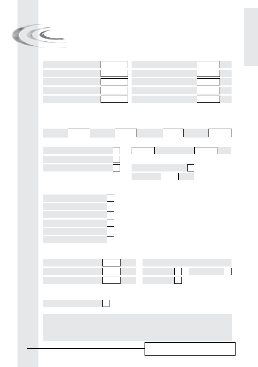
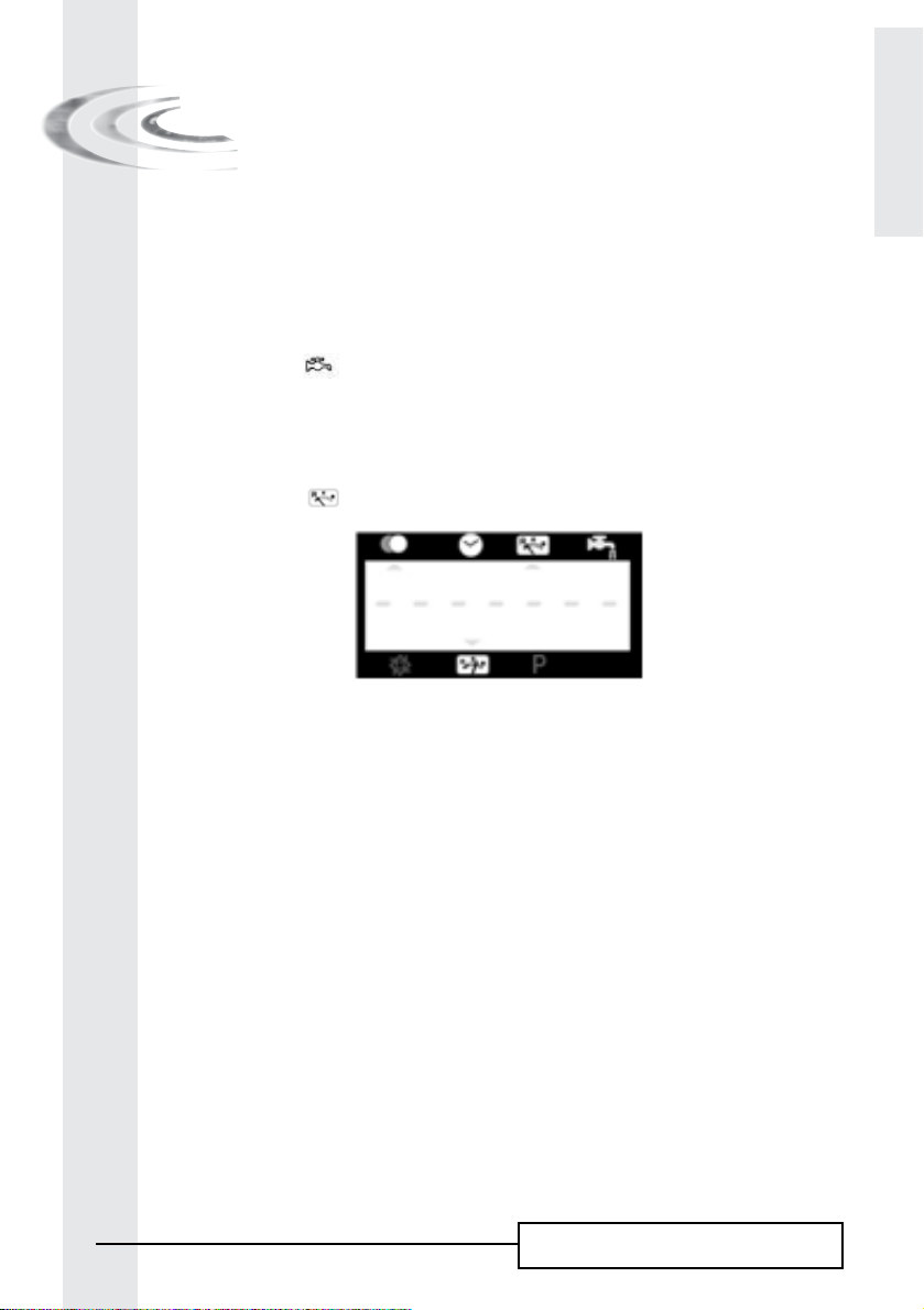
4.1 VALVE 6600 PRESENTATION
Service Indicator
Valve in service : arrow on Regeneration
tonight : flashing arrow
Regeneration indicator:
Arrow on
Time of day display indicator time
of day display: arrow on
Volume remaining
display indicator : Arrow on
Reserve indicator :
Volume remaining at or below the
reserve: flashing arrow
Flow indicator :
Arrow flashes with water
flow
Program display indicator :
Arrow on
Up and Down set button
Program button
Extra cycle button
6
6600 – 6665 – 6700 – 6765
4 - VALVE OPERATION
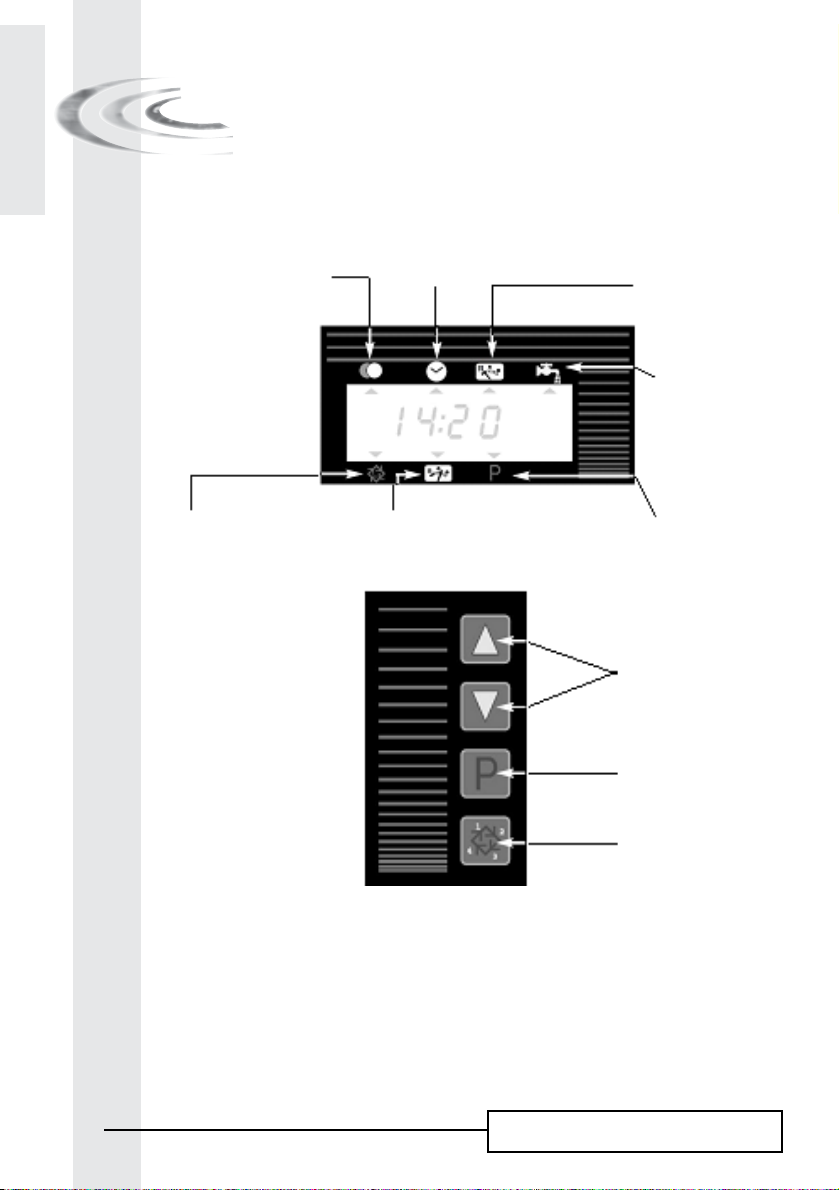
4.2 VALVE 6700 PRESENTATION
E
N
G
L
I
S
H
Service Indicator:
Valve in service : arrow on
Regeneration tonight: flashing arrow
Regeneration indicator: Arrow on
Extra cycle button
Time of day display indicator
Time of day display: arrow on
Volume remaining display indicator:
Arrow on
Up and Down set
button
Reserve indicator
Volume remaining at or below the reserve : flashing
arrow
Flow indicator
Arrow flashes with water flow
Program display indicator: Arrow on
Program button
Backwash
Valve capacity
Brine draw/slow rinse
Up flow
Hardness Regeneration time
Brine draw/slow rinse
Down Flow
Rapid rinse Brine refill
Note: during programming and during regeneration, the red led next to the appropriate symbol turns on
7
6600 – 6665 – 6700 – 6765

E
N
G
L
4 - VALVE OPERATION
I
S
H
4.3 BUTTON FUNCTION
4.3.1 ExTRA CYCLE BUTTON
Pressing this button will initiate a manual regeneration.
1. With timeclock or meter delayed regeneration, an extra regeneration will occur at the set regeneration time.
Press this button for 5 seconds, a regeneration will force to occur immediately.
2. With meter immediate regeneration, an extra regeneration will occur immediately.
4.3.2 PROGRAM BUTTON:
This button is used by the installer during the valve programming. It is used to enter the programming modes,
and to go from one setting to the next one.
4.3.3 SET BUTTON: AND
This button is used to set the current time of day, adjust the parameter value during the valve programming and
the time remaining in a regeneration cycle.
8
6600 – 6665 – 6700 – 6765
4 - VALVE OPERATION
4.4 OPERATION DURING SERVICE
E
N
G
L
I
S
H
4.4.1 METERED VALVE
In service the time of day alternates being viewed with the volume remaining. The water flow through the
unit is indicated by the meter arrow
counts down with the consumption of treated water.
(1)
under the pictogram
4.4.1A METER DELAYED REGENERATION
When the volume remaining reaches the reserve capacity (calculated by the electronics), the reserve arrow
flashes as an indication. The regeneration will initiate at the pre-set regeneration time.
When the reserve capacity is exhausted, the display will show a succession of dash and the regeneration will
initiate at the pre-set regeneration time.
(2)
under the pictogram
(1)
that flashes in a direct relationship to flow rate. The volume remaining
(2)
4.4.1B METER IMMEDIATE REGENERATION
When the volume remaining reaches zero, the regeneration starts immediately.
4.4.1C 6 CYCLES MODE (SPECIAL MODE USED FOR “WATERFALL
SYSTEMS DVGW”)
This valve is in immediate and upflow regeneration,with chlorination and “pause-vacancy” position. The
particularity of the “pause-vacancy” position :
•Whenthereisnotaflowratedetectedfor4daysrunning:
- the valve initiates a regeneration and returns in service
•Whenthereisnotstillaflowratedetectedfornext4daysrunning:
- the valve initiates a regeneration and stops at the “pause-vacancy” position
- the valve will end the regeneration and return in service only when there will be a flow rate
detected.
4.4.1D VARIABLE BRINING MODE (ONLY METER DELAYED UP
FLOW)
The valve will determine that a regeneration is required when the volume remaining drops to the reserve
capacity. The regeneration will begin immediately at the set regeneration time. The volume of the brine
depends on the volume of the softened water consummate; therefore the time of the brine refill is calculated
by the electronic.
9
6600 – 6665 – 6700 – 6765

E
N
G
L
4 - VALVE OPERATION
I
S
H
4.4.2 TIMECLOCK VALVE
In service, the time of day is viewed all the time. The valve operates normally until the pre-set number of days
since the last regeneration is reached. Once this occurs, regeneration will start immediately at the pre-set
regeneration time.
4.4.3 VALVE WITH REGENERATION DAY OVERRIDE
When the valve has reached its set days since regeneration override value, the regeneration will initiate
immediately or delayed at the pre-set regeneration time regardless of the volume remaining.
10
6600 – 6665 – 6700 – 6765
4 - VALVE OPERATION
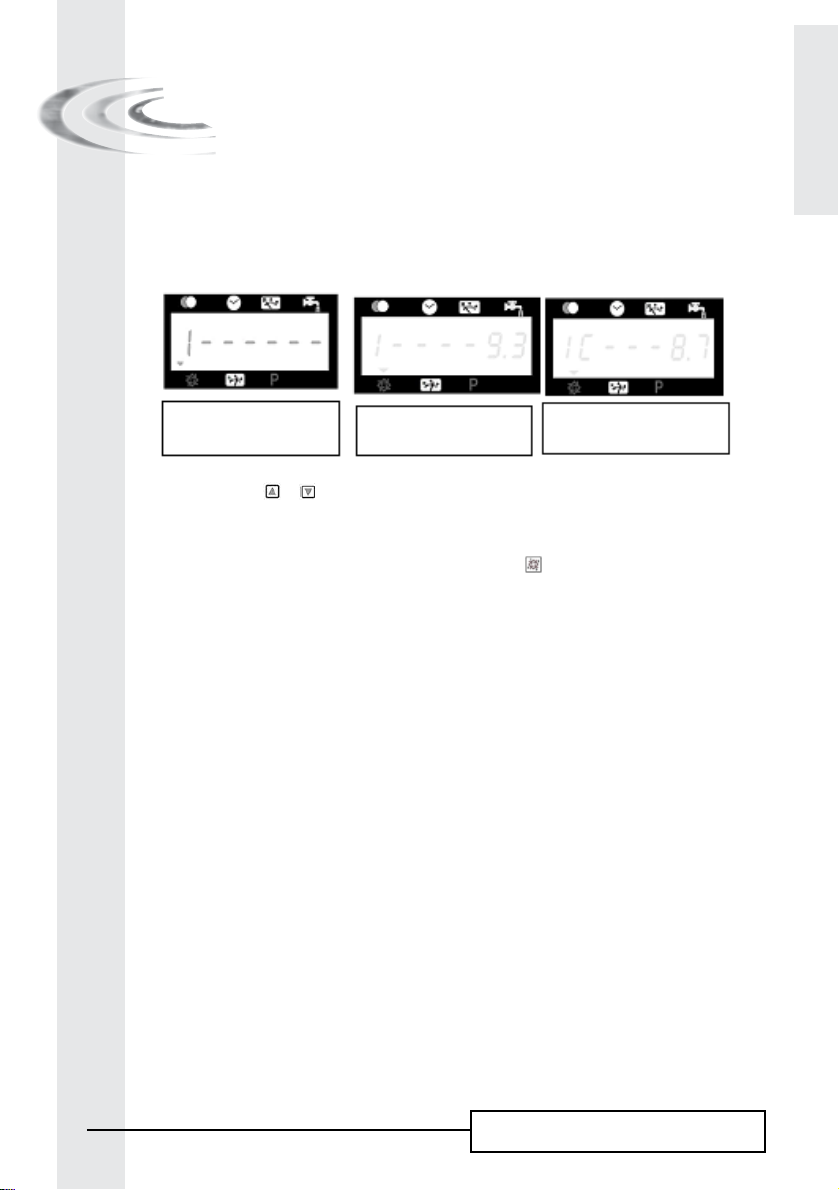
4.5 OPERATION DURING REGENERATION
In regeneration, the valve displays what regeneration cycle has been reached and the time remaining in that
cycle. The time remaining is in minutes and tenth of minutes. Once the cycle time reaches zero, the valve
drives to the next cycle.
E
N
G
L
I
S
H
The valve is advancing to
cycle 1, number 1 is flashing
Pressing the button or during regeneration cycle will adjust the remaining time. The regeneration cycle
programming will not be changed.
The valve is in cycle 1, 9,3 min
remaining in that cycle
For valves with chlorinator,the letter C
indicates its functioning
4.6 ADVANCE TO THE NExT REGENERATION CYCLE
To advance to the next regeneration cycle position, push the button . This action won’t have any effect if
the valve is advancing to the next cycle.
4.7 OPERATION DURING A POWER FAILURE
During a power failure all displays turn off and the regeneration cycles are delayed. The electronics continues
to operate normally until the line power is restored or until the capacitors stored energy is empty.
1. I If the capacitor isn’t fully discharged during the power failure, the electronics continues to operate
normally without the loss of data until the line power is restored.
2. If the capacitor is discharged during the power failure, the electronics stores the current time of day, the
remaining, the regeneration cycle status and the various diagnostic displays. To indicate this type of failure,
the time of day will flash to inform that this display and the volume remaining may be incorrect.
11
6600 – 6665 – 6700 – 6765
E
N
G
L
I
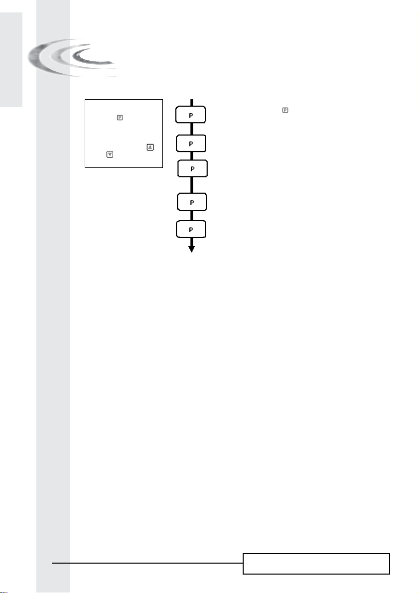
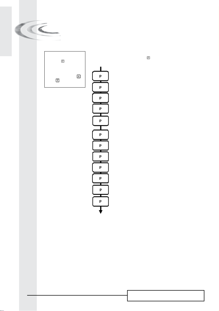
5 - BASIC PROGRAMMING MODE
6600 / 6665
S
H
Note :
1. Push the button once
per display.
2. Option settings may be
changed by pushing the
and set buttons
The valve is in service position. To enter in the basic programming
mode, push and hold the button for 5 seconds.
5.1. Water Hardness in °tH
Not viewed in timeclock regeneration mode
Ex.: 30 °tH [H - - - -30]
5.2. Water Hardness after mixing valve in °tH
Not viewed in timeclock regeneration mode
Ex.: 6 °tH [P - - - -6]
5.3. Regeneration time
Not viewed in immediate regeneration mode
Ex.: 02:00 [- - 2:00 -]
Basic programming mode exit.
The valve returns in normal operation.
12
6600 – 6665 – 6700 – 6765
5 - BASIC PROGRAMMING MODE
6600 / 6665
This level includes the functioning parameters of the softener related to the site conditions.
E
N
G
L
I
S
H
ENTERING BASIC PROGRAMMING MODE
A- The valve is in service position. Press the button for 5 seconds. The program arrow turns on and the
first display viewed is used to set the inlet water hardness.
B- The
and set buttons are used to set the parameter values of different displays.
C- Passing to the next display, push the
Note: depending on the current programming, certain displays will not be viewed or set.
button.
5.1 WATER HARDNESS
Not viewed in timeclock regeneration mode or when the volume override is activated.
The unit of measure used for the parameter is °tH(1). Adjust the value with the and set buttons.
Ex.: Hardness 30 °tH
(1)
[H - - - - 30]
5.2 WATER HARDNESS AFTER THE MIxING VALVE (P)
Not viewed in timeclock regeneration mode, with the volume override activated, or in US format, or if 8 set
(2)
on 1
.
Press button. The letter “P” identifies this parameter. The unit of measure is the °tH(1). Adjust the value
with the
Ex.: Hardness after the mixing valve 6 °tH
and set buttons.
(1)
: [P - - - - 6]
5.3 REGENERATION TIME
Not viewed in meter immediate regeneration mode.
Press the button. Set the regeneration time with the and set buttons.
Ex.: Regeneration at 2:00 A.M. [--2:00--]
ExITING BASIC PROGRAMMING MODE
Press once again the button. the electronics returns in service.
(1) The unit of measure depends on the display format chosen.
All examples above are based on the cubic meter format -see point 6.17.
(2) See point 6.24
13
6600 – 6665 – 6700 – 6765
E
N
G
L
I
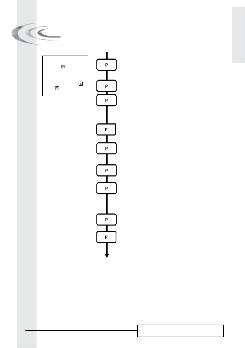
6 - ADVANCED PROGRAMMING MODE
6600 / 6665
S
H
Note :
1. Push the button once
per display.
2. Option settings may be
changed by pushing the
and set buttons
The valve is in service position set at 12:01. To enter in the complete
level, push and hold the button for 5 seconds.
The board will show first all parameters of the basic programming
mode, and then following settings:
6.1. Flow rate (Fr) in l/min
Ex.: 8,6 l/mn not adjustable [Fr - - 8.6]
6.2. Days since the last regeneration (d)
Ex.: 2 days not adjustable [d - - - - 2]
6.3. Prior service volume used in litre (1)
Ex.: 3483 l not adjustable [E - -3483]
6.4. Reserve capacity (rc) in litre (1)
Ex.: 852 l not adjustable [rc - - 852]
6.5. Previous days water usage (Pd) in litre (1)
Ex.: 284 l not adjustable [Pd - -28.4]
6.6. System capacity in m3 °tH (c)
Ex.: 100 m3 °tH [C- - - 100]
6.7. Cycle #1 :
Ex.: 6 minutes [1 - - - 6.0]
6.8. Cycle #2 : [2 - - 60.0]
Ex.: 60 minutes
6.9. Cycle #3 : [3 - - 10.0]
Ex.: 10 minutes
6.10. Cycle #4 : [4 - - 12.0]
Ex.: 12 minutes
6.11. Cycle #5 [5 - -OFF]
Only for 6 cycles mode
6.12. Cycle #6 [6 - -OFF]
Only for 6 cycles mode
Note : not viewed if cycle #5 is set on OFF.
(1)
(1)
(1) The unit of measure depends on the display format chosen.
All examples above are based on the cubic meter format (see point 6.17).
14
6600 – 6665 – 6700 – 6765
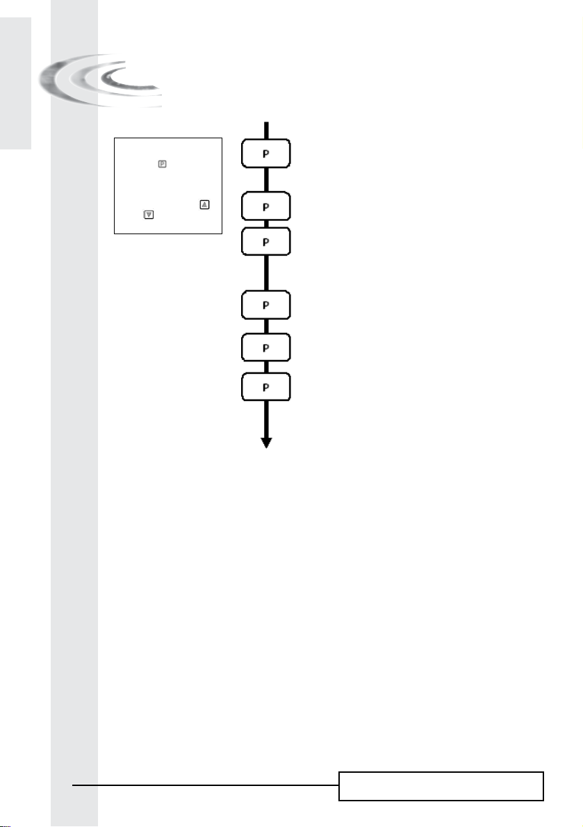
6 - ADVANCED PROGRAMMING MODE
6600 / 6665
Note :
1. Push the button once
per display.
2. Option settings may be
changed by pushing the
and set buttons
6.13. Chlorine cell activation (J)
Ex.: - Chlorination activated during the cycle 1 [J - - - - -1]
- No chlorination [J- - -OFF]
6.14 Chlorine cell power on duration
Ex: 20 mn [Jd- - - 20]
6.15. Regeneration day override (A)
Ex.: - Override every 7 days [A - - - - 7]
- Cancel setting [A - -OFF]
Note: in timeclock regeneration, never
cancel this setting.
E
N
G
L
I
S
H
6.16. Volume override (b) in litre
Ex.: - Regenerate every 2000 l [b- - 2000]
6.17. Display format (U)
Ex.: - Litre format [U - - - - - 2]
- Cubic meter format [U - - - - - 4]
6.18. Valve Type (o)
Ex.: Valve 6600/6665/6665 6 cycles [o - - - - - 1]
6.19. Regeneration type (7)
Ex.: - Timeclock [7 - - - - - 1]
- Meter immediate [7 - - - - - 2]
- Meter delayed [7 - - - - - 3]
- Variable Brining [7 - - - - - 4]
- 6 cycles [7 - - - - - 7]
6.20. Volume of resin
(only available with variable brining mode)
Ex. : 15 litres [7r - - - 15.0]
6.21. Salt setting
(only available with variable brining mode)
Ex.: 120 g of salt/litre of resine [7d - - 120]
(1)
(1) The unit of measure depends on the display format chosen.
All examples above are based on the cubic meter format (see point 6.17).
15
6600 – 6665 – 6700 – 6765
E
N
G
L
I
6 - ADVANCED PROGRAMMING MODE
6600 / 6665
S
H
Note :
1. Push the button once
per display.
2. Option settings may be
changed by pushing the
and set buttons
6.22. BLFC size (only available with variable brining mode)
See the label on the injector housing [7b - -X.XX]
6.23. Flow meter size (F)
Ex.: Standard 3/4” [F - - - - - 1]
6.24. Mixing valve location (8)
Ex.: - No mixing valve [8 - - - - - 1]
- Mixing valve before flow meter [8 - - - - - 2]
- Mixing valve after flow meter [8 - - - - - 3]
6.25. System type (9)
Ex.: - System type #4 : single electronic [9 - - - - - 4]
6.26. Program lockout (Pl)
Ex.: - Cancel lockout [Pl - - - OFF]
- Lockout active [Pl - - - - ON]
Advanced programming mode exit.
The valve returns in normal operation
16
6600 – 6665 – 6700 – 6765

6 - ADVANCED PROGRAMMING MODE
6600 / 6665
Setting up the valve during manufacturing of the softener requires access to the advanced programming.
This level includes the functioning parameters of the softener related to actual system configuration.
E
N
G
L
I
S
H
ENTERING ADVANCED PROGRAMMING MODE
A- Set valve at 12:01, press the button for 5 seconds. The program arrow turns on and the first display
viewed is used to set the inlet water hardness. Then press the
B- The
and set buttons are used to set the parameter values of different displays.
C- Passing to the next display, push the
Note: depending on the current programming, certain displays will not be viewed or set.
button.
button for 5 seconds.
6.1 FLOW RATE (Fr) (1):
Not viewed in timeclock regeneration mode.
Press the button .This display is identified by the letters “Fr”. This first display is the current flow rate of
treated water. The unit of measure used depends on the display format chosen
Ex.: 8,6 l/min [Fr - - - 8.6]
.
(1)
6.2 DAYS SINCE THE LAST REGENERATION (d):
Press the button .This parameter is identified by the letter “d”. This display shows the number of days
recorded since the last regeneration. This display is used as an aid in the valve maintenance and is not an
option setting.
Ex.: 2 days [d - - - - - 2]
6.3 PRIOR SERVICE VOLUME USED (E):
Not viewed in timeclock regeneration mode.
Press the button . This display is identified by the letter “E”. This display shows the amount of water
used since the last regeneration. This display is used as an aid in the valve maintenance and is not an option
setting.
The unit of measure used depends on the display format chosen(1).
Ex.: 58,6 m
3 (1)
[E - - - 58.6]
6.4 RESERVE CAPACITY (rc):
Not viewed in timeclock or immediate regeneration mode.
Press the button . This parameter is identified by the letters “rc”. This display shows the reserve capacity
calculated by the electronic for the present day. This display is used as an aid in the valve maintenance and is
not an option setting. The unit of measure used depends on the display format chosen
Ex.: 24,6 m
3(1)
[rc - - 24.6]
.
(1)
(1) The unit of measure depends on the display format chosen.
All examples above are based on the cubic meter format (see point 6.17).
17
6600 – 6665 – 6700 – 6765

E
N
G
L
I
6 - ADVANCED PROGRAMMING MODE
6600 / 6665
S
H
6.5 PREVIOUS DAYS WATER USAGE (Pd):
Not viewed in timeclock regeneration mode.
Press the button. This display is identified by the letters “Pd”. This display shows the previous days water
usage recorded. This display is used as an aid in the valve maintenance and is not an option setting. The unit of
measure used depends on the display format chosen
Ex.: 28,4 m3(1) [Pd - - 28.4]
.
(1)
6.6 SYSTEM CAPACITY
Press the button . The unit of measure used depends on the display format chosen
set the capacity of the softener. If required, the electronics will calculate a reserve. Adjust the value with the
and set buttons.
Ex.: Capacity 1200 m3° tH
(1)
: [- - - -1200]
. This display is used to
(1)
6.7 REGENERATION CYCLE PROGRAMMING
to
The cycle 6 will not be viewed if the cycle 5 is cancelled [5 --- O F F ].
6.12 Press the button . The next displays are part of a series of option settings used to program the regeneration
cycles. Up to 6 cycles can be programmed. Each display is used to set the duration time (in minute) of that
cycle in the regeneration.
The first display in the series is regeneration cycle 1, example: Backwash
Ex.: - Cycle 1 (Backwash): 8 minutes [1 - - - 8.0]
- Cycle 4 (Brine refill): 8.4 minutes (8 min and 24 s.) [4 - - - 8.4]
6.13 CHLORINE CELL ACTIVATION (J):
Press the button . This display is identified by the letter “J”. This display is used to activate the chlorine
function during cycle 1.
Ex.: - No chlorinator installed [J- - - OFF]
- Chlorinator to turn on during the cycle 1 [J- - - - - -1]
6.14 CHLORINE CELL POWER DURATION
Press the button . This display is identified by the letter “dJ”. This display is used to set the chlorine cell
power on duration.
Note: During a regeneration with the chlorine cell set, for example cycle 2, the regeneration display
will show: [2C - - 38.2]
(1) The unit of measure depends on the display format chosen.
All examples above are based on the cubic meter format (see point 6.17).
18
6600 – 6665 – 6700 – 6765

6 - ADVANCED PROGRAMMING MODE
6600 / 6665
6.15 REGENERATION DAY OVERRIDE (A)
In timeclock regeneration mode, a value must be set.
Press the button .This parameter is identified by the letter “A”. This option is used to set the regeneration
day override option setting. This override setting determines the maximum amount of time (in days) the
softener can be in service without a regeneration, regardless of the volume of water used or the lack of a
sensor signal. The regeneration begins at the set regeneration time.
Ex.: - Override every 7 days [A - - - - - 7]
- Option cancelled [A - - - OFF]
E
N
G
L
I
S
H
6.16 VOLUME OVERRIDE (b)
Not viewed in time clock regeneration mode.
Press the button . This display is identified by the letter “b”. The volume override option is used to set the
maximum amount of water that can be used before a regeneration cycle is called for.
This option is typically used to bypass standard reserve or capacity calculations made by the electronics.
When this feature is used with meter delayed regeneration systems, it will be up to the installer to determine
a reserve capacity and subtract it from the calculated full capacity. The unit of measure depends on the
display format chosen
Ex.: Override every 2.6 m3(1) [b - - 2600]
(1)
.
6.17 DISPLAY FORMAT (U)
Press the button . This display is identified by the letter “U”. One of five following display
formats can be used. The current format used is the cubic meter (U4): the volume is in cubic
3
meter (m
), the flow rate in litre per minute (l/min), 24 hours timekeeping format, water hardness in French
degrees or °tH degrees and the sys-tem capacity in °tH degrees cubic meter (°tH x m
The format used for small volume is the litre (U2): the volume is in litre (l), the flow rate in litre per minute (l/
min), 24 hours timekeeping format, water hardness in French degrees or °Th degrees and the system capacity
in °tH degrees cubic meter (°tH x m
Ex.: - US format (not used) [U - - - - - 1]
- Litre format [U - - - - - 2]
- Standard metric (not used) [U - - - - - 3]
- Cubic meter format [U - - - - - 4]
Note: for further information, please contact our technical support.
3
).
6.18 VALVE TYPE (o)
Press the button. This parameter is identified by the letter “o”. This display is used to set the type of
valve used. The only possible settings are #1 and #2 for 6600 and 6700 valve family.
Ex.: - 6600 / 6665 [o - - - - - 1]
- 6700 / 6765 [o - - - - - 2]
3
).
(1) The unit of measure depends on the display format chosen.
All examples above are based on the cubic meter format (see point 6.17).
19
6600 – 6665 – 6700 – 6765

E
N
G
L
I
6 - ADVANCED PROGRAMMING MODE
6600 / 6665
S
H
6.19 REGENERATION TYPE (7)
Press the button . This display is identified by the number “7”. This option is used to set the regeneration
type. There are several possible option settings:
- Timeclock: the electronics determines that regeneration is required when the set regeneration time has been
reached. The regeneration day override setting (see point 2.10) determines the number of days between two
regenerations.
[7 - - - - - 1]
- Meter immediate: the electronics determines that a regeneration is required when the available volume of
softened water drops to zero. The regeneration begins immediately. [7 - - - - - 2]
- Meter delayed: the electronics determines that a regeneration is required when the available volume of
softened water drops to the reserve capacity. The regeneration begins immediately at the set regeneration
time only when the service flow has not been detected. With service flow, the regeneration will be delayed
in two 10 minute sections. After then if there is always a flow, the regeneration begins immediately. There
will be not a delay if the reserve capacity is zero. [7 - - - - - 3]
- Meter delayed variable brining: Only available for UF valve.
The electronics displays and initiates regeneration as in meter delayed mode. In variable brining mode the first
cycle is brine refill, and second one is vacancy. All other cycles follow standard order. Electronic calculates first
cycle duration considering previous water usage and uses setting 7r, 7d & 7b. [7 - - - - - 4]
- Meter Immediate with vacation mode (6 cycles mode): only available for UF valve.
The electronics displays and initiates regeneration as in meter immediate mode. However the electronics
requires a day override setting. However a day override setting is required and cycles sequence is different. The
regeneration cycles are following: brine draw, vacancy, slow rinse, backwash, rapid rinse, brine refill. The valve
will stay in vacancy if there hasn’t been any consumption between the 2 last regenerations. The electronics will
switch to the next cycle if flow usage is detected. [7 - - - - - 7]
Note: for the following options, please contact our technical support.
- Sensor immediate regeneration [7 - - - - - 5]
- Sensor delayed regeneration [7 - - - - - 6]
6.20 VOLUME OF RESIN (7r)
Press the button. This display is available only with variable brining mode. This display is identified by “7r”.
This parameter is used to set volume of resine. [7r - - 15.0]
6.21 SALT SETTING (7d)
Press the button. This display is available only with variable brining mode. This display is identified by
“7d”. This parameter is used to set salt ratio. [7d - - 120]
6.22 BLFC SIIZE (7b)
Press the button. This display is available only with variable brining mode. This display is identified by
“7b”. This parameter is used to set the BLFC size. [7b - - 0.25]
20
6600 – 6665 – 6700 – 6765

6 - ADVANCED PROGRAMMING MODE
6600 / 6665
6.23 FLOW METER SIZE (F)
Not viewed in timeclock regeneration mode.
Press the button. This parameter is identified by the letter “F”. This option is used to set the flow meter size.
Seven settings are possible. The only possible setting is #1 for 6600/6700 valve family:
Standard 3/4” [F - - - - - 1]
E
N
G
L
I
S
H
6.24 MIxING VALVE LOCATION (8)
Not viewed in timeclock regeneration mode.
Press the button. This display is identified by the number “8”. This option is used to indicate where the
mixing valve is located. Three settings are possible:
No mixing valve [8 - - - - - 1]
Mixing valve before flow meter [8 - - - - - 2]
Mixing valve after flow meter [8 - - - - - 3]
6.25 SYSTEM TYPE (9)
With 6600/6700 valve family, the only possible setting is 4. [9 - - - - - 4]
6.26 PROGRAM LOCKOUT (PL)
Press the button. This display is identified by the letters “Pl”. This display is used to prevent certain
programming displays from being viewed or set. Two settings are available:
Protection cancelled [Pl - - - OFF]
Protection active [Pl - - - - On]
The program lockout can be cancelled by pressing the button
ATTENTION: press the button for 25 seconds when the program lockout is not activated will erase
all previous display setting; the electronic will reset to default values. The electronic programming
will have to be completely redone.
for 25 seconds.
ExITING THE ADVANCED PROGRAMMING MODE
Press again the button, the electronic comes back in service.
Note: for further information, please contact our technical support.
21
6600 – 6665 – 6700 – 6765
E
N
G
L
I
7 - BASIC PROGRAMMING MODE
6700 / 6765
S
H
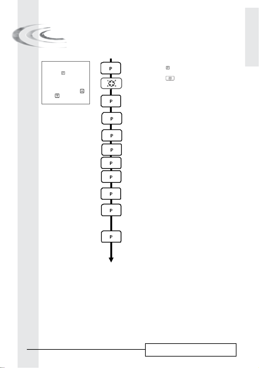
Note :
1. Push the button once
per display.
2. Option settings may be
changed by pushing the
and set buttons
The valve is in service position. To enter in the basic programming
mode, push and hold the button for 5 seconds.
7.1. Water Hardness in °tH
Not viewed in timeclock regeneration mode
Ex.: 30 °tH [H - - - -30]
7.2. Water Hardness after mixing valve in °tH
Not viewed in timeclock regeneration mode
Ex.: 8 °tH [P - - - -8]
7.3. System capacity in m3 °tH
Not viewed in timeclock regeneration mode
Ex.: 60 m3 °tH [- - - -60]
7.4. Regeneration time
Not viewed in immediate regeneration mode
Ex.: 2:00 AM [ - -2:00 -]
Regeneration cycle time setting
7.5. Cycle #1
Ex.: 10 minutes [1 - - 10.0]
7.6. Cycle #2
Ex.: 60 minutes [1 - - 60.0]
7.7. Cycle #3
Ex.: 10 minutes [1 - - 10.0]
7.8. Cycle #4
Ex.: 12 minutes [1 - - 12.0]
7.9. Cycle #5
Only for 6 cycles mode
Ex.: Not used [5 - - OFF]
7.10. Cycle #6
Only for 6 cycles mode
Ex.: Not used [6 - - OFF]
Note: not viewed if cycle #5 is set on OFF]
22
Basic programming mode exit.
The valve returns in normal operation.
6600 – 6665 – 6700 – 6765

7 - BASIC PROGRAMMING MODE
6700 / 6765
This level includes the functioning parameters of the softener related to the site conditions.
E
N
G
L
I
S
H
ENTERING BASIC PROGRAMMING MODE
A- The valve is in service position. Press the button for 5 seconds. The program arrow turns on and the first
display viewed is used to set the inlet water hardness.
B- The
and set buttons are used to set the parameter values of different displays.
C- Passing to the next display, push the
Note: depending on the current programming, certain displays will not be viewed or set.
button.
7.1 WATER HARDNESS
Not viewed in timeclock regeneration mode or when the volume override is activated.
The unit of measure used for the parameter is °tH
Ex.: Hardness 30 °tH(1) [H - - - - 30]
(1)
. Adjust the value with the and set buttons.
7.2 WATER HARDNESS AFTER THE MIxING VALVE (P)
Not viewed in timeclock regeneration mode, with the volume override activated, or in US format, or if 8 set
(2)
on 1
.
Press button. The letter “P” identifies this parameter. The unit of measure is the °tH(1). Adjust the value
with the
Ex.: Hardness after the mixing valve 6 °tH(
and set buttons.
1)
: [P - - - - 6]
7.3 SYSTEM CAPACITY
Press the button . The red led next to the symbol turns on. The unit of measure used depends on the
display format chosen(1). This display is used to set the capacity of the softener. If required, the electronics
will calculate a reserve. Adjust the value with the
Ex.: Capacity 1200 m3° tH
(1)
: [- - - -1200]
and set buttons.
7.4 REGENERATION TIME
Not viewed in meter immediate regeneration mode.
Press the button. Set the regeneration time with the and set buttons.
Ex.: Regeneration at 2:00 A.M. [--2:00--]
(1) The unit of measure depends on the display format chosen.
All examples above are based on the cubic meter format (see point 6.17).
23
6600 – 6665 – 6700 – 6765

E
N
G
L
I
S
H
7.5 REGENERATION CYCLE PROGRAMMING
7 - BASIC PROGRAMMING MODE
6700 / 6765
to
The cycle 6 will not be viewed if the cycle 5 is cancelled [5 --- O F F ]
7.10 Press the button . The next displays are part of a series of option settings used to program the regeneration
cycles. Up to 6 cycles can be programmed. A led identifies only the 4 first cycles. Each display is used to set
the duration time (in minute) of each regeneration cycle.
The first display in the series is regeneration cycle 1, example: Backwash
Ex.: - Cycle 1 (Backwash): 8 minutes [1 - - - 8.0]
- Cycle 4 (Brine refill): 8.4 minutes (8 min and 24 s.) [4 - - - 8.4]
ExITING BASIC PROGRAMMING MODE
Press once again the button. the electronics returns in service.
24
6600 – 6665 – 6700 – 6765
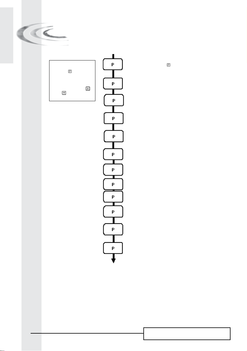
8 - ADVANCED PROGRAMMING MODE
6700 / 6765
Note :
1. Push the button once
per display.
2. Option settings may be
changed by pushing the
and set buttons
The valve is in service position. To enter in the advanced programming
mode, push and hold the button for 5 seconds.
Then depress the button
You are in the advanced programming mode.
8.1. Flow rate (Fr) in l/min
Not viewed in timeclock regeneration mode
Ex.: 8,6 l/min not adjustable [Fr - - 8.6]
8.2. Days since the last regeneration (d)
Not viewed in timeclock regeneration mode
Ex.: 2 days not adjustable [d - - - - 2]
8.3. Prior service volume used in litre
Ex.: 3483 l not adjustable [E - -3483]
8.4. Reserve capacity (rc) in litre
Ex.: 852 l not adjustable [rc - - 852]
8.5. Previous days water usage (Pd) in litre
Ex.: 284 l not adjustable [Pd - -284]
8.6. Chlorine cell activation (J)
Ex.: - Chlorinating activated during the cycle 1 [J - - 1]
- No chloration [J - - OFF]
8.7. Chlorine cell power on duration
Ex.: 20 mn [Jd- - - 20]
8.8. Regeneration day override (A)
Ex.: - Override every 7 days [A - - - - 7]
- Cancelled setting [A - -OFF]
Note: in timeclock regeneration, never
cancel this setting.
8.9. Volume override (b) in litre
Ex.: Regenerate every 5000 litres [b- - 5000]
Note: if b is set, water hardness and system capacity are not viewed.
for 5 seconds.
(1)
(1)
(1)
(1)
E
N
G
L
I
S
H
(1) The unit of measure depends on the display format chosen.
All examples above are based on the cubic meter format (see point 6.17).
25
6600 – 6665 – 6700 – 6765

E
N
G
L
I
8 - ADVANCED PROGRAMMING MODE
6700 / 6765
S
H
Note :
1. Push the button once
per display.
2. Option settings may be
changed by pushing the
and set buttons
8.10. Display format (U)
Ex.: - US format (gallon) [U - - - - 1]
- Litre format [U - - - - 2]
- Standard metric [U - - - - 3]
- Cubic meter format [U - - - - 4]
Note: if this parameter is changed, the programming comes
immediately back to the level 1 and directly followed by the level 2.
8.11. Valve type (o)
Ex.: 6700 [o - - - - 2]
8.12. Regeneration type (7)
Ex.: - Timeclock [7 - - - - 1]
- Meter immediate [7 - - - - 2]
- Meter delayed [7 - - - - 3]
- 6 cycles mode [7 - - - - 7]
8.13. Flow meter size (F)
Ex.: - Standard 3/8’’ [F - - - - 0]
- Standard 3/4’’ [F - - - - 1]
8.14 Mixing valve location (8)
Ex.: - No mixing valve [8 - - - - 1]
- Mixing valve before flow meter [8 - - - - 2]
- Mixing valve after flow meter [8 - - - - 3]
8.15. System type (9)
Ex.: System #4-One alone electronic [9 - - - - 4]
8.16. Program lockout (PL)
Ex.: - Cancelled lockout [PL- -OFF]
- Lockout active [PL - - On]
Advanced programming mode exit.
The valve returns in normal operation
26
6600 – 6665 – 6700 – 6765

8 - ADVANCED PROGRAMMING MODE
6700 / 6765
Settings and displays can be viewed
or reset with active lockout
In service:
- Time of day
- Volume remaining
In programming level 1
- Water hardness
- Water hardness after mixing valve (P)
- Regeneration time
In programming level 2
- Flow rate (Fr)
- Days since the last regeneration (d)
- Prior service volume used (E)
- Reserve capacity (rc)
- Previous days water usage (Pd)
No possibility to view the other parameters if lockout is activated
The program lockout can be cancelled by depressing the button for 25 seconds.
CAUTION: depressing the button for 25 seconds when the program lockout is not activated will erase all
previous display settings; the electronic will reset to default values. The electronic programming will have to
be completely redone.
E
N
G
L
I
S
H
27
Installer note:
1. Reserve capacity calculation: in meter delayed regeneration mode, the electronic
automatically calculates its reserve capacity based on daily water usage.
2. System capacity and water hardness will not be viewed or set when timeclock regeneration is programmed; when
volume override is set the system capacity will not be viewed.
3. The regeneration time will not be viewed or set with the metered immediate regeneration mode.
4. Voltage range for reliable operation of the electronic:
Voltage: 24V +/- 10% Frequency: 50 Hz (or 60 Hz without transformer)
6600 – 6665 – 6700 – 6765

E
N
G
L
I
8 - ADVANCED PROGRAMMING MODE
6700 / 6765
S
H
Setting up the valve during manufacturing of the softener requires access to the advanced programming.
This level includes the functioning parameters of the softener related to actual system configuration.
ENTERING ADVANCED PROGRAMMING MODE
A- Set valve at 12:01, press the button for 5 seconds. The program arrow turns on and the first display
viewed is used to set the inlet water hardness.
B- The
and set buttons are used to set the parameter values of different displays.
C- Passing to the next display, push the
Note: depending on the current programming, certain displays will not be viewed or set.
8.1 FLOW RATE (Fr)
Not viewed in timeclock regeneration mode.
Press the button .This display is identified by the letters “Fr”. This first display is the current flow rate of
treated water. The unit of measure used depends on the display format chosen
Ex.: 8,6 l/min [Fr - - - 8.6]
(1)
:
button.
.
(1)
8.2 DAYS SINCE THE LAST REGENERATION (d):
Press the button .This parameter is identified by the letter “d”. This display shows the number of days
recorded since the last regeneration. This display is used as an aid in the valve maintenance and is not an option
setting.
Ex.: 2 Tage [d - - - - - 2]
8.3 PRIOR SERVICE VOLUME USED (E):
Not viewed in timeclock regeneration mode.
Press the button. This display is identified by the letter “E”. This display shows the amount of water used
since the last regeneration. This display is used as an aid in the valve maintenance and is not an option setting.
The unit of measure used depends on the display format chosen(1).
Ex.: 58,6 m
3 (1)
[E - - - 58.6]
8.4 RESERVE CAPACITY (rc):
Not viewed in timeclock or immediate regeneration mode.
Press the button. This parameter is identified by the letters “rc”. This display shows the reserve capacity
calculated by the electronic for the present day. This display is used as an aid in the valve maintenance and is
not an option setting. The unit of measure used depends on the display format chosen
Ex.: 24,6 m3
(1)
[rc - - 24.6]
(1).
(1) The unit of measure depends on the display format chosen.
All examples above are based on the cubic meter format (see point 6.17)
28
6600 – 6665 – 6700 – 6765

8 - ADVANCED PROGRAMMING MODE
6700 / 6765
8.5 PREVIOUS DAYS WATER USAGE (Pd):
Not viewed in timeclock regeneration mode.
Press the button . This display is identified by the letters “Pd”. This display shows the previous days
water usage recorded. This display is used as an aid in the valve maintenance and is not an option setting.
The unit of measure used depends on the display format chosen
Ex.: 28,4 m
(1)
[Pd - - 28.4]
3
(1)
.
E
N
G
L
I
S
H
8.6 CHLORINE CELL ACTIVATION (J):
Press the button. This display is identified by the letter “J”. This display is used to activate the chlorine
function during cycle 1.
Ex.: - No chlorinator installed [J- - - OFF]
- Chlorinator to turn on during the cycle 1 [J- - - - - -1]
8.7 CHLORINE CELL POWER DURATION
Press the button. This display is identified by the letter “dJ”. This display is used to set
Chlorine cell power on duration.
Note: During a regeneration with the chlorine cell set, for example cycle 2, the regeneration display
will show: [2C - - 38.2]
8.8 REGENERATION DAY OVERRIDE (A)
In timeclock regeneration mode, a value must be set.
Press the button.This parameter is identified by the letter “A”. This option is used to set the regeneration
day override option setting. This override setting determines the maximum amount of time (in days) the
softener can be in service without a regeneration, regardless of the volume of water used or the lack of a
sensor signal. The regeneration begins at the set regeneration time.
Ex.: - Override every 7 days [A - - - - - 7]
- Option cancelled [A - - - OFF]
8.9 VOLUME OVERRIDE (b)
Not viewed in timeclock regeneration mode.
Press the button . This display is identified by the letter “b”. The volume override option is used to set the
maximum amount of water that can be used before a regeneration cycle is called for.
This option is typically used to bypass standard reserve or capacity calculations made by the electronics.
When this feature is used with meter delayed regeneration systems, it will be up to the installer to determine
a reserve capacity and subtract it from the calculated full capacity. The unit of measure depends on the
display format chosen(1).
Ex.: Override every 2.6 m
3 (1)
[b - - 2600]
(1) The unit of measure depends on the display format chosen.
All examples above are based on the cubic meter format (see point 6.17)
29
6600 – 6665 – 6700 – 6765
 Loading...