

Fleck 3150 Service Manual

MODEL 3150
Up-flow Brine
Service Manual
IMPORTANT: Fill in pertinent information on page 2 for future reference.

MODEL 3150 UP-FLOW
Job Specification Sheet
* JOB NO. __________________________________________________________
* MODEL NO. _______________________________________________________
* WATER TEST______________________________________________________
* CAPACITY PER UNIT _______________________________________________
* MINERAL TANK SIZE DIA.________HEIGHT_________
* BRINE TANK SIZE & SALT
SETTING PER REGENERATION: ______________________________________
* CONTROL VALVE SPECIFICATIONS
1) Type of Timer (see pages 19, 20, & 21)
A) 7 day or 12 day
B) * 3,750 to 63,750 gallon meter or
* 18,750 to 318,750 gallon meter or
* Other_______________________________________________________
C) Meter Wiring Package
1) System #4 - 1 tank; 1 meter; immediate or delayed regeneration
2) System #5 - 2 tanks; 2 meters; interlock
3) System #6 - 2 tanks; 1 meter; series regeneration
4) System #7 - 2 tanks; 1 meter; alternator
2) Timer Program Settings
A) Backwash __________________________ min.
B) Brine & Slow Rinse ___________________ min.
C) Rapid Rinse_________________________min.
D) Brine Tank Refill______________________ min.
3) Drain Line Flow Controller ________________ gpm.
4) Brine Line Flow Controller ________________ gpm.
5) Injector Size # __________________________
6) Service Valve Operation Units (SVO)
Size of Service Valve ____________________.
Page 2
Printed in U.S.A.

MODEL 3150 UP-FLOW
General Commercial Pre-Installation Check List
WATER PRESSURE: A minimum of 25 pounds of water pressure is required for regeneration valve to operate
effectively.
ELECTRICAL FACILITIES: A continuous 115 volt, 60 Hertz current supply is required. (Other voltages available.)
Make certain the current supply is always hot and cannot be turned off with another switch.
EXISTING PLUMBING: Condition of existing plumbing should be free from lime and iron buildup. Piping that is built up
heavily with lime and/or iron should be replaced. If piping is clogged with iron, a separate iron filter unit should be
installed ahead of the water softener.
LOCATION OF SOFTENER AND DRAIN: The softener should be located close to a drain.
BY-PASS VALVES: Always provide for the installation of a by-pass valve.
CAUTION: Waterpressure is not to exceed 120 p.s.i., water temperature is not to exceed 110°F, and the unit cannot be
subjected to freezing conditions.
INSTALLATION INSTRUCTIONS
1. Place the softener tank where you want to install the unit making sure the unit is level and on a firm base.
(Maximum 7 feet apart for twin units.)
2. All plumbing should be done in accordance with local plumbing codes. The pipe size for the drain line should be the
same size as the drain line flow control connection. Water meters are to be installed on soft water outlets. Twin
units with (1) one meter shall be installed on common soft water outlet of units.
3. Make sure that the floor is clean beneath the salt storage tank and that it is level.
4. Place approximately 1″ of water above the grid plate (if used) in your salt tank. Salt may be placed in the unit at this
time.
5. Place in by-pass position. Turn on the main water supply. Open a cold soft water tap nearby and let run a few
minutes or until the system is free from foreign material (usually solder) that may have resulted from the
installation.
6. Place the by-pass in service position.
7. Manually index the softener control into “service” position and let water flow into the mineral tank. When water flow
stops, close inlet valve, place control in “brine and rinse” position to relieve head of air, then gradually open inlet
valve to purge remaining air in tank Return control to “service” position.
8. Electrical: All electrical connections must be connected according to codes. Use electrical conduit if applicable.
Plug into power supply.
Page 3
Printed in U.S.A.
MODEL 3150 UP-FLOW
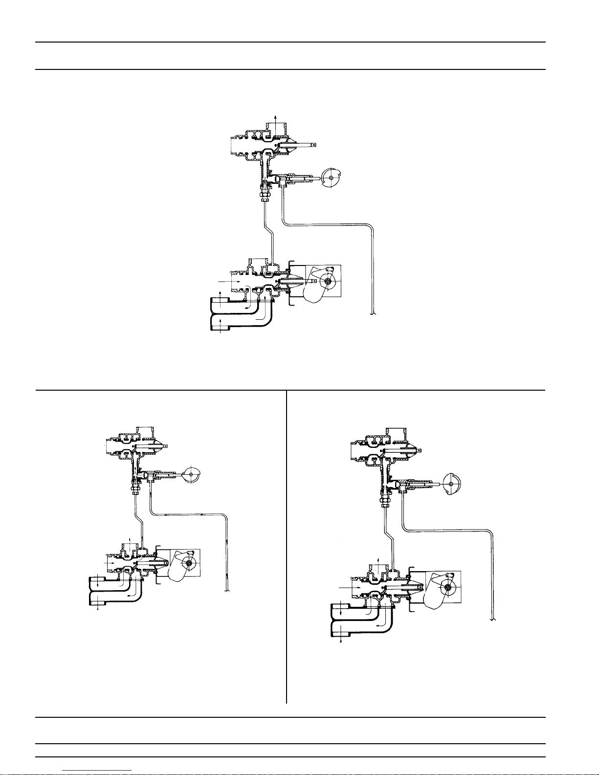
Water Conditioner Flow Diagrams
OUTLET
1 SERVICE POSITION
INLET
DRAIN
INLET
TOP OF TANK
BOTTOM
OF TANK
Hard water enters at valve inlet flows thru valve to the top of tank down thru mineral to the
bottom distributor. Conditioned water flows to the valve, around the piston and out the outlet.
2 BRINE AND SLOW RINSE POSITION
OUTLET
INLET
DRAIN
INLET
TOP OF TANK
TO BRINE
TANK
BOTTOM OF
TANK
Hard water enters at valve inlet flows thru the piston to the
injector nozzle and throat to draw brine from the brine tank
brine flows thru valve to the bottom of tank up thru
mineral to top of tank, around the piston and out the drain.
Flow thru injectors continues for slow rinse for remainder of
cycle. Hard water is also available at valve outlet
.
TO BRINE
TANK
3 BACKWASH POSITION
OUTLET
INLET
DRAIN
INLET
TOP OF TANK
TO BRINE
TANK
BOTTOM OF
TANK
Hard water enters at valve inlet flows thru piston to the
bottom of tank up thru mineral to top of tank, around the
piston and out the drain. Hard water is also available at valve
outlet.
Page 4
Printed in U.S.A.
MODEL 3150 UP-FLOW
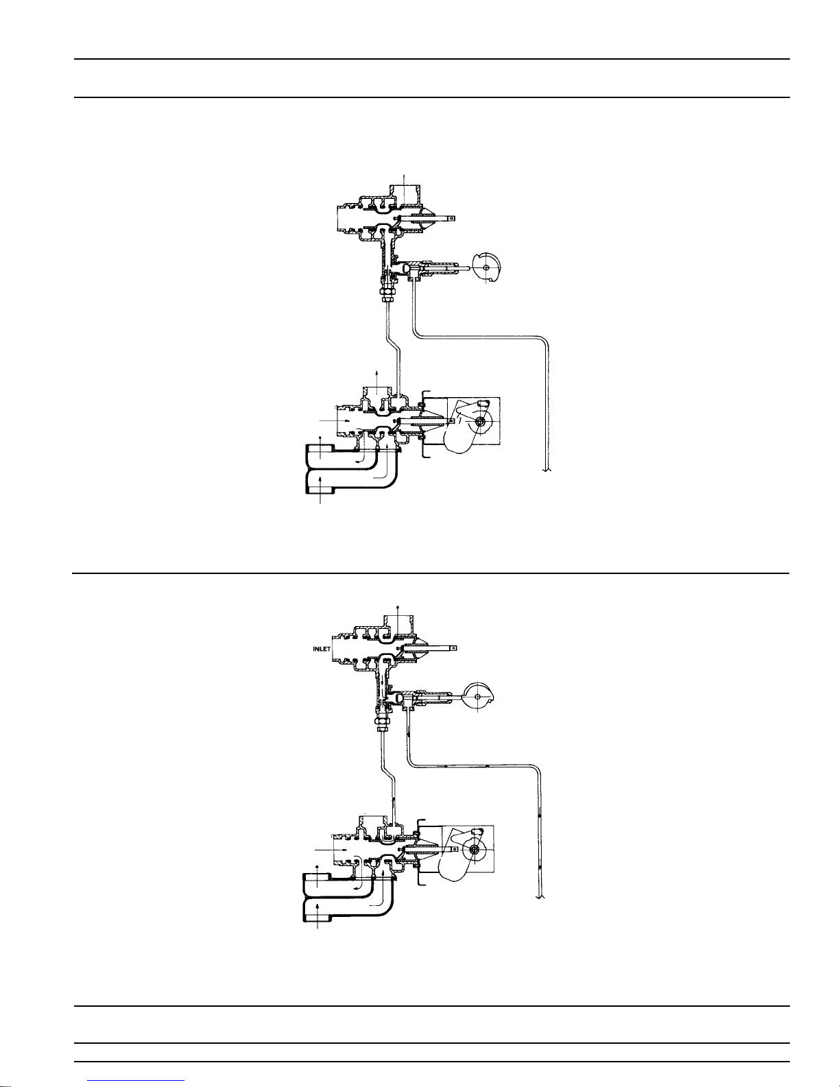
Water Conditioner Flow Diagrams (Cont’d.)
DRAIN
OUTLET
TO BRINE
TANK
4 RAPID RINSE POSITION
INLET
INLET
TOP OF TANK
BOTTOM OF
TANK
Hard water enters at valve inlet flows thru valve to the top bottom of tank down thru mineral to bottom
distributor back to top of tank, around the piston and out the drain. Hard water is also available at valve outlet.
5 BRINE TANK REFILL POSITION
INLET
DRAIN
INLET
TOP OF TANK
BOTTOM OF
TANK
Hard water enters at valve inlet flows thru valve to the top of tank down thru mineral to the bottom
distributor. Conditioned water flows up to valve outlet and thru the throat and nozzle to fill brine tank.
OUTLET
TO BRINE
TANK
Page 5
Printed in U.S.A.
MODEL 3150 UP-FLOW
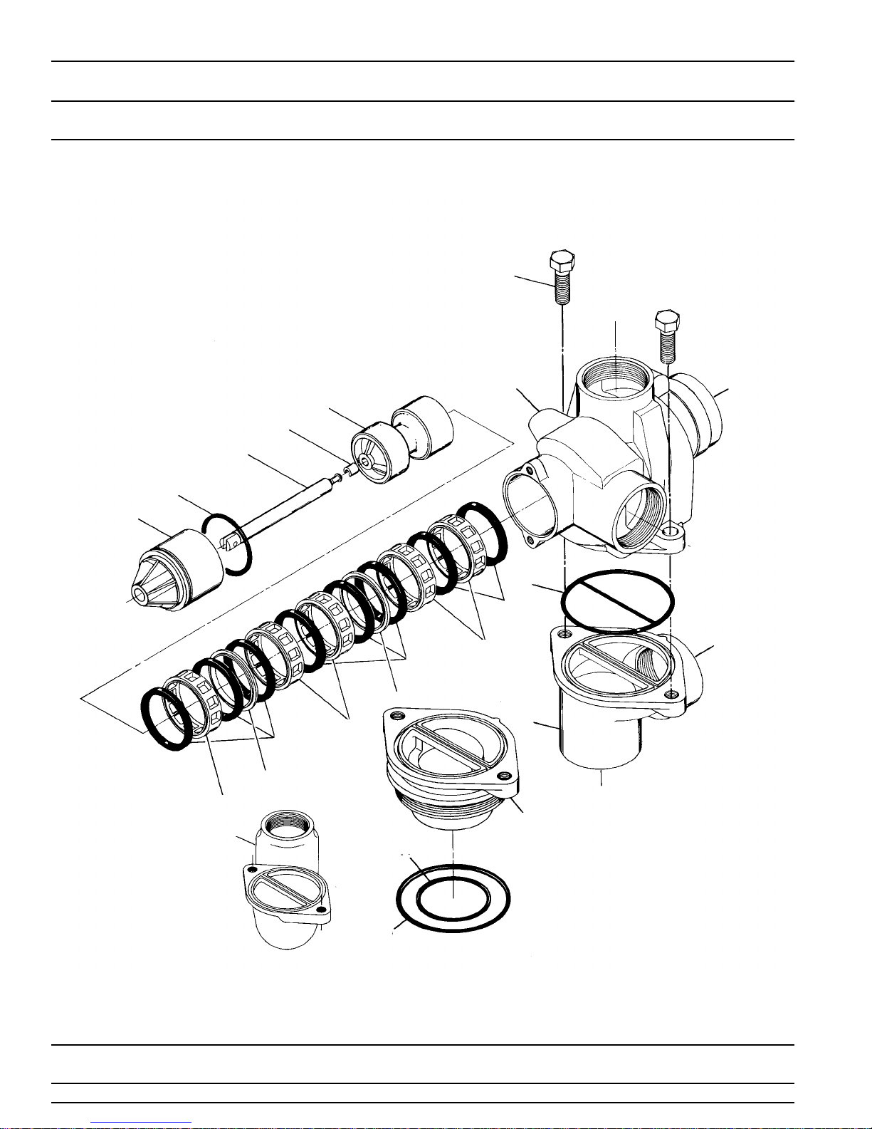
Control Valve
(see opposite page for parts list)
5
6
7
12
1
8
9
10
2
3
2
4
3
2
4
3
11B
14
11A
13
Page 6
15
Printed in U.S.A.

MODEL 3150 UP-FLOW
Control Valve
Parts List
Item No. Quantity Part No. Description
1. . . . . . . . . . . 1 . . . . . . . . . . . 15114 . . . . . . . . . . . . . . . Valve Body
15114-30NP . . . . . . . . . . Valve Body, Bsp, Nickel Plated
2. . . . . . . . . . . 8 . . . . . . . . . . . 11720 . . . . . . . . . . . . . . . Seal
3. . . . . . . . . . . 5 . . . . . . . . . . . 10369 . . . . . . . . . . . . . . . Spacer - Port
4. . . . . . . . . . . 2 . . . . . . . . . . . 10368 . . . . . . . . . . . . . . . Spacer
5. . . . . . . . . . . 1 . . . . . . . . . . . 16337 . . . . . . . . . . . . . . . Piston
6. . . . . . . . . . . 1 . . . . . . . . . . . 14818 . . . . . . . . . . . . . . . Clip - Piston Rod
7. . . . . . . . . . . 1 . . . . . . . . . . . 15125 . . . . . . . . . . . . . . . Piston Rod
8. . . . . . . . . . . 1 . . . . . . . . . . . 14922 . . . . . . . . . . . . . . . O-Ring - 035
9. . . . . . . . . . . 1 . . . . . . . . . . . 16398-21 . . . . . . . . . . . . . End Plug Assembly
10 . . . . . . . . . . 1 . . . . . . . . . . . 15112 . . . . . . . . . . . . . . . Seal
11A . . . . . . . . . 1 . . . . . . . . . . . 15115-01. . . . . . . . . . . . . Adapter - Side Mount 90˚
11B . . . . . . . . . 1 . . . . . . . . . . . 17407 . . . . . . . . . . . . . . . Adapter - Side Mount
12 . . . . . . . . . . 2 . . . . . . . . . . . 16042 . . . . . . . . . . . . . . . Screw - Hex Hd.
17122 . . . . . . . . . . . . . . . Metric
Options
13 . . . . . . . . . . 1 . . . . . . . . . . . 15117-01 . . . . . . . . . . . . . Adapter - Top Mount 4″ -8 Th’d.
14 . . . . . . . . . . 1 . . . . . . . . . . . 15247 . . . . . . . . . . . . . . . O-Ring - 229 (Dist.)
15 . . . . . . . . . . 1 . . . . . . . . . . . 13575 . . . . . . . . . . . . . . . O-Ring - 240 (Tank)
1 . . . . . . . . . . . 15210 . . . . . . . . . . . . . . . O-Ring (Park Tank)
1 . . . . . . . . . . . 19608-20. . . . . . . . . . . . . Disperser (Not shown)
Page 7
Printed in U.S.A.
MODEL 3150 UP-FLOW
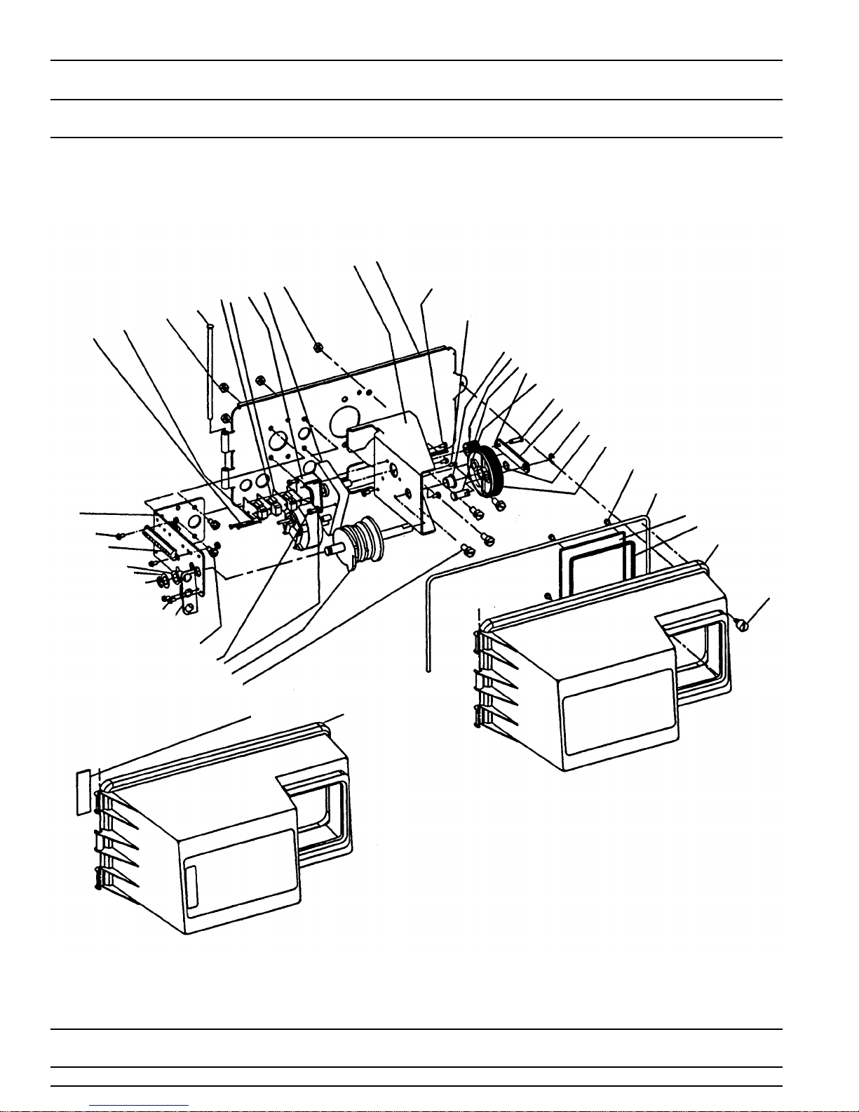
Control Drive Assembly
(see opposite page for parts list)
1
2
3
4
5
67
8
9
11
10
43
42
16
41
40
39
38
37
36
35
34
33
32
13
14
15
16
17
18
19
20
21
22
23
24
25
26
31
30
29
28A
27
28B
Page 8
Printed in U.S.A.

MODEL 3150 UP-FLOW
Control Drive Assembly
Parts List
Item No. Quantity Part No. Description
1 . . . . . . . . . . . 1 . . . . . . . . . . . . . . .19304-00 . . . . . . . . . . . . . . . . . . Back Plate -01, -02
2 . . . . . . . . . . . 1 . . . . . . . . . . . . . . .15120-01 . . . . . . . . . . . . . . . . . . Bracket - Motor Mounting
3 . . . . . . . . . . . 2 . . . . . . . . . . . . . . .16346 . . . . . . . . . . . . . . . . . . . . . Nut - 5/16-18
4 . . . . . . . . . . . 1 . . . . . . . . . . . . . . .16044 . . . . . . . . . . . . . . . . . . . . . Drive Motor -115 V. 60 Hz.
16500 . . . . . . . . . . . . . . . . . . . . . Drive Motor -220 V.50 Hz.
16501 . . . . . . . . . . . . . . . . . . . . . Drive Motor - 24 V. 60 Hz.
5 . . . . . . . . . . . 1 . . . . . . . . . . . . . . .17797 . . . . . . . . . . . . . . . . . . . . . Bracket - Switch Mounting
6 . . . . . . . . . . . 4 . . . . . . . . . . . . . . .10302 . . . . . . . . . . . . . . . . . . . . . Insulator - Switch
7 . . . . . . . . . . . 3 . . . . . . . . . . . . . . .10218 . . . . . . . . . . . . . . . . . . . . . Switch
8 . . . . . . . . . . . 1 . . . . . . . . . . . . . . .17845-03 . . . . . . . . . . . . . . . . . . Pin, Hinge
9 . . . . . . . . . . . 4 . . . . . . . . . . . . . . .11235 . . . . . . . . . . . . . . . . . . . . . Nut, 1/4-20
10 . . . . . . . . . . . 2 . . . . . . . . . . . . . . .13365 . . . . . . . . . . . . . . . . . . . . . Lockwasher
11 . . . . . . . . . . . 2 . . . . . . . . . . . . . . .12624 . . . . . . . . . . . . . . . . . . . . . Screw - Pan Hd.
13 . . . . . . . . . . . 1 . . . . . . . . . . . . . . .16053 . . . . . . . . . . . . . . . . . . . . .Bracket - Brine Side
14 . . . . . . . . . . . 2 . . . . . . . . . . . . . . .40133 . . . . . . . . . . . . . . . . . . . . . Screw - Round Hd.
15 . . . . . . . . . . . 1 . . . . . . . . . . . . . . .15226-❊ . . . . . . . . . . . . . . . . . . . Terminal Block
16 . . . . . . . . . . . 2 . . . . . . . . . . . . . . .16052 . . . . . . . . . . . . . . . . . . . . . Bushing
17 . . . . . . . . . . . 1 . . . . . . . . . . . . . . .16059 . . . . . . . . . . . . . . . . . . . . . Washer
18 . . . . . . . . . . . 1 . . . . . . . . . . . . . . .16051 . . . . . . . . . . . . . . . . . . . . . Retaining Ring - Bowed “E”
•19 . . . . . . . . . . . 2 . . . . . . . . . . . . . . .10300 . . . . . . . . . . . . . . . . . . . . . Screw - Hex Hd. Thread Cutting
•20 . . . . . . . . . . . 1 . . . . . . . . . . . . . . .19317 . . . . . . . . . . . . . . . . . . . . . Light Bracket
21 . . . . . . . . . . . 4 . . . . . . . . . . . . . . .10231 . . . . . . . . . . . . . . . . . . . . . Screw - Hex Hd.
22 . . . . . . . . . . . 2 . . . . . . . . . . . . . . .17567 . . . . . . . . . . . . . . . . . . . . . Screw - Hex Hd.
23 . . . . . . . . . . . 2 . . . . . . . . . . . . . . .12288 . . . . . . . . . . . . . . . . . . . . . Washer, Lock, #8 Internal
24 . . . . . . . . . . . 1 . . . . . . . . . . . . . . .16494-06 . . . . . . . . . . . . . . . . . . Cam Assembly - Service After RR
1 . . . . . . . . . . . . . . .16494-04 . . . . . . . . . . . . . . . . . . Cam Assembly - Service After Brine Refill
25 . . . . . . . . . . . 4 . . . . . . . . . . . . . . .11224 . . . . . . . . . . . . . . . . . . . . . Screw - Hex Hd.
•26 . . . . . . . . . . . 1 . . . . . . . . . . . . . . .19319 . . . . . . . . . . . . . . . . . . . . . Lamp Window
27 . . . . . . . . . . . 1 . . . . . . . . . . . . . . .18744 . . . . . . . . . . . . . . . . . . . . . Screw
28A . . . . . . . . . . . 1 . . . . . . . . . . . . . . .19277-020 . . . . . . . . . . . . . . . . . Cover, Black
•28B . . . . . . . . . . . 1 . . . . . . . . . . . . . . .19277-021 . . . . . . . . . . . . . . . . . Cover, Lamp Window
29 . . . . . . . . . . . 1 . . . . . . . . . . . . . . .18615-02 . . . . . . . . . . . . . . . . . . Seal, Window
30 . . . . . . . . . . . 1 . . . . . . . . . . . . . . .18745 . . . . . . . . . . . . . . . . . . . . . Window
31 . . . . . . . . . . . 1 . . . . . . . . . . . . . . .18716-03 . . . . . . . . . . . . . . . . . . Seal, Cover
32 . . . . . . . . . . . 4 . . . . . . . . . . . . . . .19203 . . . . . . . . . . . . . . . . . . . . . Screw
33 . . . . . . . . . . . 1 . . . . . . . . . . . . . . .16046 . . . . . . . . . . . . . . . . . . . . . Drive Gear
34 . . . . . . . . . . . 1 . . . . . . . . . . . . . . .16050 . . . . . . . . . . . . . . . . . . . . . Retaining Ring
35 . . . . . . . . . . . 1 . . . . . . . . . . . . . . .11774 . . . . . . . . . . . . . . . . . . . . . Retaining Ring “E”
36 . . . . . . . . . . . 1 . . . . . . . . . . . . . . .16047 . . . . . . . . . . . . . . . . . . . . . Drive Link
37 . . . . . . . . . . . 1 . . . . . . . . . . . . . . .11709 . . . . . . . . . . . . . . . . . . . . . Pin - Drive Link
38 . . . . . . . . . . . 1 . . . . . . . . . . . . . . .16048 . . . . . . . . . . . . . . . . . . . . . Bearing - Drive Link
39 . . . . . . . . . . . 1 . . . . . . . . . . . . . . .11898 . . . . . . . . . . . . . . . . . . . . . Clip
40 . . . . . . . . . . . 1 . . . . . . . . . . . . . . .16045 . . . . . . . . . . . . . . . . . . . . . Drive Pinion
41 . . . . . . . . . . . 1 . . . . . . . . . . . . . . .11381 . . . . . . . . . . . . . . . . . . . . . RolI Pin
42 . . . . . . . . . . . 1 . . . . . . . . . . . . . . .11080 . . . . . . . . . . . . . . . . . . . . . Screw - Flat Hd.
43 . . . . . . . . . . . 3 . . . . . . . . . . . . . . .10872 . . . . . . . . . . . . . . . . . . . . . Screw - Hex Hd.
44 . . . . . . . . . . . 1 . . . . . . . . . . . . . . . . . . . . . . . . . . . . . . . . . . . . . . . . . . Timer - (not shown) [3000, 3200, 3210, 3200E, 3200T]
45 . . . . . . . . . . . 1 . . . . . . . . . . . . . . .12287 . . . . . . . . . . . . . . . . . . . . . 7 ft. Power Cord (not shown)
12287-12 . . . . . . . . . . . . . . . . . . 12 ft. Power Cord
19713 . . . . . . . . . . . . . . . . . . . . . 230V US Power Cord
46 . . . . . . . . . . . 1 . . . . . . . . . . . . . . .17967 . . . . . . . . . . . . . . . . . . . . . Strain Relief (not shown)
47 . . . . . . . . . . . 1 . . . . . . . . . . . . . . .16430 . . . . . . . . . . . . . . . . . . . . . Harness (not shown)
48 . . . . . . . . . . . 1 . . . . . . . . . . . . . . .19691 . . . . . . . . . . . . . . . . . . . . . Hole Plug - 3/4 Dia. (not shown)
49 . . . . . . . . . . . 1 . . . . . . . . . . . . . . .19591 . . . . . . . . . . . . . . . . . . . . . Hole Plug - 7/8 Dia. (not shown)
50 . . . . . . . . . . . 1 . . . . . . . . . . . . . . .16427-04 . . . . . . . . . . . . . . . . . . Motor Lead Wire (not shown)
51 . . . . . . . . . . . 1 . . . . . . . . . . . . . . .16384 . . . . . . . . . . . . . . . . . . . . . Wire Harness (not shown)
52 . . . . . . . . . . . 1 . . . . . . . . . . . . . . .14924 . . . . . . . . . . . . . . . . . . . . . Strain Relief (not shown)
53 . . . . . . . . . . . 1 . . . . . . . . . . . . . . .15513 . . . . . . . . . . . . . . . . . . . . . Meter Cable (not shown)
54 . . . . . . . . . . . 2 . . . . . . . . . . . . . . .15250 . . . . . . . . . . . . . . . . . . . . . Label - Terminal Strip (not shown)
55 . . . . . . . . . . . 1 . . . . . . . . . . . . . . .16821 . . . . . . . . . . . . . . . . . . . . . Cable Guide Assembly (not shown)
❊ Specify number of terminals • Optional Parts for Lamp Package
Page 9
Printed in U.S.A.
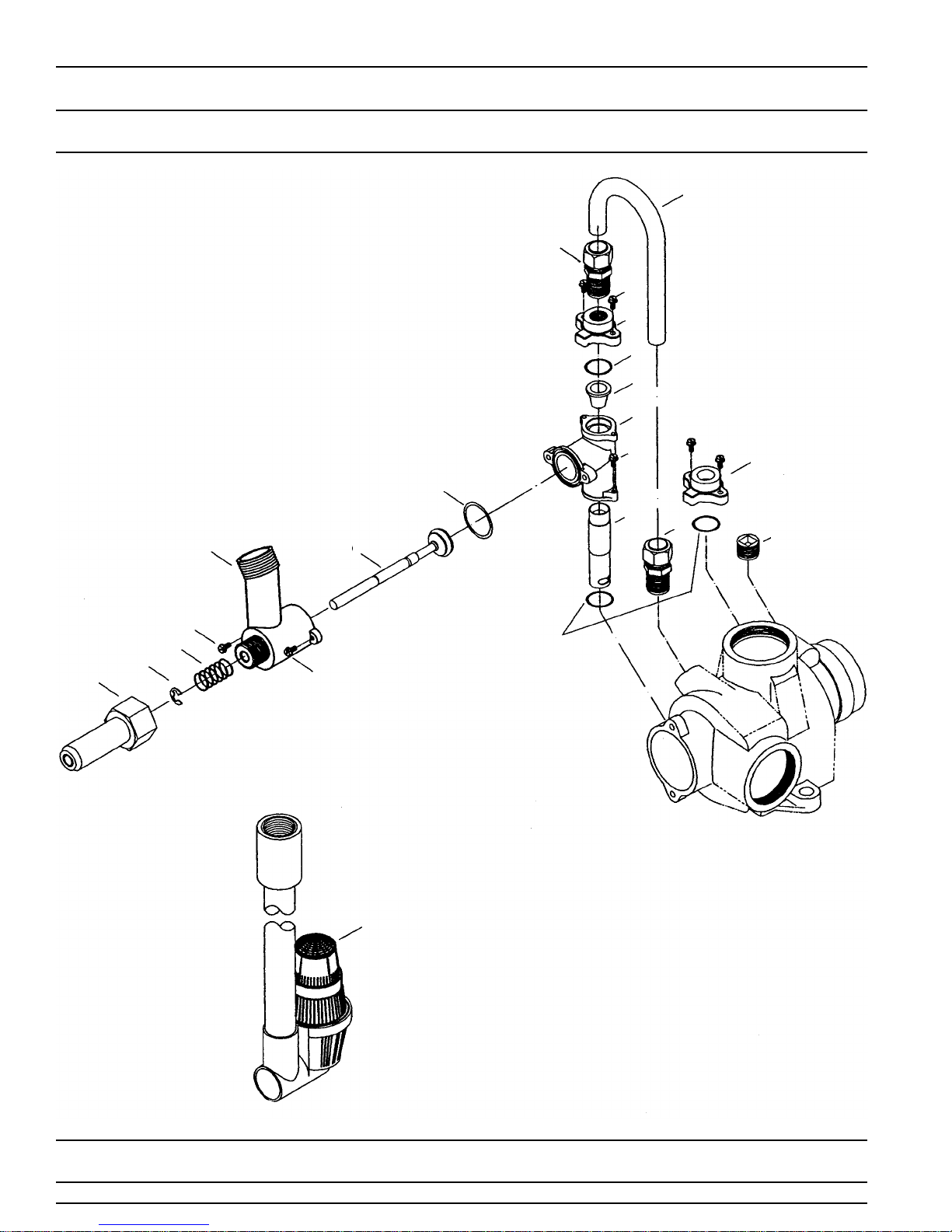
MODEL 3150 UP-FLOW
1800 Series Brine System Assembly
(see opposite page for parts list)
16
15
6
5
4
2
1
13
12
11
6
8
3
15
10
6
9
4
6
7
14
Page 10
17
Printed in U.S.A.

MODEL 3150 UP-FLOW
1800 Series Brine System Assembly
(see opposite page for parts list)
Item No. Quantity Part No. Description
11 . . . . . . . . . . . . . . . . . . . . . . . . . . . . . 16340-01 . . . . . . . . . . . . . . Injector Body
2. . . . . . . . . . . .1. . . . . . . . . . . . . . . . . 15128-❊ . . . . . . . . . . . . . . . Injector Nozzle
3. . . . . . . . . . . .1. . . . . . . . . . . . . . . . . 15127-❊ . . . . . . . . . . . . . . . Injector Throat
4. . . . . . . . . . . .3. . . . . . . . . . . . . . . . . 15246 . . . . . . . . . . . . . . . . . O-Ring -116
5. . . . . . . . . . . .1. . . . . . . . . . . . . . . . . 16341-01 . . . . . . . . . . . . . . Injector Cover
6. . . . . . . . . . . .6. . . . . . . . . . . . . . . . . 12473 . . . . . . . . . . . . . . . . . Screw - Hex Hd.
7. . . . . . . . . . . .1. . . . . . . . . . . . . . . . . 16341-02 . . . . . . . . . . . . . . Cover
8. . . . . . . . . . . .1. . . . . . . . . . . . . . . . . 16605 . . . . . . . . . . . . . . . . . Retainer Plate
9. . . . . . . . . . . .2. . . . . . . . . . . . . . . . . 13303 . . . . . . . . . . . . . . . . . O-Ring - 021
10 . . . . . . . . . . .1 . . . . . . . . . . . . . . . . . 16596 . . . . . . . . . . . . . . . . . Nut - Q.C.
11 . . . . . . . . . . .1 . . . . . . . . . . . . . . . . . 16203-01 . . . . . . . . . . . . . . Connector - Brine Valve
12 . . . . . . . . . . .1 . . . . . . . . . . . . . . . . . 16497 . . . . . . . . . . . . . . . . . Brine Stem Assembly
13 . . . . . . . . . . .1 . . . . . . . . . . . . . . . . . 15241 . . . . . . . . . . . . . . . . . Brine Valve Body
14 . . . . . . . . . . .1 . . . . . . . . . . . . . . . . . 11772 . . . . . . . . . . . . . . . . . Spring
15 . . . . . . . . . . .1 . . . . . . . . . . . . . . . . . 11774 . . . . . . . . . . . . . . . . . Retaining Ring
16 . . . . . . . . . . .1 . . . . . . . . . . . . . . . . . 16498-01 . . . . . . . . . . . . . . Stem Guide Assembly
17 . . . . . . . . . . .1 . . . . . . . . . . . . . . . . . 11912 . . . . . . . . . . . . . . . . . Fitting - Brine Line
18 . . . . . . . . . . .1 . . . . . . . . . . . . . . . . . 11183 . . . . . . . . . . . . . . . . . O-Ring - 017
19 . . . . . . . . . . .1 . . . . . . . . . . . . . . . . . 11180 . . . . . . . . . . . . . . . . . Screw - Round Hd.
20 . . . . . . . . . . .1 . . . . . . . . . . . . . . . . . 16387 . . . . . . . . . . . . . . . . . Pipe Plug - 1/2 NPT
21 . . . . . . . . . . .2 . . . . . . . . . . . . . . . . . 16388 . . . . . . . . . . . . . . . . . Tube Fitting - Straight
22 . . . . . . . . . . .1 . . . . . . . . . . . . . . . . . 16491 . . . . . . . . . . . . . . . . . Brine Tube - Not Shown
23 . . . . . . . . . . .1 . . . . . . . . . . . . . . . . . 60007 . . . . . . . . . . . . . . . . . Commercial Air Check
24 . . . . . . . . . . .1. . . . . . . . . . . . . . . . . . . . . . . . . . . . . . . . . . . . . . . . Flow Control - Specify Flow Rate-
❊ Specify size
Not - Shown
Option Without Brine Valve
1 . . . . . . . . . . . . . . . . 16620 . . . . . . . . . . . . . . . . . Fitting - Brine Tank
2 . . . . . . . . . . . . . . . . 10231 . . . . . . . . . . . . . . . . . Screw - Brine Side Bracket
2 . . . . . . . . . . . . . . . . 11235 . . . . . . . . . . . . . . . . . Nut - Brine Side Bracket
1 . . . . . . . . . . . . . . . . 13303 . . . . . . . . . . . . . . . . . O-Ring - 021
Delete: Items 9 thru 19
Injector Throat
Size Color
15127-05 . . . . . . . . . #5 . . . . . . . . . . . . . . . . . . . . Red
15127-06 . . . . . . . . . #6 . . . . . . . . . . . . . . . . . . . . White
15127-07 . . . . . . . . . #7 . . . . . . . . . . . . . . . . . . . . Blue
15127-08 . . . . . . . . . #8 . . . . . . . . . . . . . . . . . . . . Yellow
15127-09 . . . . . . . . . #9 . . . . . . . . . . . . . . . . . . . . Green
15127-10 . . . . . . . . . #10 . . . . . . . . . . . . . . . . . . . Black
Injector Nozzle
15128-05 . . . . . . . . . #5. . . . . . . . . . . . . . . . . . . . Red
15128-06 . . . . . . . . . #6. . . . . . . . . . . . . . . . . . . . White
15128-07 . . . . . . . . . #7 . . . . . . . . . . . . . . . . . . . . Blue
15128-08 . . . . . . . . . #8 . . . . . . . . . . . . . . . . . . . . Yellow
15128-09 . . . . . . . . . #9 . . . . . . . . . . . . . . . . . . . . Green
15128-10 . . . . . . . . . #10 . . . . . . . . . . . . . . . . . . . Black
Page 11
Printed in U.S.A.
 Loading...