

Fleck 2750 Service Manual
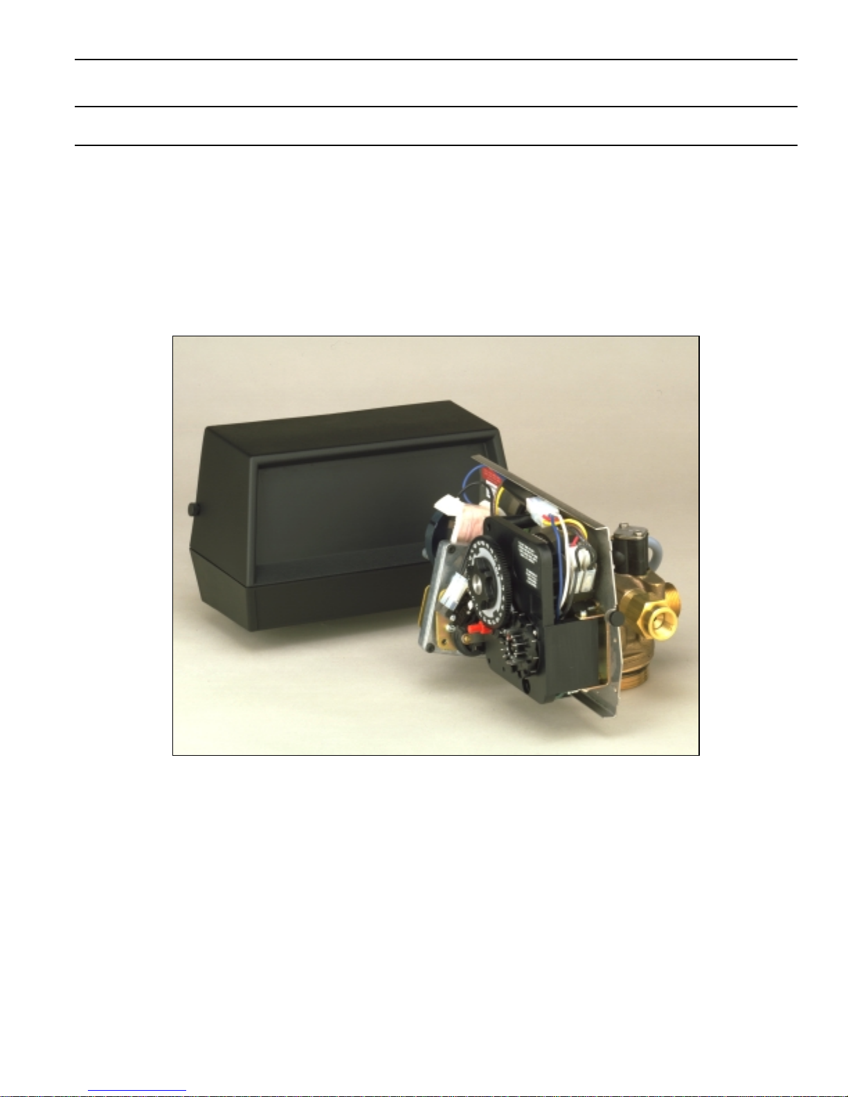
MODEL 2750 DOWNFLOW
CONTROL VALVE
Service Manual
IMPORTANT: Fill in pertinent information on page 2 for future reference.

MODEL 2750 DOWNFLOW
Job Specification Sheet
* JOB NO._________________________________________________________
* MODEL NO.______________________________________________________
* WATER TEST_____________________________________________________
* CAPACITY PER UNIT ___________________________
* MINERAL TANK SIZE DIA. ______HEIGHT_________
* BRINE TANK SIZE & SALT SETTING PER REGENERATION:
_________________________________________________________________
* 2750 CONTROL VALVE SPECIFICATIONS
1) Type of Timer (see pages 16,17, & 18)
A) 7 day or 12 day
B) *310 to 5,270 gallon meter or
*1,550 to 26,350 gallon meter
* Other_______________________________________________________
C) Meter Wiring Package
1) System #4 - 1 tank; 1 meter; immediate or delayed regeneration
2) System #5 - 2 tanks; 2 meters; interlock
3) System #6 - 2 tanks; 1 meter; series regeneration
4) System #7 - 2 tanks; 1 meter; alternator
2) Timer Program Settings (see pages 18 and 19)
A) Backwash _______________________ min.
B) Brine & Slow Rinse ________________min.
C) Rapid Rinse _____________________min.
D) Brine Tank Refill___________________ min.
3) Drain Line Flow Controller ______________gpm
4) Brine Line Flow Controller ______________ gpm
5) Injector Size # _______________________
6) Service Valve Operation Units (SVO)
Size of Service Valve _______________________________________________ .
Page 2
Printed in U.S.A.

MODEL 2750 DOWNFLOW
General Commercial Pre-Installation Check List
WATER PRESSURE: A minimum of 25 pounds of water pressure is required for regeneration valve to operate
effectively.
ELECTRICAL FACILITIES: A continuous 110 volt, 60 Hertz current supply is required. Make certain the current supply
is always hot and cannot be turned off with another switch. (Other voltages available.)
EXISTING PLUMBING: Condition of existing plumbing should be free from lime and iron buildup. Piping that is built up
heavily with lime and/or iron should be replaced. If piping is clogged with iron, a separate iron filter unit should be
installed ahead of the water softener.
LOCATION OF SOFTENER AND DRAIN: The softener should be located close to a drain.
BY-PASS VALVES: Always provide for the installation of a by-pass valve.
CAUTION: Water pressure is not to exceed 120 p.s.i., water temperature is not to exceed 100˚ F, and the unit cannot
be subjected to freezing conditions.
INSTALLATION INSTRUCTIONS
1. Place the softener tank where you want to install the unit making sure the unit is level and on a firm base.
(Maximum 4 feet apart for twin units.)
2. All plumbing should be done in accordance with local plumbing codes. The pipe size for the drain line should be the
same size as the drain line flow control female connection. Water meters are to be installed on soft water outlets.
Twin units with (1) one meter shall be installed on common soft water outlet of units.
3. Solder joints near the drain must be done prior to connecting the Drain Line Flow Control fitting. Leave at least 6″
between the DLFC and solder joints when soldering when the pipes are connected on the DLFC. Failure to do this
could cause interior damage to the DLFC.
4. Teflon tape is the only sealant to be used on the drain fitting. The drain from twin units may be run through a
common line.
5. Make sure that the floor is clean beneath the salt storage tank and that it is level.
6. Place approximately 1″ of water above the grid plate (if used) in your salt tank. Salt may be placed in the unit at this
time.
7. On units with a by-pass, place in by-pass position. Turn on the main water supply. Open a cold soft water tap
nearby and let run a few minutes or until the system is free from foreign material (usually solder) that may have
resulted from the installation.
8. Place the by-pass in service position.
9. Manually index the softener control into “service” position and let water flow into the mineral tank. When water flow
stops, open a cold water tap nearby and let run until air pressure is relieved.
10. Electrical: All electrical connections must be connected according to codes. Use electrical conduit if applicable.
Remote meter systems and Twin meter system wiring diagrams are on page 25. Plug into power supply.
Page 3
Printed in U.S.A.
MODEL 2750 DOWNFLOW
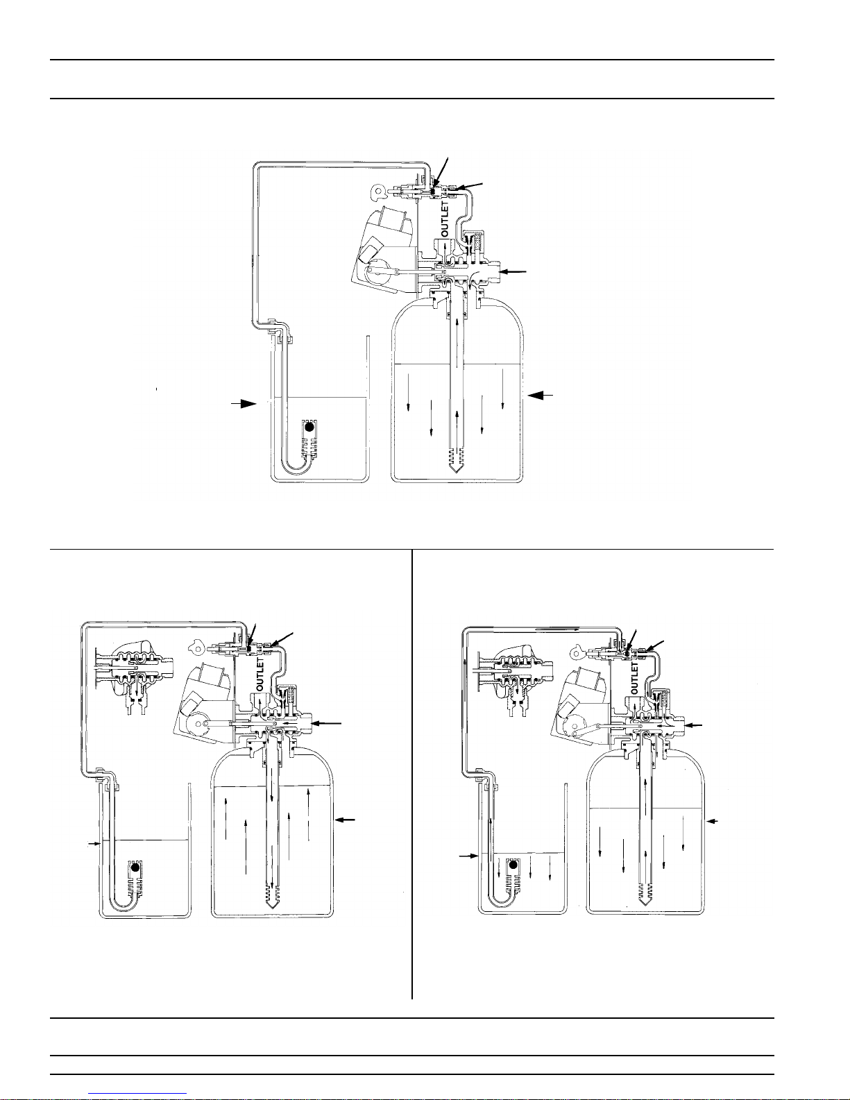
Water Conditioners Flow Diagrams
1 SERVICE POSITION
BRINE VALVE
FLOW CONTROL
INLET
BRINE TANK
Hard water enters unit at valve inlet and flows down thru the mineral in the mineral tank.
Conditioned water enters center tube thru the bottom distributor
center tube
around the piston and out the top outlet of the valve.
then flows up thru the
MINERAL TANK
2 BACKWASH POSITION 3 BRINE POSITION
BRINE VALVE
FLOW CONTROL
INLET
BRINE VALVE
FLOW
CONTROL
INLET
BRINE
TANK
Hard water enters unit at valve inlet flows thru piston down
center tube
around the piston and out the drain line.
thru bottom distributor and up thru the mineral
Page 4
MINERAL
TANK
Printed in U.S.A.
MINERAL
TANK
BRINE
TANK
Hard water enters unit at valve inlet
housing and down thru nozzle and orifice to draw brine from the
brine tank
tube thru bottom distributor and out thru the drain line.
brine flows down thru mineral and enters the center
flows up into injector
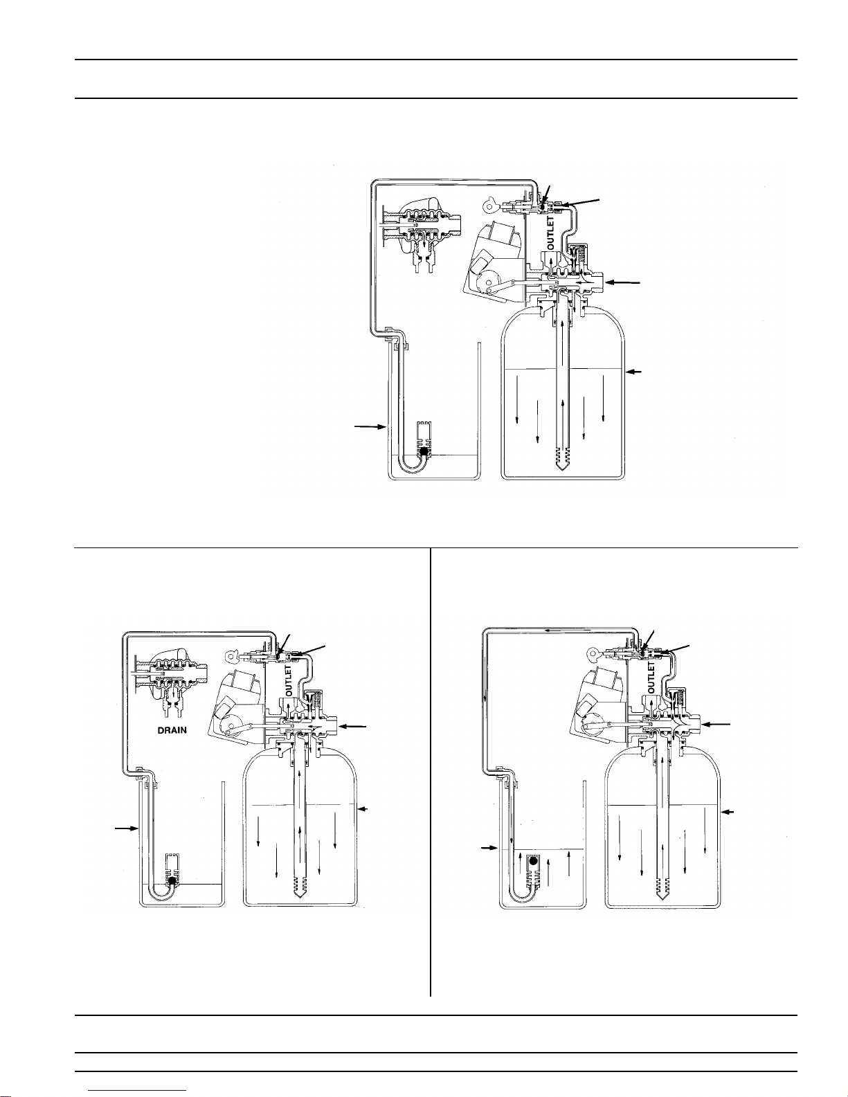
MODEL 2750 DOWNFLOW
Water Conditioners Flow Diagrams (Cont’d.)
4 SLOW RINSE POSITION
BRINE TANK
Hard water enters unit at valve inlet flows up into injector housing and down thru nozzle
and orifice
distributor
around the piston down thru mineral enters center tube thru bottom
flows up thru center tube around piston and out thru drain line.
BRINE VALVE
FLOW CONTROL
INLET
MINERAL TANK
5 RAPID RINSE 6 BRINE TANK FILL POSITION
BRINE TANK
FLOW
CONTROL
INLET
MINERAL
BRINE
TANK
Hard water flows directly from inlet down thru mineral into center
tube bottom distributor and up thru center tube
and out thru the drain line.
around piston
TANK
BRINE
TANK
Hard water enters unit at valve inlet
housing
thru the brine valve to fill the brine tank.
flows up thru the injector
BRINE TANK
FLOW
CONTROL
INLET
MINERAL
TANK
Page 5
Printed in U.S.A.
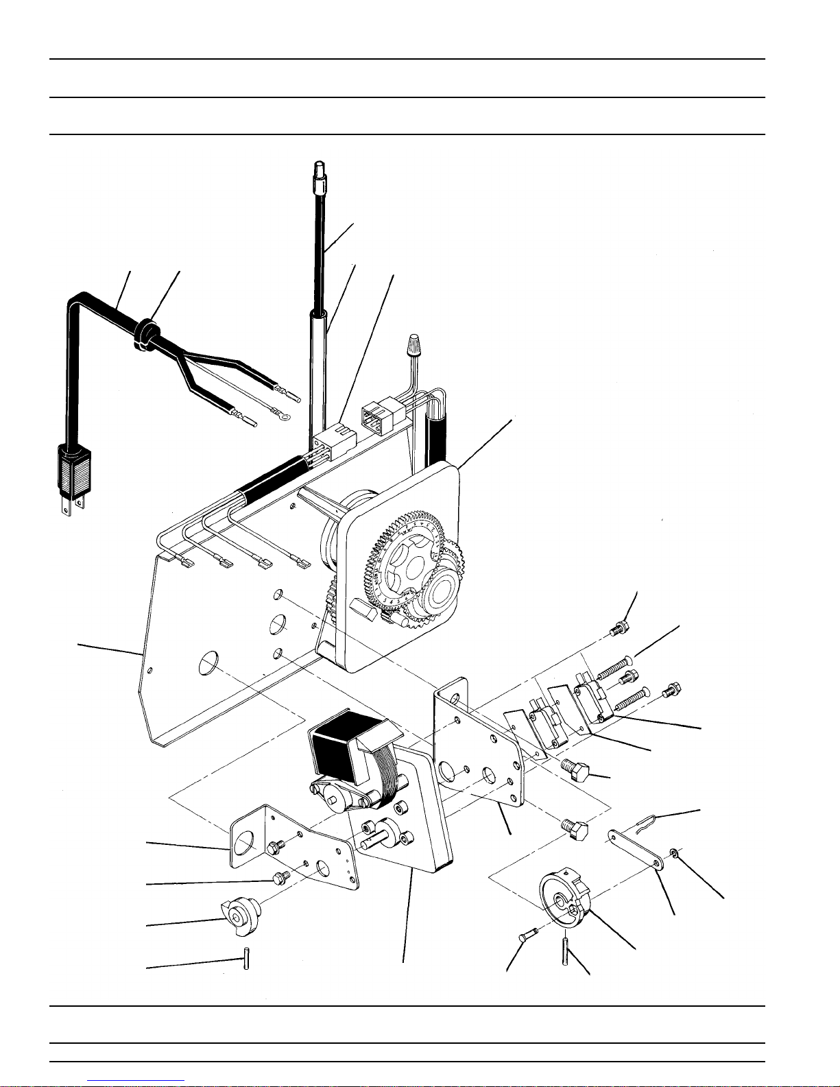
MODEL 2750 DOWNFLOW
Control Drive Assembly
(see opposite page for parts list)
25
3
1
4
24
5
2
7
20
22
7
23
18
Page 6
21
Printed in U.S.A.
19
13
12
11
14
10
15
16
17
18

MODEL 2750 DOWNFLOW
Control Drive Assembly
Parts List
Item No. Quantity Part No. Description
1 . . . . . . . . . 1 . . . . . . . . . . 14884 . . . . . . . . . . . . . Back Plate
1 . . . . . . . . . . 11209 . . . . . . . . . . . . . Back Plate - Slant Front (not shown)
1 . . . . . . . . . . 15156 . . . . . . . . . . . . . Back Plate - SVO (not shown)
2 . . . . . . . . . 1 . . . . . . . . . . . . . . . . . . . . . . . . . . . . . Timer - 3200 7 Day
3 . . . . . . . . . 1 . . . . . . . . . . 11838 . . . . . . . . . . . . . Power Cord
4 . . . . . . . . . 1 . . . . . . . . . . 13547 . . . . . . . . . . . . . Strain Relief
5 . . . . . . . . . 1 . . . . . . . . . . 11667 . . . . . . . . . . . . . Wire Harness
7 . . . . . . . . . 5 . . . . . . . . . . 10872 . . . . . . . . . . . . . Screw - Motor Mounting
8 . . . . . . . . . . . . . . . . . . . . . . . . . . . . . . . . . . . . . . . Not Assigned
9 . . . . . . . . . . . . . . . . . . . . . . . . . . . . . . . . . . . . . . . Not Assigned
10. . . . . . . . . 1 . . . . . . . . . . 10774 . . . . . . . . . . . . . Bracket - Motor Mounting
11. . . . . . . . . 2 . . . . . . . . . . 10231 . . . . . . . . . . . . . Screw - Drive Mounting
12. . . . . . . . . 2 . . . . . . . . . . 10302 . . . . . . . . . . . . . Insulator
13. . . . . . . . . 2 . . . . . . . . . . 10218 . . . . . . . . . . . . . Switch
14. . . . . . . . . 1 . . . . . . . . . . 10909 . . . . . . . . . . . . . Connecting Link Pin
15. . . . . . . . . 3 . . . . . . . . . . 10250 . . . . . . . . . . . . . Retaining Ring
16. . . . . . . . . 1 . . . . . . . . . . 10621 . . . . . . . . . . . . . Connecting Link
17. . . . . . . . . 1 . . . . . . . . . . 12102 . . . . . . . . . . . . . Drive Cam - RR
1 . . . . . . . . . . 12576 . . . . . . . . . . . . . Drive Cam - STF
18. . . . . . . . . 2 . . . . . . . . . . 10338 . . . . . . . . . . . . . Roll Pin
19. . . . . . . . . 1 . . . . . . . . . . 13366 . . . . . . . . . . . . . Drive Bearing
20. . . . . . . . . 2 . . . . . . . . . . 14923 . . . . . . . . . . . . . Screw - Switch Mounting
21. . . . . . . . . 1 . . . . . . . . . . 10769 . . . . . . . . . . . . . Motor
22. . . . . . . . . 1 . . . . . . . . . . 11826 . . . . . . . . . . . . . Bracket - Brine Valve Side
23. . . . . . . . . 1 . . . . . . . . . . 12777 . . . . . . . . . . . . . Brine Valve Cam - STF
1 . . . . . . . . . . 10815 . . . . . . . . . . . . . Brine Valve Cam - RR (not shown)
1 . . . . . . . . . . 12472 . . . . . . . . . . . . . Brine Valve Cam - SVO (not shown) - TRI
24. . . . . . . . . 1 . . . . . . . . . . 15441 . . . . . . . . . . . . . Meter Cable Guide Assembly
25. . . . . . . . . 1 . . . . . . . . . . 15513 . . . . . . . . . . . . . Meter Cable Assembly
26. . . . . . . . . 2 . . . . . . . . . . 10300 . . . . . . . . . . . . . Screw - Timer Mounting (not shown)
27. . . . . . . . . 2 . . . . . . . . . . 15742 . . . . . . . . . . . . . Screw (not shown)
28. . . . . . . . . 2 . . . . . . . . . . 15833 . . . . . . . . . . . . . Spacer, Cover (not shown)
29. . . . . . . . . 1 . . . . . . . . . . 19291-020. . . . . . . . . . Cover, 1 Piece, Black (not shown)
30. . . . . . . . . 2 . . . . . . . . . . 19367 . . . . . . . . . . . . . Screw, Cover (not shown)
- 3200 12 Day
- 3210 Meter
Page 7
Printed in U.S.A.

MODEL 2750 DOWNFLOW
Control Valve with 1700 Injector
(see opposite page for parts list)
16
15
14
1213
28
11
24
10
9
17
18
1
30
2
29
15
14
27
26
25
19
20
21
22
19
Page 8
3
4
5
6
7
8
Printed in U.S.A.

MODEL 2750 DOWNFLOW
Control Valve
Parts List
Item No. Quantity Part No. Description
1 . . . . . . . . . 1 . . . . . . . . . . 14749 . . . . . . . . . . . . . Valve Body
2 . . . . . . . . . 6 . . . . . . . . . . 10545 . . . . . . . . . . . . . Seal
3 . . . . . . . . . 5 . . . . . . . . . . 11451 . . . . . . . . . . . . . Spacer
16589 . . . . . . . . . . . . . Spacer, Hot Water
4 . . . . . . . . . 1 . . . . . . . . . . 14451 . . . . . . . . . . . . . Piston
5 . . . . . . . . . 1 . . . . . . . . . . 14452 . . . . . . . . . . . . . Piston Rod
6 . . . . . . . . . 1 . . . . . . . . . . 10234 . . . . . . . . . . . . . O-Ring - End Plug
7 . . . . . . . . . 1 . . . . . . . . . . 10209 . . . . . . . . . . . . . Quad Ring - Piston Rod
8 . . . . . . . . . 1 . . . . . . . . . . 10598 . . . . . . . . . . . . . End Plug Assembly
10598-01 . . . . . . . . . . End Plug Assembly, Hot Water
9 . . . . . . . . . 1 . . . . . . . . . . 14805 . . . . . . . . . . . . . Injector Body Gasket
10. . . . . . . . . 1 . . . . . . . . . . 14802 . . . . . . . . . . . . . Injector Throat
11. . . . . . . . . 1 . . . . . . . . . . 17777 . . . . . . . . . . . . . Injector Body
12. . . . . . . . . 1 . . . . . . . . . . 14801 . . . . . . . . . . . . . Injector Nozzle
13. . . . . . . . . 1 . . . . . . . . . . 14803 . . . . . . . . . . . . . Injector Screen
14. . . . . . . . . 1 . . . . . . . . . . 10229 . . . . . . . . . . . . . Injector Cover Gasket
15. . . . . . . . . 1 . . . . . . . . . . 11893 . . . . . . . . . . . . . Injector Cover
10228 . . . . . . . . . . . . . Injector Cover, Hot Water
16. . . . . . . . . 2 . . . . . . . . . . 14804 . . . . . . . . . . . . . Screw - Injector Body
17. . . . . . . . . 1 . . . . . . . . . . . . . . . . . . . . . . . . . . . . . Washer - Flow Control (specify size)
18. . . . . . . . . 1 . . . . . . . . . . 15177 . . . . . . . . . . . . . Flow Control Housing
19. . . . . . . . . 2 . . . . . . . . . . 11710 . . . . . . . . . . . . . O-Ring Base
20. . . . . . . . . 1 . . . . . . . . . . 11208 . . . . . . . . . . . . . O-Ring Base
21. . . . . . . . . 1 . . . . . . . . . . 12461 . . . . . . . . . . . . . Adapter Base 2-1/2-8 Thd
22. . . . . . . . . 1 . . . . . . . . . . 10381 . . . . . . . . . . . . . O-Ring - Top of Tank
24. . . . . . . . . 2 . . . . . . . . . . 11224 . . . . . . . . . . . . . Screw - Valve Mounting
25. . . . . . . . . 1 . . . . . . . . . . 17776 . . . . . . . . . . . . . Injector Body
26. . . . . . . . . 1 . . . . . . . . . . 10914 . . . . . . . . . . . . . Injector Throat
27. . . . . . . . . 1 . . . . . . . . . . 10913 . . . . . . . . . . . . . Injector Nozzle
28. . . . . . . . . 1 . . . . . . . . . . 10227 . . . . . . . . . . . . . Injector Screen
29. . . . . . . . . 2 . . . . . . . . . . 10692 . . . . . . . . . . . . . Screw - Injector Body
30. . . . . . . . . 1 . . . . . . . . . . 10757 . . . . . . . . . . . . . End Spacer
31. . . . . . . . . 1 . . . . . . . . . . 16221 . . . . . . . . . . . . . Air Disperser - 1600 Injector (not shown)
10757B. . . . . . . . . . . . End Spacer, Hot Water
Page 9
Printed in U.S.A.
MODEL 2750 DOWNFLOW
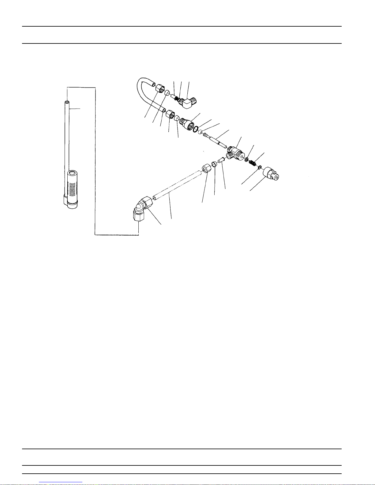
1600 Series Brine System Assembly
321
7
4
5
6
4
5
9
8
20
19
18
17
16
15
14
10
3
5
4
11
PARTS LIST
Item No. Quantity Part No. Description
1 . . . . . . . . . . . 1. . . . . . . . . . . . 10328. . . . . . . . . . . . . . . . 90° Elbow - 1/4″ Pipe Thd. to 3/8″ Tube
2 . . . . . . . . . . . 1. . . . . . . . . . . . 12767. . . . . . . . . . . . . . . . Brine Line Screen
3 . . . . . . . . . . . 2. . . . . . . . . . . . 10332. . . . . . . . . . . . . . . . Insert Sleeve (3/8″ Tube)
4 . . . . . . . . . . . 3. . . . . . . . . . . . 10329. . . . . . . . . . . . . . . . Fitting Nut (3/8″ Tube)
5 . . . . . . . . . . . 3. . . . . . . . . . . . 10330. . . . . . . . . . . . . . . . Derlin Sleeve (3/8″ Tube)
6 . . . . . . . . . . . 1. . . . . . . . . . . . 15221. . . . . . . . . . . . . . . . Brine Valve Tube
7 . . . . . . . . . . . 1. . . . . . . . . . . . 60002. . . . . . . . . . . . . . . . #500 Air Check Assembly
60003. . . . . . . . . . . . . . . .#500 Air Check Assembly, Hot Water
8 . . . . . . . . . . . 1. . . . . . . . . . . . 12794. . . . . . . . . . . . . . . . 90˚ Elbow - 3/8″ Tube to 3/8″ Tube
9 . . . . . . . . . . . 1. . . . . . . . . . . . Not Supplied . . . . . . . . . . Brine Line Tube (3/8″ Flexible Tube)
10. . . . . . . . . . . 1. . . . . . . . . . . .10250. . . . . . . . . . . . . . . .Retaining Ring
11. . . . . . . . . . . 1. . . . . . . . . . . .11749. . . . . . . . . . . . . . . .Stem Guide
12. . . . . . . . . . . . . . . . . . . . . . . . . . . . . . . . . . . . . . . . . . . . . Not Assigned
13. . . . . . . . . . . . . . . . . . . . . . . . . . . . . . . . . . . . . . . . . . . . . Not Assigned
14. . . . . . . . . . . 1. . . . . . . . . . . .10249. . . . . . . . . . . . . . . .Brine Valve Spring
15. . . . . . . . . . . 1. . . . . . . . . . . .12550. . . . . . . . . . . . . . . .Quad Ring
16. . . . . . . . . . . 1. . . . . . . . . . . .12748. . . . . . . . . . . . . . . .Brine Valve Body
17. . . . . . . . . . . 1. . . . . . . . . . . .12552. . . . . . . . . . . . . . . .Brine Valve Stem
18. . . . . . . . . . . 1. . . . . . . . . . . .12626. . . . . . . . . . . . . . . .Brine Valve Seat
19. . . . . . . . . . . 1. . . . . . . . . . . .11982. . . . . . . . . . . . . . . .O-Ring
20. . . . . . . . . . . 1. . . . . . . . . . . .60020-25 . . . . . . . . . . . . . BLFC .25 GPM
60020-50 . . . . . . . . . . . . . BLFC .50 GPM
60020-100 . . . . . . . . . . . . BLFC 1.0 GPM
Page 10
Printed in U.S.A.
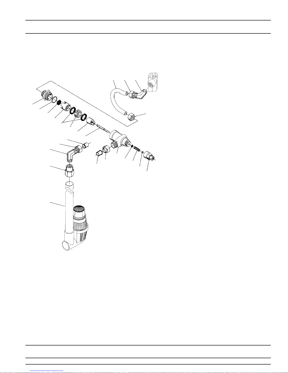
MODEL 2750
1700 Series Brine System
17 15 16
1
2
3
4
5
6
202114
16
18
7
8
20
14
21
15
9
10
11
12
13
19
PARTS LIST
Item No. Quantity Part No. Description
1. . . . . . . . 1 . . . . . . 14792 . . . . . . . End Plug
2. . . . . . . . 1 . . . . . . 13201 . . . . . . . O-Ring - End Plug
3. . . . . . . . 1 . . . . . . . . . . . . . . . . . . . Washer Flow Control (specify size)
4. . . . . . . . 1 . . . . . . 14785 . . . . . . . Flow Control Retainer
5. . . . . . . . 2 . . . . . . 14811 . . . . . . . Piston Seals
6. . . . . . . . 1 . . . . . . 14798 . . . . . . . Spacer
7. . . . . . . . 1 . . . . . . 14795 . . . . . . . Brine Valve Piston
8. . . . . . . . 1 . . . . . . 14797 . . . . . . . Brine Valve Stem
9. . . . . . . . 1 . . . . . . .14790 . . . . . . . Brine Valve Body
10. . . . . . . . 1 . . . . . . .12550 . . . . . . . Quad Ring - Brine Stem
11. . . . . . . . 1 . . . . . . .15310 . . . . . . . Spring - Brine Valve
12. . . . . . . . 1 . . . . . . .10250 . . . . . . . Retaining Ring
13. . . . . . . . 1 . . . . . . .15517 . . . . . . . Stem Guide
14. . . . . . . . 2 . . . . . . .15415 . . . . . . . Insert
15. . . . . . . . 2 . . . . . . .15414 . . . . . . . Nut & Sleeve
16. . . . . . . . 2 . . . . . . .15413 . . . . . . . Elbow
17. . . . . . . . 1 . . . . . . .15416 . . . . . . . Brine Tube
18. . . . . . . . 1 . . . . . . .16977 . . . . . . . Reducer Coupling, 1/2″ NPT to 1/8″ NPT
19. . . . . . . . 1 . . . . . . .60009 . . . . . . . #900 Air Check Assembly
60009-01 . . . . #900 Air Check Assembly, Hot Water
20. . . . . . . . 2 . . . . . . .16123 . . . . . . . Nut
21. . . . . . . . 2 . . . . . . .16124 . . . . . . . Sleeve
Page 11
Printed in U.S.A.
 Loading...