

Page 1
Green and yellow:
EARTH
Blue:
NEUTRAL
Red:
LIVE
Valiant
This product is only suitable for well insulated spaces or occasional use
Installation & Precautions
Carefully remove the fire from the packing, checking that neither the heater nor the power cable has been damaged during transport. Do not
operate the fire if either is damaged. Please bear in mind the weight of the fire before removal from the packaging and installation. Consider if
help is required. Any alteration to the power cable should only be done by a qualified electrician and to the Flamerite Fires guidelines stated
below. Your fire is guaranteed for one year from the date of purchase. In the unlikely event of a breakdown you have access to our customer
services team, simply call 01543 251122 during office hours, 9am – 5pm or e-mail on [email protected]
that is packed at the side of the fire.
INSTALLATION
Where a chimney is not blocked off completely it will cause the heater to cut out during use. ONLY if installing into a chimney and you are not
sure that you have cut off the draw 100% we recommend covering the slots in the rear and at either side.
Automatic safety cut out: The heater is fitted with an automatic cut out to prevent any damage due to overheating. The element will continually
and automatically cut out if the airflow is obstructed. Never cover the air outlets. To reset, switch the fire off, disconnect from the mains supply,
remove the cause of the overheating, check the micro switches and allow to cool for a suitable period then switch the fire back on. Caution: In
order to avoid a hazard due to inadvertent resetting of the thermal cut out, the appliance must not be supplied through an external switching
device, such as a timer, or connected to circuit regularly switched on and off by a utility.
Electrical connections: Your appliance comes fitted with a plug that incorporates a 13A fuse. The replacement fuses must be 13A and ASTA
approved. If the fuse cover is lost the plug must not be used until a replacement cover, of the same colour, is obtained from an electrical retailer.
The appliance is fitted with a moulded plug if it is necessary cut off the plug, for any reason, it must be discarded immediately with the fuse
removed. Under no circumstances should any attempt be made to reuse the plug, do not insert into any 13A socket as this could cause a hazard. If
the mains cable is damaged it must be replaced by the manufacturer or an authorised technical service centre.
WARNING THIS APPLIANCE MUST BE EARTHED
IMPORTANT
The wires in the mains lead are coloured in accordance with the following code.
The accessories are found in a box
As the colours of the wires in the mains lead of this appliance may not correspond with the colour markings in your plug proceed as follows: -
• The wire which is coloured green and yellow must be connected to the terminal in the plug which is marked with the letter E, or
coloured green or coloured green and yellow, or marked with the earth symbol
• The wire which is coloured blue must be connected to the terminal in the plug which is marked with the letter N, or coloured
black.
• The wire which is coloured brown must be connected to the terminal in the plug which is marked with the letter L, or coloured
red.
Insert the plug tightly into its IEC connector underneath the fire if not already done so. If the removal of the plug is absolutely necessary for
installation, cut off in an area within 100mm only of the plug itself. Any further will affect your warranty.
Page 1 of 3
Page 2
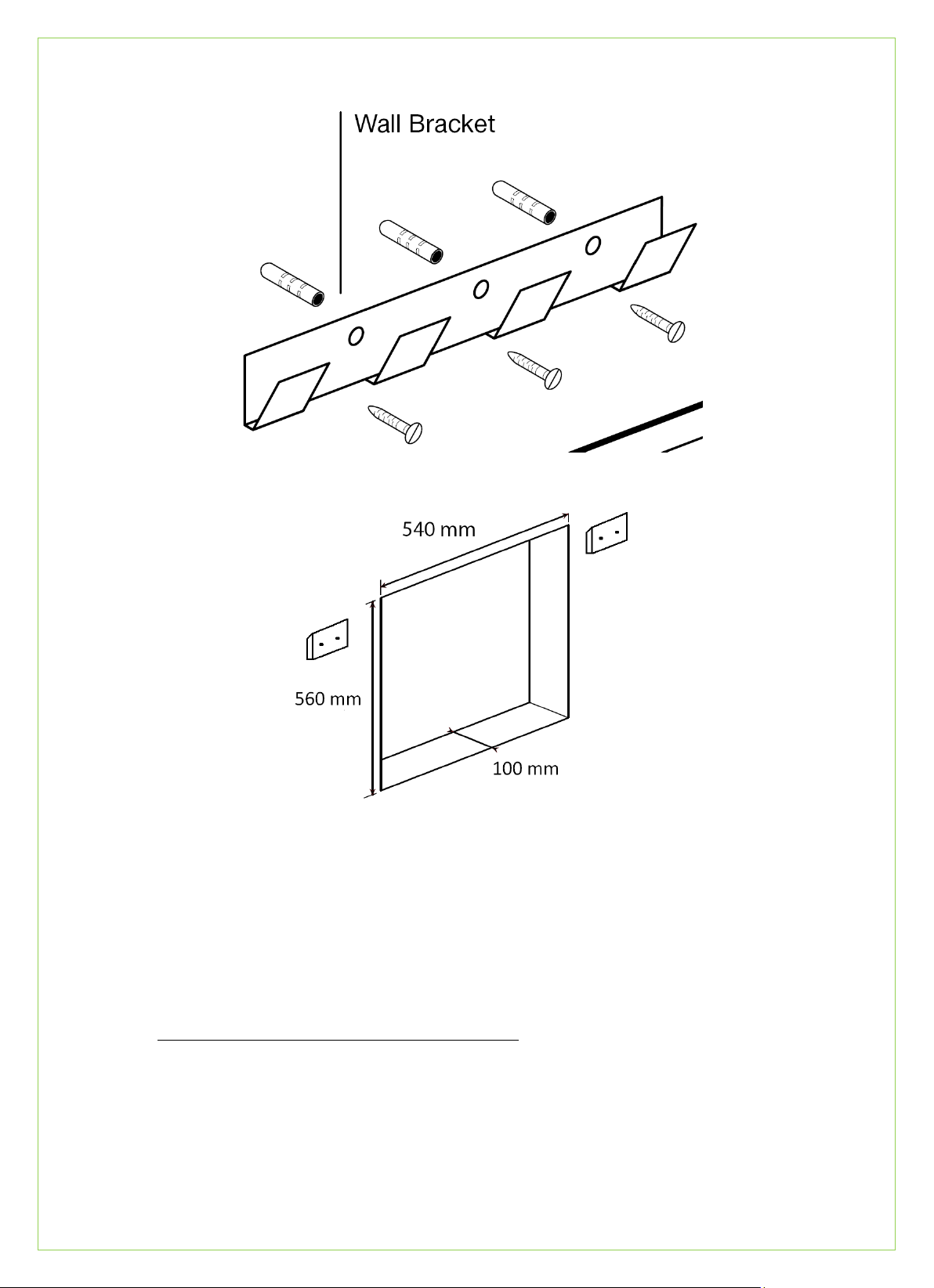
The inset dimensions for Hole in the Wall: depth 10cm, height 56cm and width 54cm. To prevent the fire from being pulled over it must be
secured into place. The height at which you wish to fix the fire to the wall is up to you, though we recommend 60cm from the floor to the bottom
of the fire.
Fig.1
Fig.2
Using as a Hang on the Wall.
The wall bracket should be fixed to the wall with the hooks facing upward and outward (fig.1). The height at which you fix the fire to the wall
should be no less than 60cm from the floor to the bottom of the fire. Once the bracket has been fixed in place, lift and hook the fire onto the
upward facing hooks. At the bottom of the back casing, is a fold out tag. Fold this down so as to expose it under the fire when it is hung in place.
Mark through the hole in the tag; remove fire from its position, drill the hole and fit rawl plug. Hang the fire back on the wall and safely secure.
Using as a Hole in the Wall.
The inset dimensions for Hole in the Wall: 100mm (Depth), 560mm (Height), and 540mm (Width) (fig.2). To prevent the fire from being pulled out
from the wall it must be secured into place. The height at which you fix the fire to the wall should be no less than 60cm from the floor to the
bottom of the fire. Remove the outer spacer frame to expose the fire inner casing. Fasten the MDF wall brackets as in fig.2 using 60mm screws
and large wall plugs. Matching wall brackets are on the back of the Fires front and it may be positioned into the hole, then up and over into place.
Fuel effect Pebbles/coal
Once the fire has been installed in the correct position unpack the pebbles/coals from the accessory box and arrange on the fuel bed.
Page 2 of 3
Page 3
MAINTENANCE
Model identifier (s)
Valiant
Item Symbol
Value
Unit
Heat ou tput
Nominal heat output
Pnom
2.0
kW
Minimum heat output (i ndicative)
Pmin
1.0
kW
Maximum continuous heat output
Pmax,c
2.0
kW
Auxiliary electricity consumption
At nominal heat
elmax
28.5
W
At minimum heat
elmin
28.5
W
In standby
elSB
0.0015
kW
Type of heat output/room temperature control
With distance control option
With electronic room temperature control plus week timer
Yes
Contact detai ls:
Flamerite Fires Ltd. Greenhough Road, Lichfield. Staffs.
WS13 7AU
Before any maintenance/cleaning is undertaken, always disconnect the fire from the mains power supply.
Replacing Lamps (Dimmable 240V 7W 3000k E14 LED lamps): Replacements are available from Flamerite Fires [email protected]
Allow a suitable time for the lamps to cool then remove the glass & fuel effect (see Installation). Remove the two screws from either side of the
fuel bed and lift out of place. Remove and replace the lamps, fuel bed, fuel effect and glass. Please note that replacement Lamps are only covered
from purchase by a 2 year warranty
Cleaning
The fire can be cleaned with a soft damp cloth and none abrasive glass cleaner.
WARNINGS
• Do not open and close the glass repeatedly while the heater is on or the cut out will activate.
• Do not use the fire in the vicinity of a bath shower or swimming pool.
• Never use the fire to dry laundry.
• Never install the fire directly underneath a fixed main socket.
• Never cover the appliance during the operation of the fire.
• The use of an extension lead is not recommended.
• Particular caution should be applied to ensure that children do not play with the fuel effects.
• As with any electrical appliance whilst the instructions aim to cover as many eventualities as possible, caution and common sense should
be applied when operating your appliance, particularly in the vicinity of small children.
Areas around the fire will become hot when activated. We strongly recommend small children be kept away from having any direct
contact with the appliance by means of fitting a fireguard. This appliance is not intended for use by persons (or children) with r educed
physical sensory or mental capabilities or lack of experience or knowledge unless they have been given supervision or instruction
concerning the use of the appliance by the person responsible for their safety. Children should be supervised to ensure they do not
play with this appliance.
PROBLEM SOLVING
• No power to the fire: Check the wall socket, plug, fuse and lamps.
• No illumination: Make sure fire is turned on. Check heater is working, if so check lamps.
• Illumination but heater blowing cold: The safety cut out may have operated. Check for obstruction around the heater. If installed into a
chimney or cavity wall is 100% of drawn air blocked off from the fire.
• Noise when illuminated: Due to moving parts, the electric fire will make a noise.
• Noise from the heater when in use: The sound of rushing air is normal.
RECYCLING
Please recycle responsibly. Take your item to your local recycling centre – you can easily locate your nearest centre on the Recycle Now website or
check with your retailer for details on either a collection service or a store take-back scheme (some may apply charges). Councils may offer a
household recycling collection service for small electrical items; contact your local authority for more details.
Information requirement for electric local space heaters
Room temperature control, with open window detection
Page 3 of 3
 Loading...