

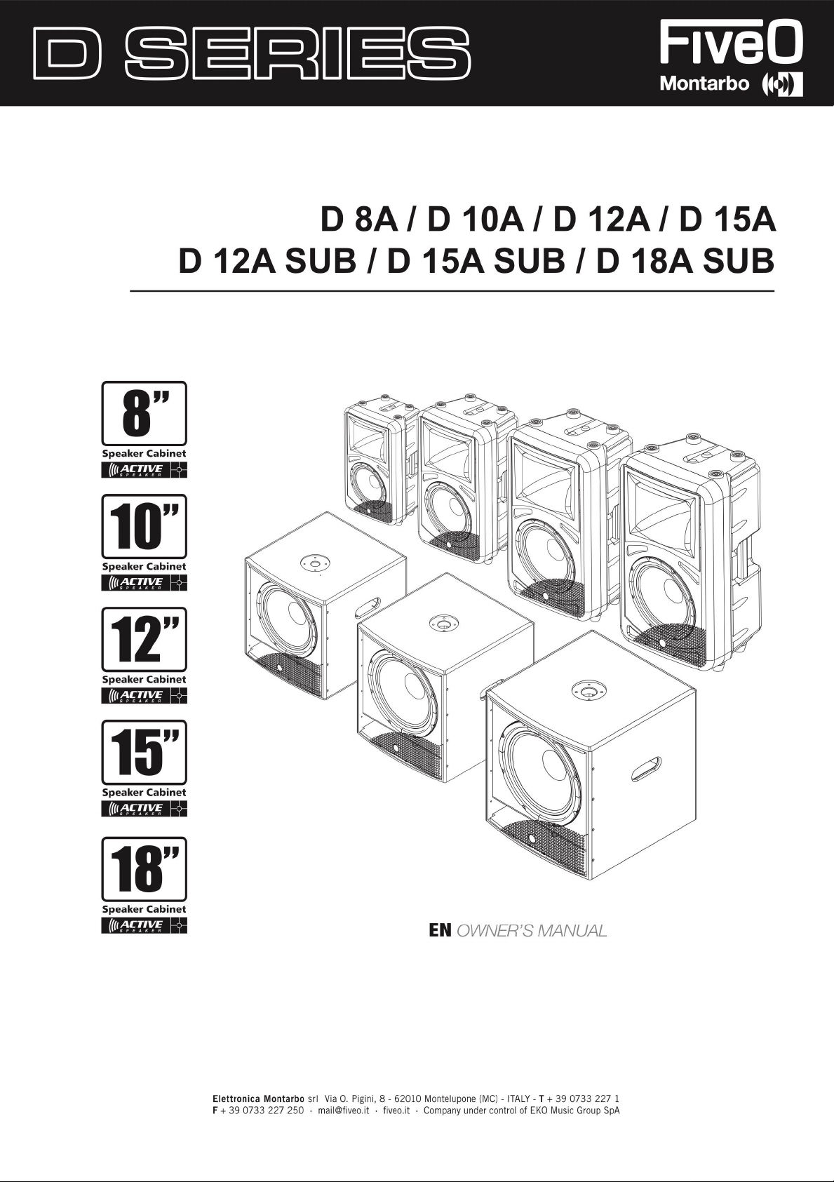
D SA
/
D 10
A
/
D 12
A
/
D 15
A
Speaker Cabinet
1(/IIi&
Speaker Cabinet
Will
ll/liiUDI
D 12
I
A SU
B
/
D 15
A SU
B
/
D 18
A SU
B
Speaker Cabinet
1(/lti&
Speaker Cabinet
l
Speaker Cabinet
Will
l/1Ii&
Will
ll/lii&tQI
I
E
N
OWNER'S MANUAL
Elettronica Montarb
F + 39 0733 227 2
o
srl Via O. Pigini, 8 - 62010 Montelupone (MC) - ITAL
50 · mail@fiveo.it · fiveo.it · Company under control of EKO Music Group SpA
Y - T + 39 0733 227
1
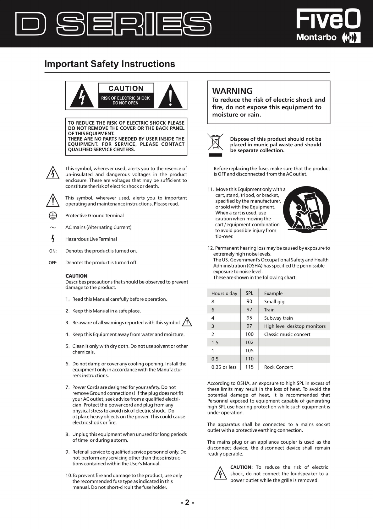
lmportant Safety lnstruction
A
TO REDUCE THE RISK OF ELECTRIC SHOCK PLEASE
DO NOT REMOVE THE COVER OR THE BACK PANE
OFTHIS EQUIPMENT.
THERE ARE NO PARTS NEED
EQUIPMENT. FOR SERVICE, PLEASE CONTAC
QUALIFIED SERVICE CENTERS.
ED BY USER INSIDE TH
A
s
L
E
T
WARNING
To reduce the risk of electric shoc
fire, do net expose this equipment t
moisture or rain
Dispose of this product should not be
placed in municipal waste and shoul
be separate collection
.
.
k and
o
d
This symbol, wherever used, alerts you to the resence o
un-insulated and dangerous voltages in the produc
enclosure. Thes
constitute the risk of electric shock or death.
This symbol, wherever used, alerts you to important
operating and maintenance instructions. Please read
Protective Ground Termina
AC mains (Alternating Current)
Hazardous Live Termina
ON:
Denotes the product is turned on.
OFF
:
Denotes the product is turned off
CAUTION
Describes precautions that should be observed t
damage to the product.
1. Read this Manual care
2. Keepthis Manua
3. Be aware of ali wamings reported with this symbo
4. K
eep this Equipment awayfrom water and moisture.
5. Clean it only wit
chemicals
6. Do not dam
equipment only in a
rer's instructions
7. Power Cords are designed for your safety. Do not
remov
your AC outlet, seek advice from a qualified electri
cian. Protect the power card an
physical stre
ot piace heavy objects on the power. This could cause
electric shodk orfire
8. Unplug this equipment whe
o
f time or during a storm.
9. Refer ali servi ceto qualified servi c
not perform any servicing otherthan those instruc
tions contained within t
1 O.To prevent fire and damage to t
t
he recommend
manual. Do not short-circuitthefus
e are voltages that may be sufficient to
l
l
.
fully before operation
l in a safe piace.
h dry doth. Do not use solvent or othe
.
p or cover any cooling
ccordance with the Manufactu-
.
e Ground co
nnections
ss to avoid risk of electric shock. D
.
he User's Manua
ed fuse type as indicateci in this
opening. lnstall th
!
l
f
t
he plu
d plug from an
n unused for long periods
e personnel only. Do
he product, use only
e holder.
.
o preven
.
l.
g does not fit
-
y
o
l.
f
t
t
,&
r
e
-
-
Before replacing the fuse, make sure that t
is OFF and disconnected from the AC outlet.
1
1. Move this Equipment onlywith
cart, stand, tripod, or bracket,
specified by the manufacturer
or sold with the Equipment.
When a cart is used, us
caution when moving th
cart/ equipment combinatio
to avo id possible injury from
tip-aver.
12. Permanent hearing loss may be cause
extremely high noi se levels
The US. Government's Occupational Safety and Health
Administration (OSHA) has specified th
exposure to noi se leve
These are shown in the following chart
Hours x day
8
6
4
3
2
1.5
0
.5
0.25 or les
According to OSHA, an exposure to high SPL in excess of
these limits may result in the loss of heat. To avoid th
potential damage of heat, it is recommended that
Personnel exposed to equipment capable of generatin
high SPL us
under operation
The apparatus shall be connected to a mains socke
out I et with a protectiv
The mains plug or an appliance coupler is used as th
disconnect device, the disconnect device shal
readily operable
/À.
ili
I
s
e hearin
.
.
CAUTION: To reduce the risk of electric
shock, do not co
power outlet while t
e
l.
SPL
9
0
9
2
9
5
9
7
100
102
105
11 O
115
I
g protection while such equipment is
e earthing co
a
,
e
n
.
Example
Small gi
g
Train
Subway train
High level desktop monitor
Classi
c music conce
Rock Concert
nnection.
nnect t
he loudspeaker to
he grille is removed
he product
d by exposure t
e permissible
:
s
rt
l remain
a
.
o
e
g
t
e
- 2 -

Table of Content
s
1. INTRODUCTION
2. FEATURES
3. BACK PANEL DESCRIPTIO
4. CONNECTIO
5. WIRE C
6. TECHNICAL SPECIFICATIO
N PLATE ------------------------------------------------------------------------------------------------· 7
ONNECTIO
NS
N
NS
4
4
5
1
11
0
- 3 -
lntroductio
T
hank you for choosi
grade solution while maintaini
T
he D Series, depe
churches, conf
p
erformance riv
Our professional Au
years of experience. Gre
and dependable reliability. Also great emphasis is placed in creating and bri
multipl
e applications an
n
ng FIVEO. The new D SERIES cabinets have been designe
ng high quality c
nding on t
erence centers and discos. The woofer and neodymium driver combination provides excellent
aling those cabinet
dio Products are designed and tested by a highly qualified engineering team with more than 3
d offer customers exceptional
he model, can be used for all
s costi
at prid
e
& c
are is placed in deliverin
abinet construction and optimum components
types of applications including, but not limited to,
ng much more
.
g products with excellent p
values.
d to provide a cost effective high
.
erformance, specification
nging to market products that can fil
0
s
i
Every FIV
Feature
• Speakers shoul
speaker stand or equivalent to raise speakers.
• Use professional advice or service when hangin
secure them to prevent them from falling and hurting someone, damaging cabinet or components. Pleas
comply with a
• Use qualit
• For best results match the speakers to a good amplifier that matches the wattage and impedanc
speakers. Proper amplification power results in good quality audio and longer component lite. Check out.
• Avoid pointing microphone directly at an amplified speaker otherwise cou
damaging speaker components and your hearing.
EO Audio p
roduct is teste
d and must comply to
very strict Stan dards
.
s
d b
e plac
ed in
a position that allows for unobstructed sound projection. in many instance
it's beneficiai tor speakers to elevate on tripod stands to achieve maximum dispersion and reach. Consider
g and installing speakers. Please takes precautions to
ll pertinent Regulations
y cables. Using quality cables ensur
.
e best possible sound.
e of you
ld cause feedback possib
s
e
r
le
These series products include active speaker cabinets and subwoofer.
ACTIVE SPEAKERS: D 8A / D 1 OA / D 12A / D 15A
SUBWOOFER: D 12A SUB/ D 15A SUB/ D 18A S
These products are design
such a
s churches, conference center, disco, etc. You can select right model according to your reques
to provide a cost effective hig
UB
h grade solution, and they can be used tor a
- 4 -
ll kinds of applications,
t.
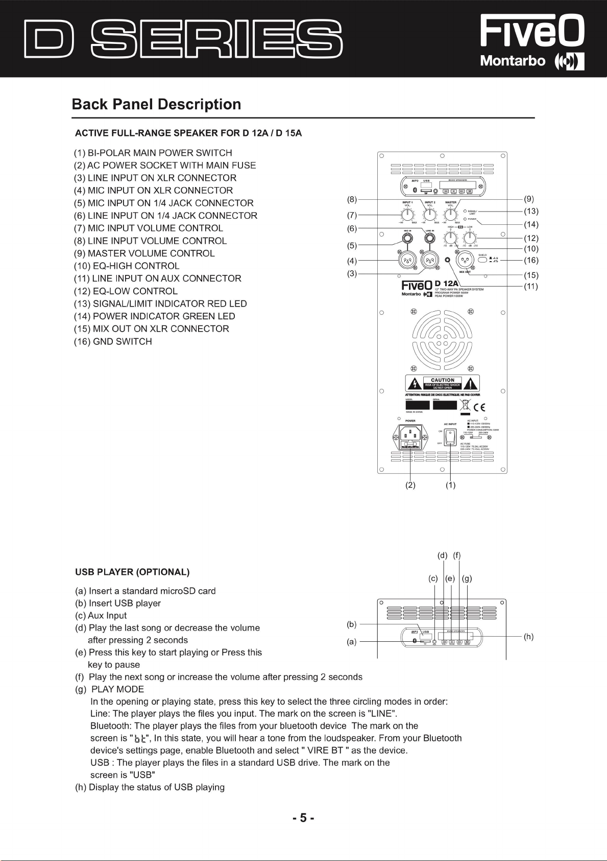
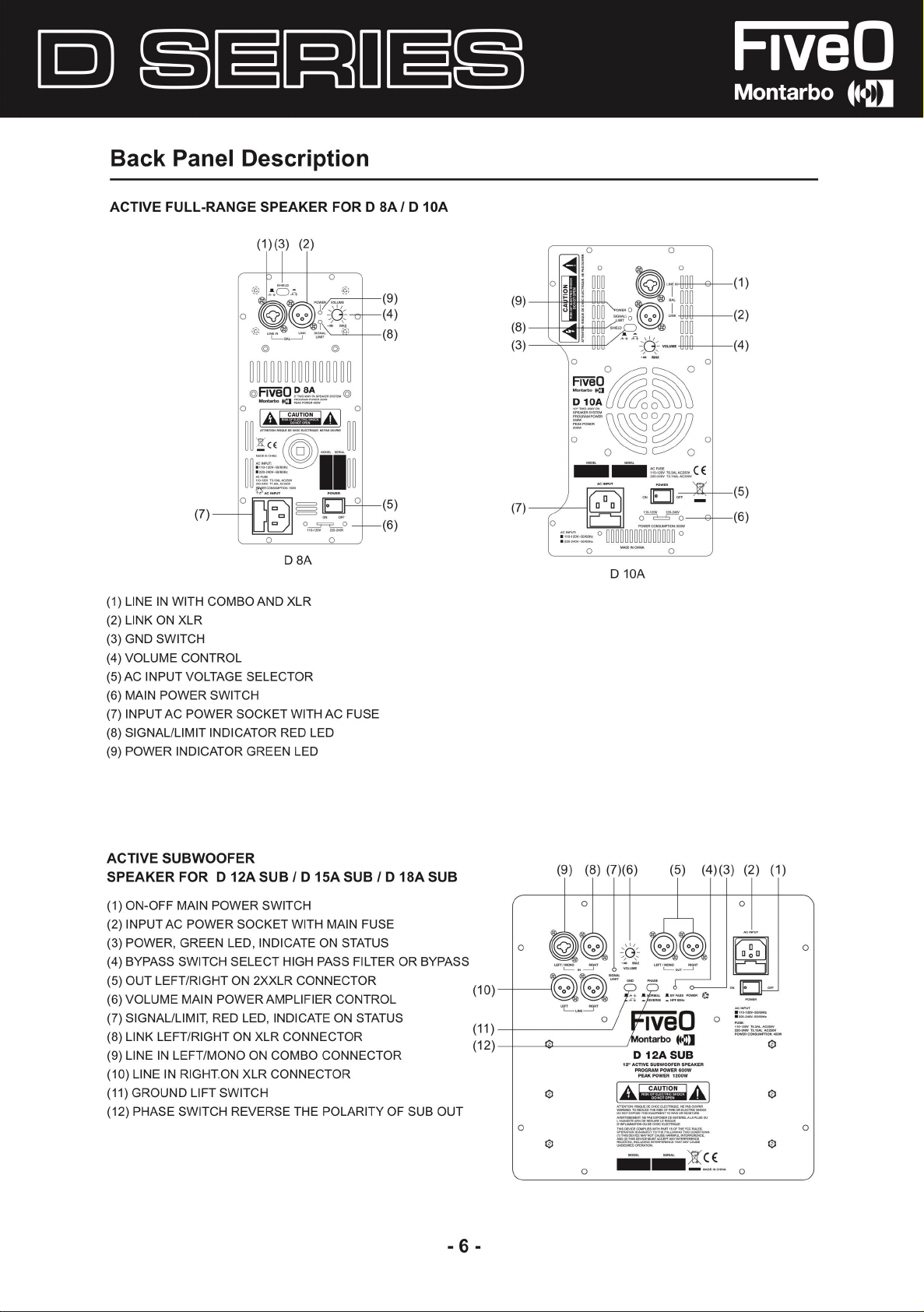
Back Panel Descriptio
n
ACTIVE FULL-RANGE SPEAK
(1) BI-POLAR MAIN POWER SWITCH
(2) AC POW
(3) LINE INPUT ON XLR CONNECTOR
(4) MIC INPUT ON XLR CONNECTOR
(5) MIC INPUT ON 1/4 JA
(6) LINE INPUT ON 1/4 JA
(7) MIC INPUT VOLUM
(8) LINE INPUT VOLUM
(9) MAST
(10
) EQ-HIGH CONTROL
(11) LINE INPUT ON AUX CONNECTOR
(12
) EQ-LOW CONTRO
(13) SIGNAL/LIMIT INDICATOR REO LED
(14
) POW
(15) MIX OUT ON XLR CONNECT
(16) GND SWITCH
ER SOCKET WITH MAIN FUSE
E CONTROL
E CONTROL
ER VOLUM
ER INDICATOR GREEN LE
E CONTROL
L
ER FORD 12A/ D 15A
CK CO
NNECT
CK CONNECTOR
OR
D
OR
(8)
(7)
(6)
(5)
(4)
(3)
o
========
========
========
~ "~' o
o o
o o
[A~,!l~i'-
o
RTBffl0N:
-
....,.
Q
POWE
~
~
..
R
~
-=,,=,
IWQIJE
DIE
-
!;!
CH0C
o
I .,......... I
1,
'i1Hii!
\\1J
ç;j
~
~
A
aa:nlQIJIE.JE-
0UYNI.
)tCE
-
:
......,,., - o.
ACINPUT
PCl'WV'
@~@
@
I
CON
_..,..,_
=
=
=
)
o
o
(9)
(13
(14
(12
(10
(16
(15
(11
)
)
)
)
)
)
)
USB PLAY
(a) lnsert a standard microSD card
(b) lnsert USB playe
(e) Aux Input
(d) Play the last son
after pressing 2 s
(e) Press thi
key to paus
(f) Pl
(g) PLAY MODE
device's settings page, ena
(h) Display
ER (OPTIONAL)
r
g or decrease the volum
econd
s
s key to start playing or Press this
e
ay the next song or increase the volume a
In the openin
Line: The pl
Bluetooth:
screen i
USB : The player plays the files in a standard USB drive. The mark on
screen is "USB"
g or playing state, press this key to selec
ayer plays th
The player plays the files from your bluetooth device
s
"b f.:",
In this state, you will hear a tane from the loudspeaker. From your Bluetoot
the status of USB playing
e files you input.
ble Bluetooth and select" VIRE BT "as
e
fter pressing 2 second
t the thr
The mark on the screen is "LINE"
o
(2)
s
ee circling modes in arder:
.
The mark on th
the device.
the
I
e
0
(d) (f
(e) l(e) I (g)
1
(1)
===
===
===
)
h
o
- 5 -
Back Panel Descriptio
n
ACTIVE FULL-RANGE SPEAK
(1 )(3) (2
@
(7)
(1) LINE IN WITH COMBOAND XL
(2) LINK ON XL
(3) GND SWITCH
(4) VOLUME CONTRO
(5) AC INPUT VOLTAGE SELECTOR
(6) MAIN POWER SWITC
(7) INPU
(8) SIGNAL/LIMIT INDICATOR REO LE
(9) POWER INDICATOR GREEN LE
R
L
H
T AC POWER SOCK
ER FORD SA/ D 10
)
08A
R
ET WITH AC FUS
D
o
-1..;,°''
'--""-
@
D
-'-- (8
E
(9)
(4)
(5)
(6)
A
o
•111111 0
1
___
1
_ --
-
,
~
~
~~~
-tttttt-
.. --~-CE
:;
;:.a•-~~-
(9)
I 11:!lm ~~
)
(8)
(3)
t~r
1!!
~[D-
a a
I
~
(oB
(7)
o
::=::::
o
iii~[~iiiii
o
D 10
;;,,. __
A
·-·
~
o
-z
(1)
(2)
-+--(4)
o
{5}
-
(6)
ACTIVE SUBWOOFER
SPEAK
(1) ON-OFF MAIN POWER SWITC
(2) INPU
(3) POWER, GREEN LED
(4) BYPASS SWITCH SELECT HIGH PASS FILTER OR BYPA
(5) OUT LEFT/RIGHT O
(6) VOLUME MAIN POWERAMPLIFIER CONTROL
(7) SIGNAL/LIMIT, REO LED, INDICATE ON STATUS
(8) LINK LEFT/RIGHT ON XLR CONNECTO
(9) LINE I
(10
(11) GROUND LIFT SWITC
(12) PHASE SWITCH REVERSE THE POLARITY OF SUB OU
ER FOR D 12A SUB/ D 15A SUB/ D 18A SUB
H
T AC POWER SOCKET WITH MAIN FUSE
, INDICATE ON STATU
N 2XXLR CONNECTOR
N LEFT/MONO ON COMBO CONNECTOR
) LINE IN RIGHT.ON XLR CONNECTOR
H
S
R
SS
(10)--+-----\
i~~
~
T
- 6 -
o
I
o
(9) (8) (7)(6
o
'
o
o
)
(5) (4)(3) (2) (1)
1
o
!~t~~
12"ACTIVESUBWOOFERSPEAKE
I A.J.i1~0!'.lJA I
•
=
__,,TO""""""
OO
OOT
l>POOf
,
.
.......,..
..
-.-
_,..,
,..,,. • .......crTO,,.__...., __
"""
""""'
D 12AS
PROG
RAM POWER
P
E.I.KPOWER 1200
TH0-00-°"
T>a
--,
..
...
.,.,,..,.
.,..
.,.
_
...
,.,..
OIJOl!
<MX-~
"""""""''"""_,.,,
~
UB
600
·--ON
l'O
PWN°"~
.,.
...
,._
...,,,.
...,,_,u;
~~~::=
W
W
0llCTIIIC ll«lCI<
.
...
,.....
"'-'LO
R
..,
o
o --
o
;-
o

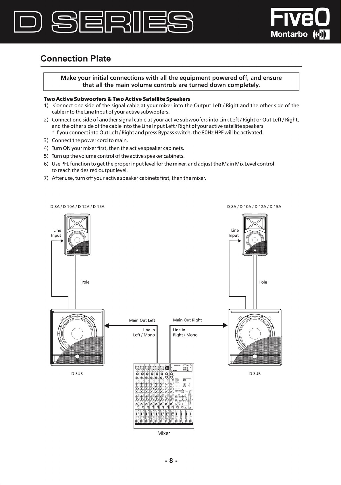
Connection Plat
Mak
e your initial connections with all the equipment powered off, and ensur
that a
ll the main volume controls are turne
e
d down c
ompletely
e
.
For Active Full Range Speaker Syste
1) Connect one side of the signal cable at your mixer into the Output Lef
or XLR) and the other side of the cable into t
(with Stereo Jack or XLR).
2) C
onnect the power card to main.
3) Turn
4) Turn upthevolumecontrol ofthecabinets.
5) Use PFL function to get the proper input level forthe mixer, and adjustthe Main Mix Level
6) After use, turn off your active speaker cabinets
ON your mixer first, then the active speaker cabinets
to reach the desir
D 8A / D 1 DA/ D 1 2A / D 1 S
ed output leve
A
m
l.
Signal Cable
t/ Right (with Stereo Ja
he Line Input (COM BO) of your active speaker ca bi ne
.
first, then the mixer.
D 8A / D 1 DA/ D 1 2A / D 1 S
Signal Cable
ck
t
contrai
A
Tripod
Mount
Left
Main Mix
Outpu
t
Mixe
Right
Main Mi
Output
r
x
Tripod
Mount
- 7 -
Connection Plat
Mak
e your initial connections with a
that a
ll the mai
e
ll the equipment powered off, and ensur
n volume controls are turne
e
d down completely.
Two Active Subwoofers & Two Active Sate
1) Connect one side o
cab
le into the Line Input of your active subwoofers
2) Connect one sid
and the other side o
*
lf you connect into Out Lef
f the signal cable at your mixer into t
e of another signal cable at your active subwoofers into Link Left/ Right or Out Left/ Right
f the cab le into the Line Input Left/ Right of your active sate
t/ Right and press Bypass switch, the 80Hz HPF wi
llite Speakers
he Output Left / Right and the other sid
.
llite speakers.
ll
be activated.
3) Connect the powercord to main.
4) Turn ON your mixer
5
)
Turn up the volume contrai of t
6) U
se PFL function to get the proper input level forthe mixer, and adjust the Main Mix Level contra
first, then the active speak
he active speak
er cabinets
er cabinets
.
.
to reach the desired output level.
7) After use, turn off your active speaker cabinets
D 8A / D 1 DA/ D 1 2A / D 1 S
A
first, then the mixer.
D 8A / D 1 DA/ D 1 2A / D 1 S
e o
f the
,
i
A
D SU
B
Pal
e
Main Out Left
Line in
Left / Mon
Main Out Righ
Line i
o
n
Right/ Mono
t
D SU
B
Pal
e
Mixer
- 8 -
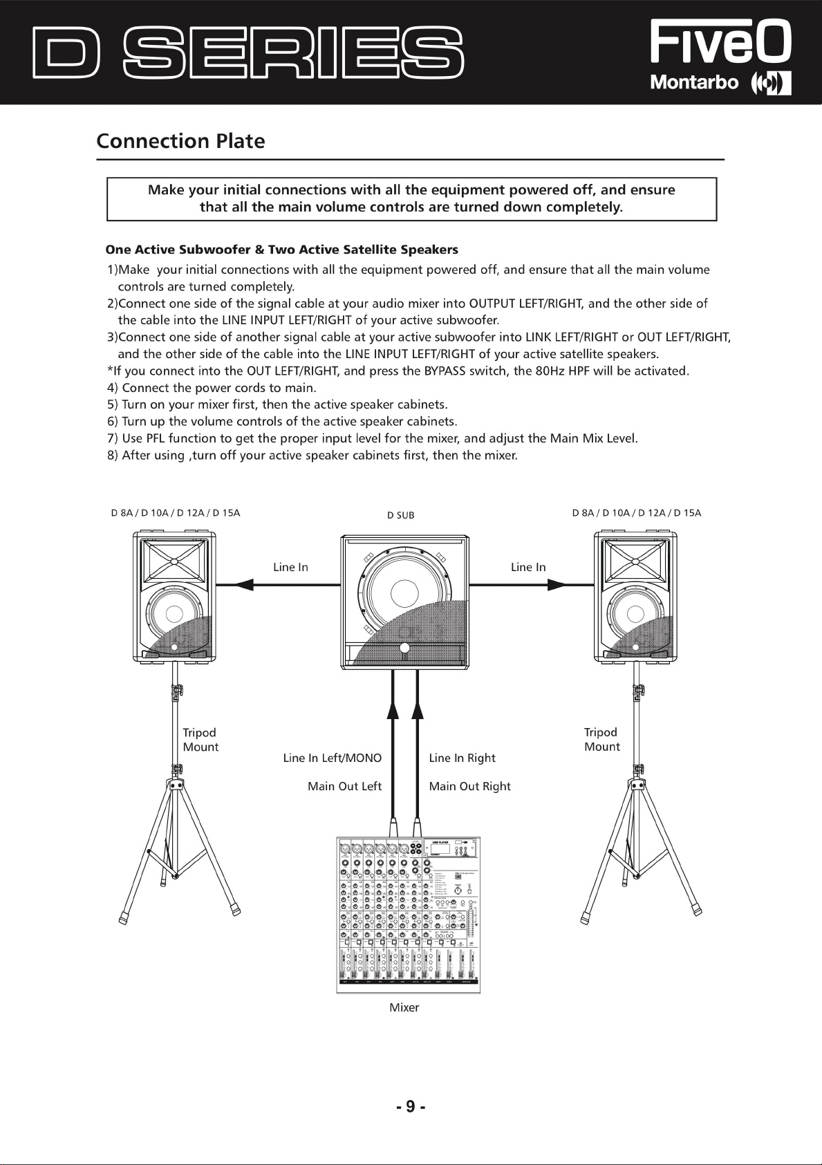
Connection Plate
Mak
e your initial connections with a
that a
ll the mai
ll the equipment powered off, and ensure
n volume controls are turne
d down completely.
One Active Subwoofer & Two Active Sate
1 )Make your initial connections with a
controls are turned completely
li the equipment powered off, and ensure that ali the mai
.
2)Connect one side of the signal cable at your audio mix
the cable into the LINE INPUT LEFT/RIGHT of your active subwoofe
3)Connect one side of another sign
and the other sid
e of the cable into the LINE INPUT LEFT/RIGHT of your active satellite speakers
al cable at your active subwoof
*lf you connect into the OUT LEFT/RIGHT, and pre
4) Connec
5) Turn on your mixer
t the pow
er cords to main.
first, then the active speaker cabinets
llite Speaker
s
er into OUTPUT LEFT/RIGHT, and th
ss the BYPASS switch, th
.
r.
er into LINK LEFT/RIGHT or O
e 80Hz HPF wi
ll
6) Turn up the volume controls of the active speaker cabinets.
7) Use PFL function to get the proper input level for the mixer, and adjust the Main Mix Leve
8) After using ,tu
D SA/ D 10A/ D 12A/ D 15
rn off your active speak
A
Line I
n
er cabinets
D SU
first, then the mixer.
B
Line I
D 8A / D 1 OA / D 1 2A / D 1 S
n
n volum
e other side o
UT LEFT/RIGHT
.
be activated.
l.
e
f
,
A
Tripo
Moun
d
Tripod
Moun
t
Line In Left/MONO
Main Out Left
Mixer
Line In Righ
Main Out Righ
t
t
t
- 9 -
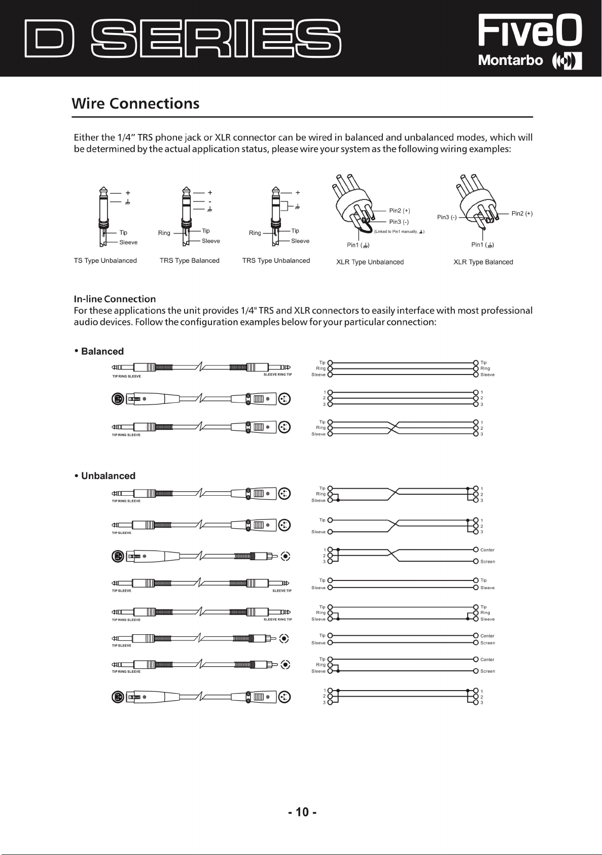
Wire Connections
Either the 1/4" TRS phone jack or XLR connector can be wired in balanced and unbalanced modes, which wil
be determine
i
TS Ty
pe Un
ln-line Connectio
Far these applications th
audio devices. Follow the configuration examples belo
• Balance
d by the actual application status, please wire your system as the following wiring examples
-
,!,
·
Tip
Sleeve
balance
d
n
d
~
4!rr:::::::1
tltll•MIIIIIIII
Rin
TRS Type Balance
-
,!,
t
g
I
·
Tip
Sleeve
d
e unit provides 1/4" TRS an
7
1r===[
·
~
TRS Type Unbalance
~
=
IDIID
~
:
·
~
:
Sleeve
d
d XLR connectors to easily interface with most professiona
w far your particular connection
IP
Sleeve
..
I
©
Sleeve .------
Pin1 (
XLR Type Un
~
s
Ring
~_:_:_:_:_:_:_:_:_:_:_:_:_:_:_:_:_:_:_:_:_:_:_:_:_:_:_:_:_:_:_:_:_:_:_
0
r;,
§ §
Rin
g
.-
------~
Pin2(+)
Pin3 (-)
,J,
)
balance
d
--------
-'
'
--------
c;n
o
_, ~
1
XLR Ty
:
Pin1 (
pe Balance
s
~
-:i
:-i
Rin
steeve
1
---<
2
--<
3
:
~
Ì--
Pin2 (+)
,!,
)
d
g
l
l
• Unbalanced
4i
a:::::::::Jrr11u1m111•m
~
4!rr:::::::1
<ne:::::I
4(
~
®@=•
ti
111111111111
lllllillll
111-m11
11t11
==
r--i-----,,1
L---J-----'
1
HHHHHH
I
~
=:7
,_.......__
~
,
i,
111
lllllllllDl(l]I
11111111@1
li
l=D
mmmom+ I=}=>(•
jj
jjjmjjjjjj+
I=}=>(•
,._""\
\;
.,,
JP
)
)
©
r;,
~
Rin
g
Sleeve ::::::::::::: ~
~~
Sleeve
;
§J
3
~ ~
Sleeve
C
>-
-----------------
Tip
C
>-
-----------------
R
ing
g:::i
Sleeve
Tip
0-
-----------------
Sle
eve
0-
-----------------
Tip
Rin
g
8:::J.
Sleeve
'"*
----------------
:
§J
7
--------
-------
~
_,
~
~-
~
+-,
.. H 3
~
-
--<
--<
--<
~
--<
--<
~
1
2
1
;
~
center
Scree
l Sleeve
l Ti
p
Rin
Slee
J
Center
J
Scree
Center
O S
creen
i
n
g
ve
n
- 10
-

Technical Specificatio
Model Active
System Typ
Program Power Low/Hig
Peak Power Low/High
Transducer Lo
Transducer Drive
Maximum SPL@1 m
Input Sensitivity
Crossover Frequency
Frequency Response
e
h
w
r
ns
2-Way 8" Active Vented Speaker Cabine!
200W Bi-AMP (Low 150W+High 50W-Class AB)
400W Bi-AMP (Low 300W+High 100W-Class AB
8"Woofer -1.5" Voice Coi
1" High D
113dB Max (Calculated
-7dBu
3kH
70Hz - 20kHZ (-10dB)
efinition Neodymium Driver
z
l. with ventilation
)
)
Protection
Input Connectors
External Connector
Power Suppl
Enclosur
Dimension (H x W x D
Net weight
Volum
Model Active
System Typ
Program Power Low/High
Peak Power Low/High
Transducer Low
Transducer Drive
Maximum SPL@1 m
Input Sensitivity
Crossover Fr
Frequency Response
e
e
s
y
)
e
r
equency
Over heat Protection I Short Circuii Protection / Compressor
COMBO - LINE IN/ XLR - LINK
Volume Contrai/ Power on with Gree
Ground Li
110-120V-50/60Hz or 220-240V-50/60Hz Switchabl
Metal gr
16.1 "(410mm) x 10.6"(268mm) x 10.2"(260mm
7.8kg I 17.21bs
1.67 C
D10
2-Way 1 O" Active Vented Speaker Cabine
250W Bi-AMP (low 200W-Class D; High 50W-Class AB)
500W Bi-AMP (Low 400W-Class D; High 100W-Class AB
1 O"Woofer -2" Voice Coi I. with ventilation
1" High D
120dB Max (Calculated)
OdB
2.5kH
65Hz - 20kHZ (-10dB)
ft
ille. ABS Cabine! with rubber foo
FT
A
efinition Neodymium Driver
u
z
n LED/ Clip Limiter / Re
e
t
)
!
)
d LED
/
Protection
Input Connectors
External Connector
Power Suppl
Enclosur
Dimension (H x W x D
Net weight
Volum
e
e
s
y
Over heat Protection I Short Circuii Protection I Compressor
COMBO - LINE IN/ XLR - LINK
Volume Contrai I Power on with Gree
Ground Li
110-120V-50/60Hz or 220-240V-50/60Hz Switchabl
Metal gr
)
20.5"(521mm) x 13.4"(342mm) x 12.2"(310mm
10.1kg / 22.31b
2.94 C
ft
ille. ABS Cabine! with rubber foo
s
FT
- 11
-
n LED/ Clip Limiter / Re
e
t
)
d LED
/

Technical Specifications
Model Active
System Type
Program Power Low/Hig
Peak Power Low/Hig
Transducer Low
Transducer Drive
Maximum SPL@1m
Input Sensitivity
C
rassover Frequency
Frequency Response
Prote
ction
h
h
r
D 12
A
2-Way 12" Active Vented Speaker Cabine!
500W Bi-AMP {low 400W-Class D; High 100W-Class AB)
1000W Bi-AMP {Low 800W-Class D; High 200W-Class AB
12"Woofer -2" Voice Coi
1 "Exit Driver - 1 .4" Compression Driver
122dB Max (Calculated
OdB
u
1.8kHz
60Hz - 20kHZ (-10dB)
Over heat Pratection / Sho
l. with ventila
)
rt Circuii Protection / Compresso
tio
n
)
r
USB Player (optional
Input Connectors
External Connector
Power Supply
Enclosure
Dimension (H x W x D)
Netweight
Volum
e
Model Active
System Type
Program Power Low/Hig
Peak Power Low/Hig
Transducer Low
Transducer Drive
Maximum SPL@1m
Input Sensitivity
C
rassover Frequency
Frequency Response
)
s
h
r
h
With USB&Mirco S
INPUT1-Mic With XLR*1&6.3 Jack*1 / INPUT2-Line With
XLR*1 &6.3Jack*1 &3.5Jack*1
Input 1 &2 and Maste
ON with Green LED / Clip Limiter with Re
Presets
110-120V-50/60Hz or 220-240V-50/60Hz Switchabl
Metal grille. ABS Cabine! with rubber foot
24.3"(618mm) x 16.9"(430mm) x 13.8"(
17.1 kg/ 37.71bs
4.53 CFT
D 15
A
2-Way 15" Active Vented Speaker Cabine!
500W Bi-AMP {low 400W-Class D; High 100W-Class AB
1000W Bi-AMP (Low 800W-Class D; Hig
15"Woofer -2" Voice Coil. with ventilation
1 "Exit Driver - 1 .4" Compression Drive
123dB Max (Calculated
-6dBu
2.2kH
z
50Hz - 20kHZ (-10dB)
D CARD, Bluetooth
r Volume Contrai / 2 Band EQ-High&Low / Powe
)
d LED/ Ground Lift/ DSP
e
350mm
)
h 200W-Class AB
r
r
)
)
Prote
ction
USB Player (optional)
Input Connectors
External Connector
Power Supply
Enclosure
Dimension (H x W x D
Netweight
Volum
e
s
Over heat Pratection / Sho
With USB&Mirco S
INPUT1-Mic With XLR*1&6.3 Jack*1 / INPUT2-Line Wit
XLR*1 &6.3Jack*1 &3.5Jack*1
Input 1 &2 and Maste
ON with Green LED / Clip Limiter with Red LED/ Ground Lift/ DSP
Presets
110-120V-50/60Hz or 220-240V-50/60Hz Switchabl
Metal grille. ABS Cabine! with rubbe
)
27.6"(700mm) x 18.9"(480mm) x 15"(380mm
19kg / 41.91bs
6.45 CFT
- 12
-
rt Circuii Protection / Compressor
D CARD, Bluetooth
h
r Volume Contrai I 2 Band EQ-High&Low / Powe
e
r foo
t
)
r

Technical Specificatio
ns
Model Active
System Type
Program Powe
Peak Powe
Transducer Low
Maximum SPL@1m
Input Level
Active Crossover
Frequency Response
Protectio
Input Connectors
External Connectors
Power Suppl
Enclosure
Dimension (H x W x D
Net weight
Volum
e
r
r
n
y
D 12A S
UB
12" Active Subwoofer Speaker Cabine
600
W
1200W
12"Woofer -3" Voice Coi
123dB Max (Calculated
L-R UNE Input -20dBu
HPF 80Hz Under Analog Processo
45Hz - 160Hz (-10dB)
Over heat Protection / Sho
L-R(COMBO/XLR-F) / L-R UNK(2-XLR-M) / L-R Output (2-XLR-M
Balanced(15k Ohms
Volume Control / Power on with Green LED / Clip Limiter / Red LED /
Groun
d Lift/ Ground Lift/ Phase Switch / HPF 80Hz Bypass
110-120V-50/60Hz or 220-240V-50/60Hz Switchable
Painted MDF Cabine!, Black Metal Gr
)
17.7"(450mm
24.3kg / 53.61b
5.81 C
) x 16.9"(430mm) x 18.11"(460mm)
s
FT
l. with ventilation
)
rt Circuii Protection / Compresso
)
!
r
r
)
ille Protection
Model Active
System Type
Program Powe
Peak Powe
Transducer Low
Maximum SPL@1m
Input Level
Active Crossove
Frequency Response
Protectio
Input Connectors
External Connector
Power Suppl
Enclosur
Dimension (H x W x D
Net weight
Volum
e
r
r
r
n
s
y
e
D 15A S
UB
15" Active Subwoofer Speaker Cabine
600
W
1200W
15"Woofer -3" Voice Coi
124dB Max (Calculated
L-R UNE lnput-17dB
HPF 80Hz Under Analog Processor
40Hz - 150Hz (-10dB
Over heat Protection / Sho
L-R(COMBO/XLR-F) / L-R UNK(2-XLR-M) / L-R Output (2-XLR-M
Balanced(15k Ohms
Volume Control / Power on with Green LED/ Clip Limiter / Red LED /
Groun
d Lift/ Ground Lift/ Phase Switch / HPF 80Hz Bypass
110-120V-50/60Hz or 220-240V-50/60Hz Switchabl
Painted MDF Cabine!, Black Metal Gr
)
20.5"(520mm) x 18.9"(480mm) x 22.2"(564mm
29.3kg/64.61b
8.78 C
s
FT
l. with ventilation
)
u
)
rt Circuii Protection / Compressor
)
!
)
e
ille Protection
)
- 13
-

Technical Specificatio
ns
Model Active
System Typ
Program Powe
Peak Powe
Transducer Low
Maximum SPL@1 m
Input Level
Active Crossove
Frequency Respons
Protection
Input Connectors
External Connector
Power Suppl
Enclosure
Dimension
Net weight
Volum
e
e
r
r
r
y
(
H
x
W x D
D 18A S
UB
18" Active Subwoofer Speaker Cabine
1000W
2000W
18"Woofer -3" Voice Coil. with ventilation
128dB Max (Calculated
L-R LIN
E
lnput-17dB
HPF 80Hz Under Analog Processor
e
s
)
35Hz-150Hz (-10dB
Over heat Protection / Short Circuii Protection / Compresso
L-R(COMBO/XLR-F) / L-R LINK(2-XLR-M)
Balanced{15k Ohms)
Volume Contrai / Power on with Gree
Ground Lift/ Ground Lift/ Phase Switch / HPF 80Hz Bypas
110-120V-50/60Hz or 220-240V-50/60Hz Switchable
Painted Plywood Cabine! with Rubber Feet, Blac
24.6"(625mm) x 20.5"(520mm) x 22.8"(580mm)
33.6Kg / 74.1 lb
11.68 CFT
)
u
)
s
!
r
/
L-R O
utput (2-XLR-M
n LED / Clip Limiter / Red LED
k Metal Grille Protection
s
)
/
- 14
-

- 15
-

EN
The informati
and checked However no responsibility wi/1
incorrectness. This manua
whic
h may arise during
on contained in this manua/ have been carefully drawn u
/ cannot cover a
be assume
l/
the possib/e contingencie
d far an
the product installation and use. Shou/d further
p
y
s
information be desired, p/ease contact us or our loca/ distributor
Elettronica Montarbo srl ca
whic
h may
be caused to peop/e and things when using this produc
n not be considered responsible far damag
es
t.
Specifications and features are subject to change without prior notice
Elettronica Montarb
F
+ 39 0733 227 250 · mail@fiveo.it · fiveo.it Company un
o
srl Via O. Pigini, 8 - 62010 Monte
lup
one (MC) - ITAL
der control of EKO Music Group SpA
Y -
T
+
3
9 0733 227
1

D SA
/
D 10
A
/
D 12
A
/
D 15
A
Speaker Cabinet
(«1Ii&ttll
Speaker Cabinet
lri&
f.i&Will
D 12
l
A SU
B
/
D 15
A SU
B
/
D 18
A SU
B
Speaker Cabinet
lri&Ii&U:111
Speaker Cabinet
l«IIiEU:11
Speaker Cabinet
lri&ti&
1
Will
Il
MANUALE UTENT
E
Elettronica Montarbo srl Via O. Pigini, 8 - 6201 O Montelupone (MC) - ITALIA - T
F + 39 073
3 227 250 - mail@fiveo.it · Società controllata da Eko Music Group Sp
+ 39 0
733 227
a
1

Informazioni sulla Sicurezz
A
PER RIDURRE IL RISCHIO DI SCOSS
INVITIAMO A NON RIMUOVERE IL COPERCHIO O IL
PANNELLO POSTERIORE DI QUESTO DIS
ALL'INTERNO NON SONO PRESENTI PARTI UTI
L'UTENTE. PER L'ASSISTENZA RIVOLGETEVI A CENTRI
SPECIALI
ZZATI.
Questo simbolo, ovunque appaia, avverte della presenza d
tensioni pericolose e non isolat
intensità su
morte.
Questo simbolo, ovunq
operative e di manutenzione. Leggetele!
Terminale di tema di protezione.
Corrente AC (Corrent
Terminale attivo pericoloso
Indica che il disposivio è acceso.
ON:
Indica che il dispositivo è spento.
OFF:
AWERTENZA
Descrive le precauzioni da osservare per prevenire danni al
dispositivo.
1
. Leggete attentamente questo Manuale prima dell'utilizzo
2. Conservate questo Manuale in
3. Rispettate tutte le avvertenze contrassegnate da
4. Conservate
5. Pulit
6. Non bagnate nè ostruite le aperture di ventilazione.
7. I cavi di alimentazione sono progettati per la vostra
8. Scollegate
9. Per l'assistenza rivolgetevi a
10. Per evitare incendi e dann
fficiente da costituire rischio di scosse elettriche
ue appaia, segnala importanti istruzion
e alternata)
.
il dispositivo lontano da acq
e esclusivamente co
utilizzate solventi o altri prodotti chimici.
Installate il dispositivo i
Produttore
sicurezza. Non rimuovete la messa a terra!
non è compatibile con la vostra presa AC, richiedete
l'intervento di un elettricista qualificato. Proteggete il
cavo e la sp
rischio di scosse elettriche. Non schiacciate
oggetti pesanti, per evitare scosse elettriche o incendi
inutilizzo prolungato o durante un
effettuate int
operative.
esclusivamente fusibili del tipo indicato in questo manuale.
Non mettete in cortocircuito
.
ina da qualsisi stre
il dispositivo dalla rete elettrica in caso di
erventi tr
n un panno asciutto. Non
n base alle istruzioni del
anne quelli descritti nelle istruzion
il portafusibile
E ELETTRICHE VI
POSITIVO.
e all'interno del prodotto d
.
un luogo sicuro
ua
e umidità
ss fisico per evitare il
temporale
un cent
i al prodotto, utilizzat
.
ro qualificato. Non
.
a
LI PE
.
Se la sp
il cavo co
.
ina
.
R
i
i
o
i
.
n
i
e
- 2 -
ATTENZIONE
Per ridurre il rischio di scosse elettriche
incendio, no
dispositivo a piogg
n esponete
ia e umidità
Non smaltite questo prodotto come un
comune rifiuto domestico ma
conferitelo in
differenziata.
un centro per la raccolt
,
e
questo
-
Prima di sostituire il fusibile, assicuratevi che
spe
nto e scollegato dalla rete elettrica.
11. Spostate il dispositivo solo con un
carrello, supporto, cavalletto
staffa specificati dal produtto
v
enduti con il dispositivo. Se
utilizzate un carrello, fate
attenzione durante lo spostament
della combinazione carrello /
dispositivo per evitare lesioni d
ribaltamento
12. L'esposizione a livelli di rumo
causa
governativo USA per la sicurezza e la salute su
specificato i
Questi sono indicati nella tabella seguente:
[ Ore x giorno SP
I
l
I
I
0.2
L'esposizione a livelli di pressione sonora (SPL) olt
limiti può causare perdita di udito. Per evitare potenziali danni
all'udito si raccomanda l'ut
personale esposto a dispositivi in gra
livelli di pressione sonora, quan
funzionanti.
Il dispositivo deve essere collegato a una presa di rete dotata
di messa a terra.
La sp
ina si ut
elettric
a e dev
/À.
ili
.
re perdita di udi
tempi masssimi di esposizione al rumore.
L
8 90 Piccolo concert
6
4
3
2
1.5
0.5
5 o me
ATTENZIONE: Per ridur
elettriche, non collegate il diffusore
corrente se l
9
2
95 Metropolitana
9
7
100 Concerto musicale classico
102
105
110
no 115 Concerto Rock
ilizz
a per scollegare il dispositivo dalla ret
e essere sempre raggiungibile.
a grigl
re
re estremamente elevati p
to permanente. L'OSHA, ent
Tre
no
monitor high-leve
ilizz
o di protezioni da parte de
do tali dispositivi son
re il rischio di scosse
ia è stata rimossa
il dispositivo sia
o
o
o
a
l lavoro, h
Esempio
o
I
I
l
I
I
I
re quest
do di generare elevati
a una presa di
.
uò
a
e
a
i
l
o
e

Indic
e
1. INTRODUZIONE-----------------------------------------------------------------------------------------------------
2. CARATTERISTICHE
3. DESCRIZIONE PANNELLO POSTERIOR
4. COLLEGAMENTI
5. CABLAGGI
6. SPECIFICHE TECNICHE---
O
-----------------------------------------------------------------------------------------
E
- 1
4
4
5
7
1
0
1
- 3 -

Introduzione
Grazie per aver scelto FIVEO. I nuovi cabinet D SERIES sono stati p
ad alte p
Le unità D Series, in bas
in chiese, centri congressi e discoteche. La combinazio
eccellenti, i
I nostri Prod
anni di esperienza. M
specifiche
soddisfare applicazioni multiple e offrir
Ogni prodotto Audio FIVEO è testato per soddisfare norme molto severe
Caratteristic
• Assicuratevi di sistemare i diffusori in u
• Affidatevi a u
restazioni, mantenendo la qualità nella costruzio
e al modello, posso
n grad
o di c
ompetere con quelle di cabi
otti Audio professionali sono progettati e testati da un team di ingegneri altamente qualificati, con oltr
ettiamo gr
e affidabilità credibili. Co
and
no essere utilizzate per applicazioni di qualsiasi tipo, incluse installazion
e orgoglio e cur
n grand
e entusiasmo creiamo e presentiam
e ai clienti un valore eccezionale
ne dei cabinet
ne di
net di maggior prezzo
a nella realizzazione di prodotti con p
he
na posizione che consenta di proiettare
molti casi, per ottenere l
Utilizzate supporti per diffusori o dispositivi equivalenti per sollevare le unit
n consulente o a un service professionale per appendere e installare i diffusori. Prendete tutte
le precauzioni per evitare che le unità possano cadere e ferire qualcuno, oltre a danneggia
componenti. Vi invitiamo a rispettare tutti i regolamenti pertinenti
a massim
a dispersione e portata,
rogettati pe
e nella scelta dei componenti
woofer e driver al neodimio assicura p
.
.
.
è utile posizionare i diffusori su appositi supporti
.
r fornire una soluzio
o al pubblico prodott
il suono senz
à.
ne conveniente
.
restazion
e 3
restazioni eccellenti
i i
n gra
do di
a ostacoli. I
re i cabinet o i
n
i
i
0
,
.
• Usate cavi di qualità. L'ut
• Per ottenere risultati ottimali, abbinate i diffusori a
corrispondenti a quelle dei diffusori. Una potenza di amplificazione adeguata si tr
qualità e maggior durata dei componenti. Veri
• Non puntate il microfono direttament
potrebbe danneggiare i componenti del diffusore e
Questa serie comprende casse ampli
DIFFUSORI ATTIVI: D 8A / D 10A / D 12A / D 15A
SUBWOOFER: D 12A SUB / D 15A SUB / D 18A SUB
Q
uesti prod
per qualsiasi tipo di applicazione, come installazioni in chiese, centri congressi e discoteche. Scegliete il modello
giusto in base alle vostr
otti sono progettati pe
ilizz
o di cavi di qualità assicura
r fornire una soluzione conveniente ad alt
e necessità.
ficate sempre tutte le caratteristiche dei dispositivi.
e verso un diffusore ampli
il vostro udito.
ficate e subwoofer.
il miglior suono possibile.
un buon amplificatore co
ficato, per evitare
e p
restazioni e possono esse
n potenza e impedenza
aduce in audio di buona
il prodursi di feedbac
k che
re utilizzat
i
- 4 -

Descrizione Pannello Posteriore
SPEAKER FULL-RANGE ATTIVI - D 12A / D 15A
(1) INTERRUTTORE DI ACCENSIONE BI-POLAR
(2) INGRESSO PER IL CAVO DI CORRENTE CON FUSIBILE
(3) CONNETTORE XLR LINE INPUT
(4) CONNETTORE XLR MIC INPUT
(5) CONNETTORE JACK DA 1/4 MIC INPUT
(6) CONNETTORE JACK DA 1/4 LINE INPU
(7) CONTROLLO VOLUME MIC INPUT
(8) CONTROLLO VOLUME LINE INPUT
(9) CONTROLLO VOLUME MASTER
(10) CONTROLLO EQ HIGH
(11) C
ONNETTORE AUX LINE INPU
(12) CONTROLLO EQ LOW
(13) INDICATORE LED ROSSO SEGNALE/LIMITE
(14) INDICATORE LED VERDE ALIMENTAZION
(15) CONNE
(16) INTERRUTTORE GND
TTOR
E XLR MIX OUT
T
E
T
E
(8)
(7)
(6)
(5)
(4)
(3)
'
O
========
========
========
~® ·;'
o o
o
[A~r!il!
o o
R11NT10N:
-
......
Q
POWE
o
(2)
~
~
..
R
I
~
o
"7
-..
!;11
Dl!
-
CHOC
o
I ~""""'"' I
!iiiltmw
~
~
~
1
N
@:J.A.
..:t!IQUE.ta-
OUYMI.
)tCE
-
:,~<W.
ACIM
PUT
-·-
®
~
===
===
===
o
j
(1)
=
=
=
®
~
J
~
®
-
o
o
o
(9)
(13
(14)
(12)
(10)
(16
(15
(11)
)
)
)
LETTORE USB OPZIONALE
(a) Inserite qui una microSD standard
{b) Collegat
(c) Ingresso Aux
(d) Quest
premuto per oltre 2 secondi
(e) :remet
in
(f) Quest
se premuto per oltre 2 secondi.
(g) Modalità PLAY
I
n apertura o durante la riproduzione, premet
Line
Bluetooth
ode un to
selezionate "VIRE BT" come dispositivo.
USB
(h) Indica lo stato del lettore USB
e qui il lettore USB.
.
o pulsante riproduce l'ultimo brano
e questo pulsante per avvia
pausa.
o pulsante riproduce il brano successivo o aumenta il volume
.
:
li
lettore riproduce i file in ingresso. Sullo scher
:
li
l
ettore riproduce i file dal dispositivo Bluetooth. Sull
no dallo speaker. Dall
:
li
l
ettore riproduce i file provenienti da un'unità USB standard. Sullo schermo appare "USB".
.
.
re la riproduzione
.
(d) (f
)
(e) l(e) I (g
o
o abbassa il volume s
o per mettere (a
e questo pulsante per selezionare una delle tre modalità seguenti:
mo a
a pagina delle impostazioni del dispositivo Bluetooth, attivate Bluetooth e
e
(b)
)
ppare "LINE".
o scher
,
(
"~'
t;ì:1 :::··
mo apparirà
i
"
b
)
t
t
l
i
:
I
)
I:",
I
n questa modalità s
I
(h)
- 5 -
i

Descrizione Pannello Posteriore
SPEAKER FULL-RANGE ATTIVI - D SA/ D 10A
(1)(3) (2
@ @
(7)
(1) UNE IN CON COMBO E XLR
(2) LIN
K TRAMITE XLR
(3) INTERRU
(4) CONTROLLO VOLUME
(5) SELETTORE DI TENSIONE DI CORRENTE
(6) INTERRUTTOR
(7) INGRESSO PER IL CAVO DI CORRENTE CON FUSIBIL
(8) INDIC
(9) INDIC
TTORE GN
ATORE LED R
ATORE LED VERDE ALIMENTAZIO
D
E DI ALIMENTAZION
OSSO SEGNALE/LIMITE
)
(5
(5)
(6)
D 8A
E
NE
E
(7)---,,'--
o
:::::::
-;
0
:
o -·
o
~
iiii!Hiiiii
-
D 10
A
""'" -1
o
----Bl----(6
0
i
o
(5)
)
SUBWOOFER ATTIVO - D 12A SUB/ D 15A SUB/ D 18A S
(1) INTERRU
(2) INPUT INGRESSO PER IL CAVO DI CORRENTE CON
FUSIBIL
(3) INDICATORE LED VERDE DELLO STATO
DELL'ALIMENTAZIONE
(4) INTERRUTIORE BYPA
BYPASSARE IL FILT
(5) DUE CONNETTORI XLR D'USCITA LEFT/RIGHT
(6) CONTROLLO VOLUME PRINCIPAL
DELL'AMPLIFICATORE DI POTENZ
(7) INDICATORE LED R
(8) LINK TRAMITE CONNETTORE XLR
(9) CONNETTORE COMBO UNE IN LEFT/MONO
(1 O) CONNETTORE XLR UNE IN RIGH
(11) INT
(12) INTERRU
DELL'USCIT
TTORE DI ACCENSION
E
SS PER SELEZIONARE O
RO HIGH PAS
OSSO SEGNALE/
ERRUTTORE GROUND LI
TTORE PHASE PER INVERTIRE LA POLARITA'
A SUB
E
S
E
A
LIMIT
T
FT
E
- 6 -
UB
( 1 O
)
--+----<
(11)-1-
(12)-1--.....,__--~
(9) (8) (7)(6
o o
1
1
~
~,~
I'.'... _ _;
---
o
-
o
o
o
) (5) (4 )(3) (2
1
1
~
o ~ ~ ~::
12"AC
[A.J,o,,NJ,;JAJ
.
-T0""""""--"'-""a.o<
""
""'_,_
__ ..
, . ....,.,..
·-""""
_,<*.-....&'TTOTHI __
--"'-"H->MT100,
=,
_
- ·- )tC
::: - " o ~- -
1veO ~;~-
lontarb
o
m
D 12ASU
PROQRAM POWE
,,
-=..----
B
TIVESU8WOOl'l:RSPEAKE
R
eoow
P
EAII POWER 1200W
""
"""'
..
...
_,.m ....
..,
....
... _OE
__ •"'
..
""
...,._
....
......
""""
~
THf
><:C
_
___ ,_
.,.,,_
"""
n..
_
-
) (1)
11
~
1
-
D
o
R
..x><
""'"
"'
E
o
o
o
o

Collegamenti
Prima di effettuare i collegamenti assicuratevi che tutti i dispositivi siano spenti e con
tutti i contro
Per un Sistema di Speaker Full Range Attivo
1
)
Collegate un lato del cav
l'altro lato del cavo al Line Input (COMBO) della cas
2
)
Collegate
3
)
A
ccendete prima
4
)
Ruotate
5
)
Utilizzate la funzio
il cav
o di cor
il controllo di volume dei cabine
Mix Level per raggiungere il livello di uscita desiderato.
6
)
Dopo l'uso, spegnete prima le casse ampli
o di s
egna
rente alla rete elettrica
il mixer, poi l
ne
PFL
e cass
per ottenere il livello di ingresso corretto per il mixer e regolate il controllo Main
lli di volume completament
e abbassat
i.
le all'uscita mixer sinistra/ destra (con presa jack Stereo o XLR)
sa attiva (con presa jack Ste
reo o XLR).
.
e amplificate.
t.
ficate, poi il mixer.
e
D 8A/ D 10A/ D 12A/ D 15
Treppiede
A
Cavo c
he porta
il segnal
Uscita
Main Mix
Sinistr
e
a
Cavo c
he porta il segnale
Uscita
Main Mix
Destr
a
D 8A/ D 10A/ D 12A/ D 15
Treppie
de
A
Mixer
- 7 -

Co I legament
i
Prima di effettuare i collegamenti a
ssicuratevi
che tutti i dispositivi sia
no spenti
con tutti i controlli di volume completamente abbassati.
Due Subwoofer Attiv
1
)
Collegate un lato del cavo di segnale all'uscita del mixer sinistra/ destra e l'altro lato del cav
dei vostri subwoofer attivi.
2
)
Collegate un lato di u
Left/ Right e l'altro capo del cavo nel Line Input Left/ Right dei vostri satelliti
* Se vi collegate alla presa Out Left/ Right e premete l'interruttore Bypass, verr
3) Collegate
4
)
Accendete prima il mixer, poi gli speake
5) Ruotate
6) Utilizzate la funzione PFL per ottenere il livello di ingresso corretto per il mixer e regolate
M
ix Level per raggiungere
7
)
Dopo l'uso, spegnete prima l
D BAI D 10AI D 12AI D 15
il cavo di corrent
il controllo di volume dei cabinet.
i & Due Sate
n altro cavo di s
e alla rete elettrica
il livello di uscita desiderato.
e casse amplificate, poi il mixer
A
lliti Attiv
egna
i
le ai vostri subwoofer attivi nella presa Link Le
.
à attivato
.
r cabinet a
ttivi.
.
D BAI D 10AI D 12AI D 15A
e
o al Line Input
ft/ Right o Ou
il
filtro 80Hz HPF.
il controllo Main
t
D SU
B
Pal
o
Uscita Main Sinistra
Line I
Sinistra I Mo
no
n
Mixer
Uscita Ma
Line I
Destra I Mon
in Destra
n
o
D SU
B
Pal
o
- 8 -

Collegamenti
Prima di effettuare i collegamenti assicuratevi c
con tutti i controlli di volume completamente abbassat
Un Subwoofer Attiv
1) Effettuate i
completament
2) Collegate
un lato del cav
INPUT LEFT/RIGHT del vost
3) Collegate un lato di un altro cav
LEFT/RIGHT e l'altr
*Sevi collegat
4
) Collegate il cav
5) Accendete prima
6
) Ruotate il cont
o & D
ue Satelliti Attivi
collegamenti iniziali con tutti i dispositivi spenti, assicurandovi che tutti i controlli di volume sia
e abbassati
.
o di s
egna
le all'uscita del mixer OUTPUT LEFT/RIGHT e l'altro lat
ro
subwoofer attivo.
o di segnale al vost
o capo del cavo nel LINE INPUT LEFT/RIGHT dei vostri sate
e alla presa OUT LEFT/RIGHT e premete l'interruttore BYPASS, verrà attivato il filtr
o di cor
rente alla rete elettrica
il mixer, poi gli speaker cabinet attivi.
rollo del volume dei cabine
7) Utilizzate la funzione PFL per ottenere i
Level.
8) Dopo l'uso, spegnet
D BAI D 1DA/ D 12A/ D 15
e prima le casse amplificate, poi il mixer.
A
ro subwoofer attivo nella presa LINK LEFT/RIGHT o OUT
.
t.
l livello di ingress
D SU
B
he tutti i dispositivi siano spenti
o corretto per
i.
o del cavo al LINE
lliti
.
il mixer e regolate il cont
D BAI D 1DA/ D 12A/ D 15
e
o 80Hz HPF
rollo Mai
n Mix
A
no
.
Li
ne In
Li
ne In Sinistra/MON
Uscit
a Main Sinistra
O
Li
ne In Dest
Uscita Main Destra
ra
Line In
Mixer
- 9 -

Cablaggio
È possibile cablare una presa jack pho
base alle applicazioni. Cablate il vost
-
,j,
i
·
Tip
Sleeve
Tipo T
S Sbilanciat
Coll
egamento ln-
Per queste applicazioni l'unità fornisce connettori TRS
part
e dei dispositivi audio professional
particolari:
• Bilanciat
o
<lt
~
<m:::::1
o
line
t
lli··illdll
Rin
Tipo TRS Bilancia
g
f
ffii
-
,j,
Tip
'
Sleev
,
1r===1
ne TRS da 1/4" o un connetto
ro sistema come illustrato
:
e
to
Tipo TRS Sbilanciato
i. Seguit
=
"""
=i-T:
Sleeve
e gli esempi di configurazione successivi per i vostri collegamen
lIIIID
..
I
©
re XLR in modo bilanciato o sbilanciato, i
:
~
Pin2(
Pi
n3 (-
+)
0
)
;00 , _, ~
"-
ì--
Pin2 ( +
·
Pin1 (
,j,
___, Ring
g
~
---<
[) Sleeve
;
1
H
2
3
)
Pin1 (
,j,
)
Tipo XLR Sbilancia
da 1/4" e XLR per interfacciarsi facilmente con la maggio
Rin
g
~
g
Sleeve C >------------------
;
g g
T;p
§ §
Ring f--
e
>--
----}(:
---
Sleev
to
------
~
~
-----
Tipo XLR Bilanciato
----<
n
)
r
ti
• Sbilanciat
~
~ ~
<m:::::i
~
<m:::::1
o
.---il
nTTlmlll
m:::
==
jjjjjjjj
jjjj
jjjj
r--i-------,1
L-J--"
Il
Il
••IIINII
MH 1
llll[+t1i111
1
11c:::::::C
~
~
l
1
iiii•iill•[
7/
1
1
1lt
jjjjjjjjjnjjj+ ~ (•
=
11
omooom+
UIIID
•
11
lIIIID
•
I
©
"•"
\:
l=JJ)t,
)
~ (•
)
©
r;p
Rin
Sleeve ::::::::::::
r;p
Sleev
',/
Tip ~~
Sleev
Tip C >-
R;o
Sleev
Tip ~~
Sleev
Sleev
Tip
Ring8:l
)
s:i
g
~
e
>--
-----
;
g3
3
::::::::::::::::::::::::::::::::::::~ Ti
e
------------------<I I Ti
g
8:l
e
------------------4,_.
::::::::::::::::::::::::::::::::::::~ Cente
e
e
.-.
----------------
:
§J
~
-------
:
,-
------
~
~
><
'--
-
---i
--<
-
~
H
Il-<
~
~
---<
~
1
2
3
1
;
~
center
Screen
p
Sleeve
p
R;o
g
Slee
Scree
Center
O
Screen
i
ve
r
n
- 10
-
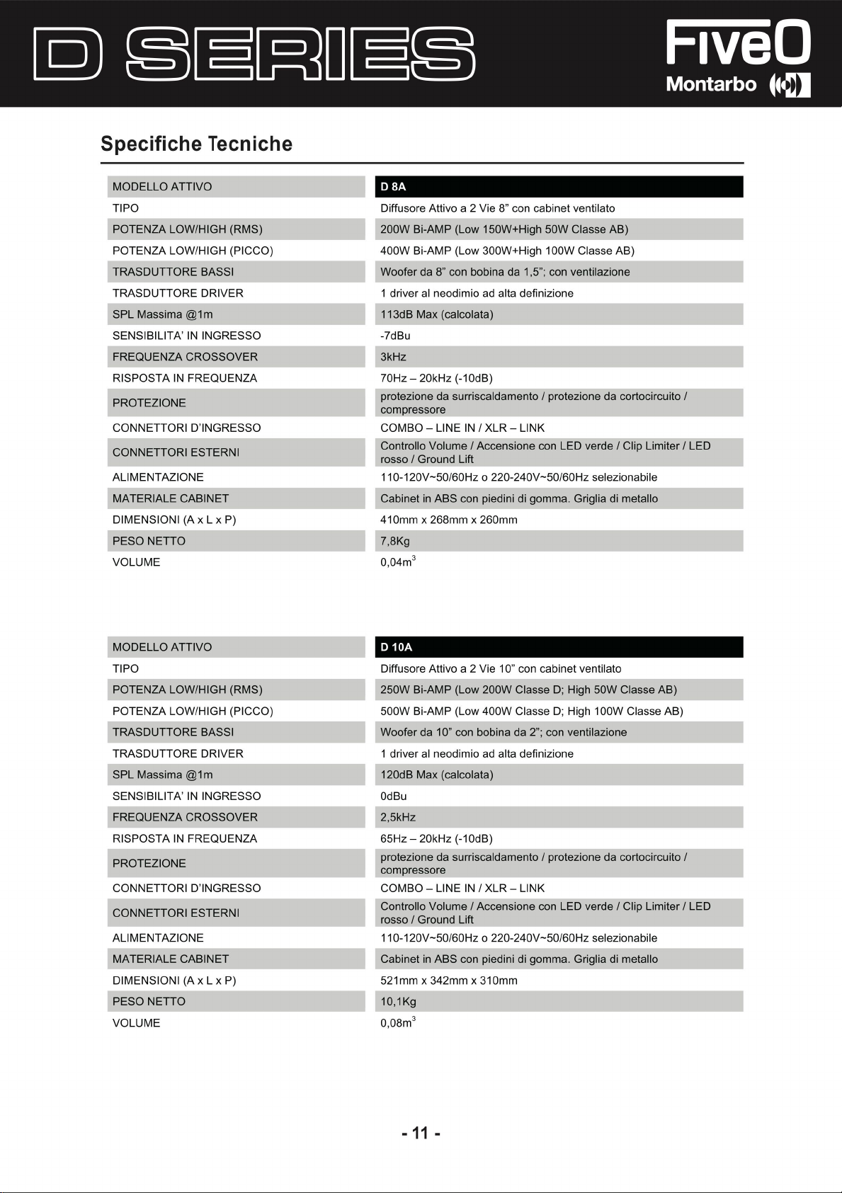
Specifiche Tecniche
MODELLO ATTIV
TIP
O
POTEN
ZA LOW/HIGH (RMS
POTENZA LOW/HIGH (PICCO
TRASDUTTORE BASSI
TRASDUTTORE DRIVE
SPL Massima @1m
SENSIBILITA' IN INGRESSO
FREQUEN
RISPOSTA IN FREQUENZ
PROTEZION
CONNETTORI D'INGRESS
CONNETTORI ESTERN
ALIMENTAZION
MATERIALE CABIN
DIMENSIONI (A x Lx P)
PESO NETTO
VOLUM
E
O
R
ZA CROSSOVER
A
E
O
I
E
ET
Diffusore Attivo
)
)
200W Bi-AMP (Low 150W+High 50W Classe AB)
400W Bi-AMP (Low 300W+High 100W Classe AB)
Woofer
1 driver al neodimio ad alt
113dB Max (calcolata)
-7dB
u
3kH
z
70Hz - 20kHz (-10dB
protezione da surriscaldamento I protezio
compressor
COMBO - LINE IN/ XLR - LINK
Controllo Volume/ Accensione co
rosso I Ground Li
110-120V-50/60Hz o 220-240V-50/60Hz selezionabil
Cabine! in A
410mm x 268mm x 260mm
7,8Kg
3
0,04m
a 2 Vie 8" con cabine! ventilato
da 8" con bobi
e
BS co
na da 1,5"; con ventilazion
a d
efinizione
)
ft
n piedini di gomma. Griglia di metall
e
ne
da cortocircuito
n LED verde/ Clip Limiter / LE
I
e
o
D
MODELLO ATTIV
TIP
O
POTEN
ZA LOW/HIGH (RMS
POTENZA LOW/HIGH (PICCO
TRASDUTTORE BASSI
TRASDUTTORE DRIVE
SPL Massima @1
SENSIBILITA' IN INGRESS
FREQUEN
RISPOSTA IN FREQUENZ
PROTEZION
CONNETTORI D'INGRESS
CONNETTORI ESTERN
ALIMENTAZION
MATERIALE CABIN
DIMENSIONI (A x Lx P)
PESO NETTO
VOLUM
E
O
R
m
ZA CROSSOVE
E
I
E
ET
O
R
A
O
D 10
A
Diffusore Attivo
)
)
250W Bi-AMP (Low 200W Classe D; High 50W Classe AB)
500W Bi-AMP (Low 400W Classe D; High 100W Classe AB)
Woofer
1 driver al neodimio ad alta d
120dB Max (calcolata)
OdB
u
2,5kH
z
65Hz - 20kHz (-10dB
protezione da surriscaldamento / protezione
compressor
COMBO - LINE IN/ XLR - LINK
Controllo Volume/ Accensio
rosso I Ground Li
110-120V-50/60Hz o 220-240V-50/60Hz selezionabil
Cabine! in A
521mm x 342mm x 310mm
10,1Kg
3
0,08m
a 2 Vie 1 O" con c
da 1 O" con bobina da 2"; con ventilazione
)
e
ft
BS co
n piedini di gomma. Griglia di metall
a bi net ventilat
efinizione
ne co
n LED verde/ Clip Limiter / LE
o
da cortocircuito
I
D
e
o
- 11
-

Specifiche Tecnich
MODELLO ATTIV
TIP
O
POTENZA LOW/HIGH (RMS
POTENZA LOW/HIGH (PICCO)
TRASDUTTORE BASSI
TRASDUTTORE DRIVE
SPL Massima @1m
SENSIBILITA' IN INGRESS
FREQUEN
RISPO
STA IN FREQUENZ
PROTEZION
LETTORE USB OPZIONAL
CONNETTORI D'INGR
CONNETTORI ESTERN
AUMEN
TAZIONE
MATERIALE CABIN
DIMENSION
PESO NETTO
VOLUM
E
O
R
ZA CROSSOVER
A
E
E
ESS
I
ET
I
(
A
x
Lx P)
)
O
O
e
D 12
A
Diffusore Attivo
500W Bi-AMP (Low 400W Classe D; High 100W Classe AB
1000W Bi-AMP (Low 800W Classe D; High 200W Classe AB)
Woofer
1 driver exit - 1 driver a compressione
122dB Max (calcolata)
OdB
u
1,8kH
z
60Hz - 20kHz (-10dB)
protezione da surriscaldamento / protezione
compressor
CON USB E Micro SD CARD, Bluetoot
INPUT1-Mi
presa jack da 6,3
Input 1&2 e Controllo Maste
Accensione con LED verde/ Clip Limiter con LED rosso/ Ground Lift/
Prese! DSP
110-120V-50/60Hz o 220-240V-50/60Hz selezionabil
Cabine! in A
618mm x 430mm x 350mm
17,1Kg
3
0,13m
a 2 Vie 12" con cabine! ventilat
da 12" con bobin
e
c con XLR e presa jack
BS con piedini di gomma. Griglia di metall
a da 2"; con ventilazion
e d
a 3,5
r Volume/ EQ a 2 bande High-Low /
da 1,4
h
da 6,3 / INPUT2-Line con XLR
o
e
"
da cortocircuito
e
o
)
I
e
MODELLO ATTIV
TIP
O
POTENZA LOW/HIGH (RMS
POTENZA LOW/HIGH (PICCO)
TRASDUTTORE BASSI
TRASDUTTORE DRIVE
SPL Massima @1m
SENSIBIUTA' IN INGRESSO
FREQUEN
RISPO
STA IN FREQUENZ
PROTEZION
LETTORE USB OPZIONAL
CONNETTORI D'INGR
CONNETTORI ESTERN
AUMEN
TAZIONE
MATERIALE CABIN
DIMENSIONI (A x Lx
PESO NETTO
VOLUM
E
O
R
ZA CROSSOVER
A
E
E
ESS
I
ET
P)
)
O
D 15
A
Diffusore Attivo
500W Bi-AMP (Low 400W Classe D; High 100W Classe AB)
1000W Bi-AMP (Low 800W Classe D; Hig
Woofer
1 driver exit - 1 driver a compressione
123dB Max (calcolata)
-6dB
u
2,2kH
z
50Hz - 20kHz (-10dB)
protezione da surriscaldamento / protezione da cortocircuito
compressor
CON USB E Micro SD CARD, Bluetoot
INPUT1-Mi
presa jack da 6,3
Input 1&2 e Controllo Master Volume/ EQ a 2 bande High-Low /
Accensione con LED verde/ Clip Limiter con LED rosso/ Ground Lift/
Prese! DSP
110-120V-50/60Hz o 220-240V-50/60Hz selezionabil
Cabine! in A
700mm x 480mm x 380mm
19,0K
g
3
0,18m
a 2 Vie 15" con cabine! ventilat
h 200W Classe AB)
da 15" con bobin
e
c con XLR e presa jack
BS con piedini di gomma. Griglia di metallo
a da 2"; con ventilazion
e d
a 3,5
da 1,4
"
h
da 6,3 / INPUT2-Line con XLR
o
e
I
e
e
- 12
-

Specifiche Tecnich
e
MODELLO ATTIV
TIP
O
POTEN
ZA (PROGRAMMA)
POTENZA (PICCO
TRASDUTTORE BASSI
SPL Massima @1m
LIVELLO DI INGRESSO
CROSSOVER ATTIV
RISPOSTA IN FREQUENZA
PROTEZION
CONNETTORI D'INGR
CONNETTORI ESTERN
ALIMENTAZIONE
MATERIALE CABINET
DIMENSIONI (A x Lx
PESO NETTO
VOLUM
E
O
)
O
E
ESS
I
P)
O
D 12A S
UB
Subwoofer Attivo 12"
600
W
1200W
Woofer
da 12" con bobina da 3"; con ventilazion
123dB Max (calcolata)
L-R UNE Input -20dBu
HPF 80 HZ co
45Hz - 160kHz (-1 OdB
protezione da surriscaldamento I protezion
compressor
L-R(COMBO/XLR-F) / L-R LINK(2-XLR-M) / Uscita L-R (2-XLR-M)
bilanciato (15k Ohm
Controllo Volume/ Accensio
rosso I Groun
110-120V-50/60Hz o 220-240V-50/60Hz selezionabil
Cabine! in MDF verniciato. Griglia di protezione ner
450mm x 430mm x 460m
24,3K
0,16m
n processore analogico
e
d Lift/ Inversio
g
3
)
)
ne con LED verde / Clip Limiter / LED
ne di fase I Bypass HPF 80Hz
m
e
e da cortocircuito
e
a di metall
/
o
MODELLO ATTIV
TIP
O
POTEN
ZA (PROGRAMMA)
POTENZA (PICCO
TRASDUTTORE BASSI
SPL Massima @1m
LIVELLO DI INGRESSO
CROSSOVER ATTIV
RISPOSTA IN FREQUENZA
PROTEZION
CONNETTORI D'INGR
CONNETTORI ESTERN
ALIMENTAZIONE
MATERIALE CABINE
DIMENSIONI (A x Lx
PESO NETTO
VOLUM
E
O
)
O
E
ESS
I
T
P)
O
D 15A S
UB
Subwoofer Attivo 15"
600
W
1200W
Woofer
da 15" con bobina da 3"; con ventilazion
124dB Max (calcolata)
L-R UNE lnput-17dBu
HPF 80 HZ co
40Hz - 150kHz (-10dB)
protezione da surriscaldamento I protezione
compressor
L-R(COMBO/XLR-F) / L-R LINK(2-XLR-M) / Uscita L-R (2-XLR-M)
bilanciato (15k Ohm
Controllo Volume/ Accensione con LED verde / Clip Limiter / LE
rosso I Ground Lift/ Inversione di fase I Bypass HPF 80Hz
110-120V-50/60Hz o 220-240V-50/60Hz selezionabile
Cabine! in MDF verniciato. Griglia di protezione nera di metallo
520mm x 480mm x 564m
29,3K
0,24m
n processore analogico
e
)
m
g
3
e
da cortocircuito
/
D
- 13
-

Specifiche Tecniche
MODEL
LO ATTIV
TIP
O
POTENZA (PROGRAMMA
POTENZA {PICCO)
TRASDUTTORE BASS
SPL Massi
LIVE
LLO DI INGRESS
CROSSOVER ATTIV
RISPOSTA IN FREQUENZA
PROTEZION
C
ONNETTORI D'INGRESSO
C
ONNETTORI ESTERN
ALIMENTAZIONE
MATERIALE CABINE
DIMENSIONI (A x Lx P)
PESO NETT
VOLUM
E
ma @1
E
O
O
)
I
m
O
O
I
T
O 18ASUB
Subwoofer Attivo 18
1000W
2000
W
Woofer da 18" con bobina da 3"; con ventilazio
128dB Max (calcolata
L-R LINE lnput-17dB
HPF 80 HZ con processore analogic
35Hz-150Hz (-10dB)
protezion
compressore
L-R(COMBO/XLR-F) / L-R LINK(2-XLR-M) / Uscita L-R (2-XLR-M
bilanciato (15k Ohm)
Controllo Volume/ Accensione con LED verde/ Clip Limiter / LE
rosso/ Ground Lift/ Inversione di fase/ Bypass HPF 80H
110-120V-50/60Hz o 220-240V-50/60Hz selezionabil
Cabine! in MDF verniciato. Griglia di protezione ner
625mm x 520mm x 580mm
33,6K
0,33m
e da surriscaldamento/ protezione
g
3
"
ne
)
u
o
da cortocircuito
a di metall
/
z
e
o
)
D
- 14
-

- 15
-

I
T
L
e informazioni contenute in quest
redatte e controllate. Tuttavia non si assume alcuna responsab
o manuale sono state attentamente
ilità pe
r
eventuali inesattezze. Questo manuale non può contenere una risposta a
tutti
i singoli problemi c
l'uso de/l'apparecchio. Siamo a vostra disposizione per fornirvi eventua
ulterior
i informazioni e consigli. Elettronica Montarbo srl non può e
ritenuta responsabile per danni o incidenti a cose o persone, causati
connessi a/l'uti
liz
zo o malfunzionamento de/l'apparecchio.
he possono presentarsi durante l'installazione
ssere
e
li
o
Elettronica Montarbo srl Via O. Pigini, 8 - 62010 Montelupone (MC) - ITALIA - T +
F + 39 0733 227 250 - mail@fiveo.it - Società controllata da Eko Music Group Spa
39 0733 227
1
NF04838-1.
2
 Loading...