

Page 1
RESOPHONIC AND NATIONAL® BISCUIT
INSTALLATION GUIDE
www.fishman.com
Read Me First!
Installation of this product is a simple procedure,
but we recommend this job only if you are an
experienced repair technician.
Requirements
The Resophonic guitar pickup is suitable for
installation on most single cone resonator guitars
with biscuit or spider cones.
The National® Style Resophonic guitar pickup is
suitable for single cone National® brand biscuit
bridge assemblies only.
Installation
Observe the following
precaution!
• Handle the pickup carefully! Mishandling
may damage the pickup, producing ground
hum or intermittent signal.
Resophonic pickup installation
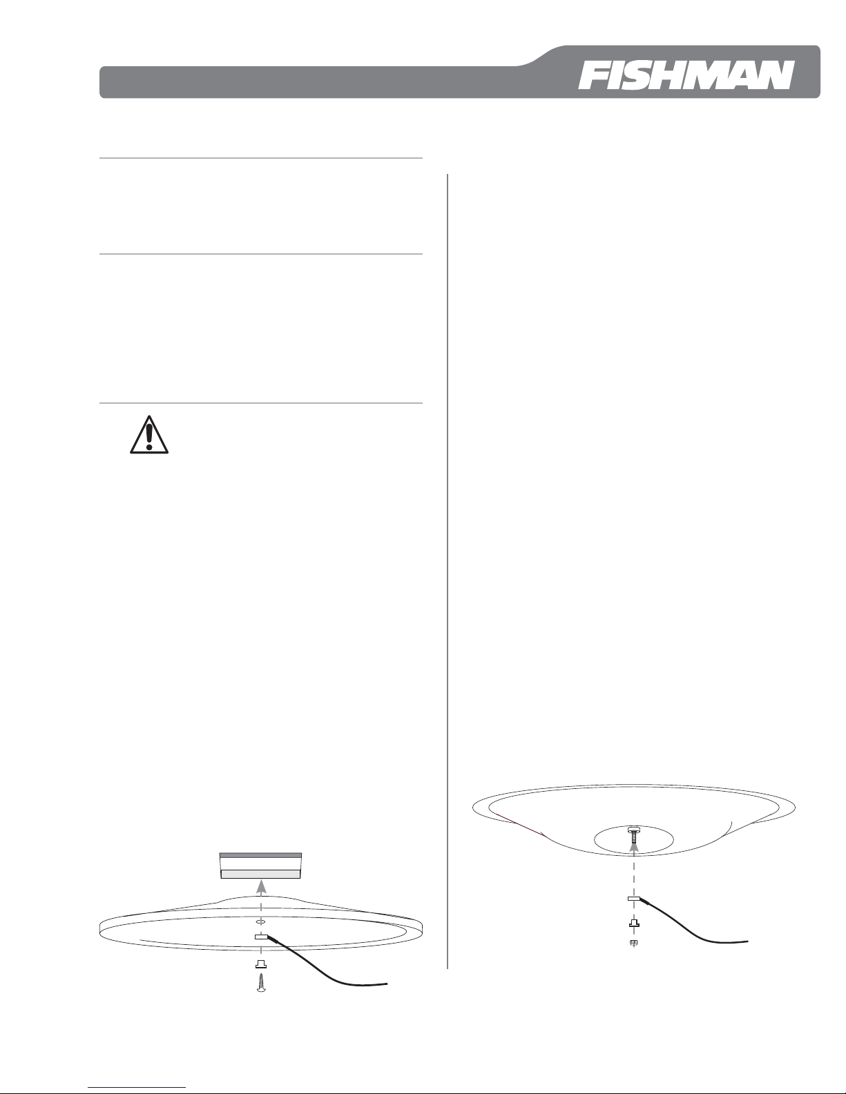
Installation for biscuit style instruments
The pickup is held against the center of the cone
with the wood screw that normally holds the biscuit
to the cone.
1. Remove the original screw from the biscuit and
swap it with the longer wood screw that is supplied
with the kit.
2. Notice that the heat-shrink tubing on the end of
the pickup is bent to one side. Do not attempt to
unbend it! If you do so you may damage the pickup.
Position the pickup so the bend in the heat-shrink
tubing faces away from the cone.
3. Place the shoulder washer into the pickup and the
screw into the shoulder washer.
4. Fasten the pickup assembly to the cone / biscuit.
Tighten the screw until snug and then another 1⁄8
turn tighter.
Biscuit Bridge
Installation for spider style instruments
For the pickup to operate properly it is critical that
the spider and cone are preloaded with the correct
pressure.
1. Remove the strings and the plate that protects the
cone assembly. Calibrate the spider / cone pressure
by loosening the screw that holds the cone to the
spider until the screw head no longer touches the
spider frame. Tighten the screw until the head just
touches the spider and then tighten one full turn
more. The spider/cone is now preloaded for
optimum bass response without buzzes or rattles.
2. If the end of the screw is long enough to accept
the pickup and locknut, go on to the next step. If it
is not long enough you will need to replace it with a
longer screw and go back to step 1. We include
replacements for both SAE 4-40 and 3mm screws
plus matching locknuts in the hardware kit. Choose
the screw that matches the threaded slug in the
center of the cone assembly.
3. Notice that the heat-shrink tubing on the end of
the pickup is bent to one side. Do not attempt to
unbend it! If you do so you may damage the pickup.
Position the pickup so the bend in the heat-shrink
tubing faces away from the cone.
4. Place the pickup, then the shoulder washer on the
screw and start to thread the locknut. You must hold
the head of the screw stationary (with the screwdriver) as you tighten the locknut or you will change
the crucial preloaded pressure on the spider and
cone. If the screw accidentally turns as you tighten
the locknut, then you must go back to step #1 and
re-calibrate the cone and spider.
5. Tighten the nut until it is snug against the pickup
and then 1⁄8 turn tighter.
6. When the installation is completed, plug the instrument into an amplifi er and slowly turn the screw
counter-clockwise until you hear the strongest signal.
Cone
Machine
Screw
Pickup
Shoulder Washer
Screw
Cone
Pickup
Shoulder Washer
Locknut
1
Page 2
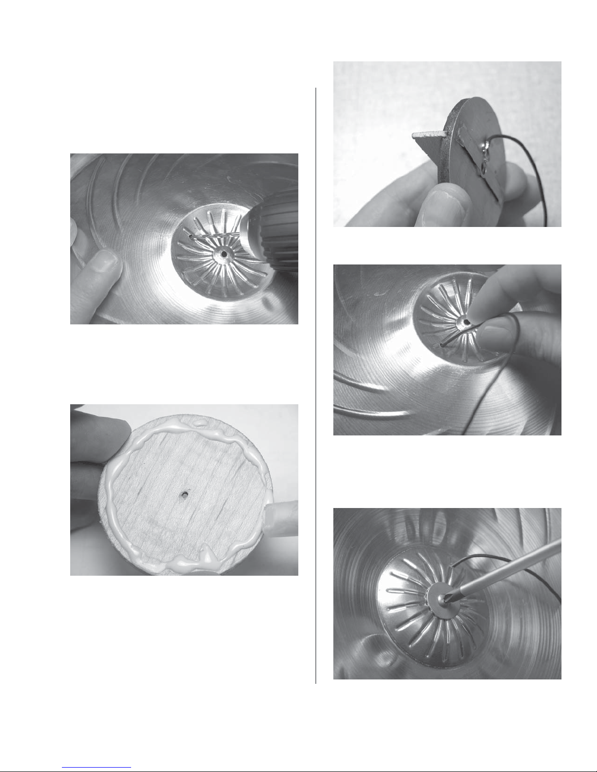
National® Style Resophonic pickup
installation
1. Remove the strings and the cover plate. Unscrew
the biscuit from the cone.
2. Drill a .094” (2.4mm) hole in the cupped side of
the cone, about 3⁄8” (9.5mm) below the rim. Remove
any burrs from the hole.
3. Examine the bottom surface of the biscuit with a
straightedge. If the biscuit is warped sand it fl at.
4. Clean off any dust or debris from the bottom of
the biscuit and apply a thin bead of woodworking
glue around the edge.
7. Thread the pickup wire through the hole you
drilled earlier.
5. Line up the ends of the saddle with the notches in
the brass disc, on the side of the disc opposite the
pickup element.
6. Affi x the biscuit to the disc and wipe off any
excess glue. Double-check the alignment between
the notches in the disc and the ends of the saddle.
Clamp for several minutes.
8. Fasten the biscuit/pickup assembly to the cone.
Tighten this screw just enough to prevent the biscuit
assembly from freely rotating on top of the cone. Do
not over tighten the screw or you may short out the
pickup!
9. Remove the barrel from the jack and thread the
pickup wire through it.
2
Page 3

Wiring Options
Passive pickup
Solder the center wire to the Tip terminal and
the shield wire to the Sleeve terminal. Fasten the
shielding cap to the jack.
Pickup Signal
to Tip
Shield to
Sleeve
Active pickup
Thread the pickup wire through the strain relief hole
at the end of the circuit board. Solder the signal wire
to the “IN” pad and the shield wire to the “G” pad.
Be careful not to burn the solder pads! If the pads
are overheated, they may lift off the circuit board.
Fasten the shielding cap to the jack.
Pickup Shield
to Ground (“G”)
G
+
PJ FISHMAN
REV. 2.3
IN
-
Pickup Signal
to “IN”
R
Jack Installation
Where to locate jack
Metal body instrument
For a metal instrument with a stick that runs the
length of the body into the tailblock, we recommend
that you place the jack on the treble side lower bout.
Use a center punch at the chosen location and use
a sharp
use a drill press and clamp the instrument securely
to prevent the drill from wandering or distorting the
shape of the hole.
3
⁄8” (9.5mm) brad-point drill. For best results,
Wooden body instrument
For most wooden instruments, locate the jack at the
endblock, centered below the tailpiece. Drill a 3⁄16”
(4.8mm) hole and enlarge it to
15
⁄32” tapered reamer. Note that if the instrument
15
⁄32” (12mm) with a
has a ring (“soundwell”) inside the sound chamber,
you may have to drill through it to accommodate
the jack.
23
1
1. 15⁄32” Nut; 2. 15⁄32” Washer; 3. 15⁄32” Star Washer;
4. Guitar Endblock; 5.
3
⁄8” Dress Washer; 6. 3⁄8” Nut
456
Battery Installation
You may locate the battery bag on any fl at surface
inside the instrument.
1. Clean the area where you will mount the bag with
mineral spirits. Let the area dry before continuing.
2. Peel off the plastic fi lm from the Velcro patch and
attach the bag at the chosen location.
3. Carefully separate the bag from the Velcro patch.
To set the adhesive, burnish the entire area of the
patch, especially the edges.
4. Install a 9V alkaline or lithium battery. Tuck the
battery into the bag and re-attach to the Velcro
patch. The adhesive under the Velcro patch requires
24 hours to achieve a full bond, so take care to not
stress the adhesive if you remove the battery bag
after the initial installation.
Complete the Installation
1. 3⁄8” Nut; 2. 3⁄8” Star Washer;
3. Guitar Body; 4.
Washer; 5.
3
⁄8” Nut
3
⁄8” Dress
23 4 51
www.fi shman.com
Reassemble the instrument and tune to pitch.
514-300-117 Rev A 5-09
 Loading...