

Page 1
ELLIPSE AURA
INSTALLATION GUIDE
www.fishman.com
Read Me First!
Installation of this product is a simple procedure,
but we recommend this job only if you are an
experienced repair technician.
Requirements
Saddle slot:
Minimum saddle slot length: 2.775” (70.48mm)
Maximum E to E string spacing at saddle: 2.5”
(63.5mm)
Soundhole
Minimum usable soundhole diameter: 3.875” (98 mm)
Maximum usable soundhole diameter: 4.125” (107 mm)
Maximum X brace height at soundhole: .5” (13mm)
The Ellipse Aura preamp is designed to fi t in
most fl at top guitars without modifi cation, but we
cannot guarantee a drop-in fi t with all instruments.
Before you begin installation, pre-fi t the preamp in
the soundhole. Ideally, the preamp should lie fl at,
with the mounting bracket fl ush to the edge of the
soundhole.
Installation
Attention: Observe precautions for
handling electrostatic sensitive devices!
Install this product only in a static-free work area.
The electronics in this preamp are sensitive to
electrostatic discharge (ESD), also known as static
shock. Even a small static shock during installation
can damage the preamp. Please read and follow
the guidelines below to ensure the preamp is
adequately protected from ESD during installation.
• Wear a grounding strap (connected to a
grounded source) during installation.
• Keep this product in its anti-static packaging
until it is installed.
• Handle the product only by the non-metallic
edges. Avoid touching any of the components on the circuit board.
Once installed in the guitar, the preamp is
adequately protected from ESD.
Other precautions
• Do not short the battery leads or allow
them to contact the circuit board during
installation or Image upload.
• Do not allow the endpin jack to contact
the circuit board during installation or
Image upload.
• Attach the battery to the battery leads only
after installation is completed.
• When separating the mounting bracket from
the preamp do not pry up the ends of the
bracket (at the magnets) or you will damage
it. See instructions below for separating the
preamp from the mounting bracket.
Preliminary
1. Widen the endpin hole to 15⁄32” (11.9mm) to
accommodate the endpin jack.
2. Drill a 3⁄32” hole (2.4mm) in the saddle slot for
the pickup wire, no less than .100” (2.5mm) from
nearest string. Install the pickup per Acoustic Matrix
installation instructions.
1. Seal the mounting surface
To ensure a strong and reliable bond,
you must now sand, clean and seal the
underside of the soundhole where the
preamp will mount.
1. Sand the underside of the soundhole down to
bare wood. Take care to remove all residual lacquer,
polish and dirt.
2. Use mineral spirits to clean the sanded area.
Remove any excess oil, resin and dust from the
exposed wood. Let the area dry before proceeding
to the next step.
3. Seal the exposed wood with an appropriate coating.
Use only a coating that will bond the
wood fi bers and present a hard, uniform
surface for the adhesive.
We recommend any of the following:
• Hide glue
• All purpose two-part epoxy
• Cyanoacrylate glue (higher viscosity,
non-instant type).
• Carpenter’s glue
Let the area dry before proceeding to the next step.
1
Page 2
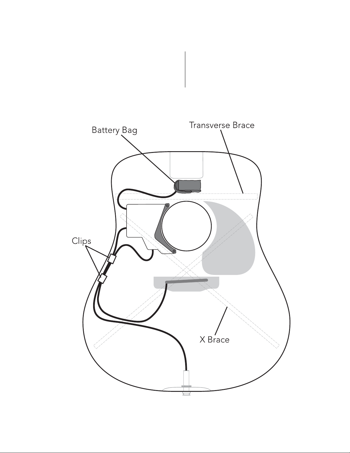
2. Test for fi t
Before exposing the adhesive, test the preamp for
fi t. Locate the module fl ush with the edge of the
soundhole, on the bass side. Center it between the
transverse brace and the bass-side X brace (fi gure 1).
If viewed as a clock face (neck at twelve o’clock), you
will position the phase switch at nine o’clock.
3. Endpin jack
Install the endpin jack per Switchjack Installation
Guide.
Figure 1. Component locations
2
Page 3

4. Fasten the pickup wires to the terminal
block on the preamp module (fi gure 2). The signal
wire goes to the terminal marked “IN,” and the
shield wire goes to the “GND” terminal. Tighten the
screws on the terminal block to secure the wires.
IN GND
Figure 3. Separate preamp
from bracket
Figure 2. Fasten the pickup wires
5. Fasten the preamp
If the mounting bracket it is not already attached
to the preamp, snap it in place now. Peel back the
release fi lm on the bottom of the mounting bracket
and fasten the preamp to the underside of the
soundhole. Apply even, steady pressure to the
preamp to set the adhesive. The adhesive gains
maximum hold after 24 hours.
6. Option: Separate the preamp from the
mounting bracket
Once the preamp is installed, you may separate it
from the mounting bracket for better access inside
the guitar. You’ll need a heavy guitar pick to separate the two. Lodge the pick between the preamp
and mounting bracket (fi gure 3) and twist until the
preamp snaps away. Swing the preamp toward the
soundhole, then separate it from the mounting
bracket (fi gure 4).
7. Secure the wires inside the instrument with
the supplied adhesive-backed clips (fi gure 1). Clean
the area where you will mount the clips with mineral
spirits. Let the area dry before continuing.
Figure 4. Release right side magnet
8. Battery bag
Install the battery bag on or near the neck block.
1. Clean the area where you will mount the bag with
mineral spirits. Let the area dry before continuing.
2. Peel off the plastic fi lm from the Velcro patch and
attach the bag at the chosen location.
3. Carefully separate the bag from the Velcro patch.
To set the adhesive, burnish the entire area of the
patch, especially the edges.
4. Install a 9V alkaline or lithium battery. Tuck the
battery into the bag and re-attach to the Velcro
patch. The adhesive under the Velcro patch requires
24 hours to achieve a full bond, so take care to not
stress the adhesive if you remove the battery bag
after the initial installation.
3
Page 4

9. Upload Images
Install the included Aura Image Gallery software on
your computer. Connect the included “mini-B” USB
cable between the Ellipse Aura preamp and the
computer (fi gure 5). Follow the onscreen instructions
to upload Images.
Warning: If you upload Images before
installing the preamp, observe ESD handling
and other precautions outlined in the beginning
of these instructions.
Figure 5. Upload Images
from Aura Image Gallery
10. Set Input Trim
The Input Trim is located below the USB port.
Once the instrument is strung up and the battery
is installed, set the input trim as follows:
1. Move the Image switch left to #1.
2. Hold down the Measure switch as you plug in
the guitar.
3. Use a miniature jeweler’s screwdriver to gently
raise or lower the Input Trim so the Battery LED
fl ashes occasionally with hard strumming.
4. To exit the setup, unplug the guitar.
For more convenient access, remove the preamp
module from its magnetic base before you set the
Input Trim. See fi gures 3, 4 and 6.
11. Use caution when you
clean the fi ngerboard or
perform fret work!
The powerful neodymium magnets used to secure
the preamp will attract steel-wool debris and fret
fi lings. These can damage the Ellipse electronics.
As a precaution, cover the soundhole before you
work on the fi ngerboard. Uncover only after all
debris is removed.
Figure 6. Adjust trim
www.fi shman.com 514-300-001 Rev C 4-07
 Loading...