

Page 1
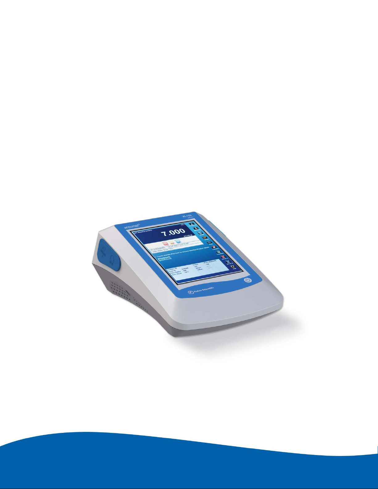
Reference Guide
Fisher Scientific
accumet
®
Excel (XL)
Benchtop Meters
XL150 ● XL200 ● XL250 ● XL500 ● XL600
68X623601 Rev 0 October 2012
1
Page 2

Table of Contents
1. INTRODUCTION ............................................................................................................................................. 4
2. TOUCH SCREEN & ICONS ............................................................................................................................... 5
3. CONNECTIONS .............................................................................................................................................. 8
4. ELECTRODE BRACKET & ARM ASSEMBLY ....................................................................................................... 9
5. POWER ON/OFF .......................................................................................................................................... 10
6. SYSTEM SETUP ............................................................................................................................................ 11
7. ADMINISTRATION & USER ID ...................................................................................................................... 12
8. PARAMETER SETUP: SAMPLE ID .................................................................................................................. 14
9. PARAMETER SETUP: AUTO READ MODE ..................................................................................................... 15
10. PARAMETER SETUP: STABILITY CRITERIA / STABLE INDICATOR ................................................................... 16
11. PARAMETER SETUP: DEFAULT TEMPERATURE ............................................................................................ 17
12. PARAMETER SETUP: ISOPOTENTIAL POINT ................................................................................................. 18
13. PARAMETER SETUP: ALARM LIMITS ............................................................................................................ 19
14. PARAMETER SETUP: PRINT CRITERIA .......................................................................................................... 20
15. PARAMETER SETUP: DATA STORAGE CRITERIA ........................................................................................... 21
16. PARAMETER SETUP: DISPLAY CRITERIA ....................................................................................................... 22
17. VIEWING & EXPORTING STORED DATA (LOG VIEW) .................................................................................... 23
18. GRAPHING .................................................................................................................................................. 24
19. STANDARDIZATION ..................................................................................................................................... 25
20. TEMPERATURE OPERATION ........................................................................................................................ 26
21. PH OPERATION............................................................................................................................................ 27
22. MILLIVOLT OPERATION ............................................................................................................................... 29
23. ION: SETUP & OPERATION .......................................................................................................................... 30
24. ION: DIRECT READING METHODS ................................................................................................................ 32
25. ION: INCREMENTAL METHODS .................................................................................................................... 34
26. ION: KNOWN ADDITION METHOD .............................................................................................................. 35
27. ION: KNOWN SUBTRACTION METHOD ........................................................................................................ 36
28. ION: ANALATE ADDITION METHOD ............................................................................................................. 37
29. ION: ANALATE SUBTRACTION METHOD ...................................................................................................... 38
30. CONDUCTIVITY / RESISTIVITY OPERATION .................................................................................................. 39
31. TDS OPERATION .......................................................................................................................................... 41
32. SALINITY OPERATION .................................................................................................................................. 42
33. DISSOLVED OXYGEN OPERATION ................................................................................................................ 43
34. BOD OPERATION ......................................................................................................................................... 48
2
Page 3

35. OUR OPERATION ......................................................................................................................................... 49
36. SOUR OPERATION ....................................................................................................................................... 50
37. FIRMWARE UPGRADE ................................................................................................................................. 51
38. SPECIFICATIONS .......................................................................................................................................... 54
39. REPLACEMENTS & ACCESSORIES ................................................................................................................. 57
40. WARRANTY ................................................................................................................................................. 59
41. RETURN OF ITEMS ....................................................................................................................................... 60
42. NOTICE OF COMPLIANCE ............................................................................................................................. 61
43. DECLARATION OF CONFORMITY ................................................................................................................. 62
3
Page 4
1. INTRODUCTION
Thank you for selecting the Fisher Scientific accumet XL benchtop meter.
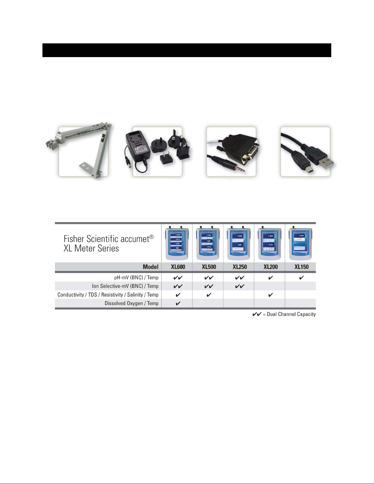
All models include an electrode arm with metal bracket (13-637-671), 110/220 universal power supply
(13-636-104), RS-2 32, and USB cable. T he electrode arm can be attached to the l eft, right, or center of
the meter according to your preference using a Phillips screwdriver. If the instrument will be wall
mounted - the electrode arm should be removed from the bracket.
13-637-671 13-636-104
Please note that this m anual serves five models, so not all secti ons of the manual are relevant to eac h
model. The chart below lists the parameters served for the various models:
Intended Use:
Fisher Scientific accumet XL150, XL200, XL250, XL500, and XL600 models are designed for
measurement and monitoring of water-based, electrochemical parameters using replaceable sensors.
Designated use of thes e instruments is exclusive ly for measurement in indoor, laboratory environm ents.
Any use above and beyond this is considered non-intended use.
4
Page 5

2. TOUCH SCREEN & ICONS
The Fish er Scientific accum et XL150 / XL200 / XL250 / X L500 / XL600 series bencht op meters operate
with a high perform ance TFT color touch screen. T he touch screen can be controlled b y a finger or an
optional USB mouse. Avoid damage to the display by preventing contact from aggressive chemicals,
solvents, hot liquids, and all sharp or pointed objects such as a screwdriver which can damage the screen.
A stylus is suitable for normal use if desirable.
The buttons on the right si de of the screen control all of the f unctions of the meter. A light touch on the
screen is all that you ne ed to acces s the various f unctions. If the beep f unction is enabled, you will get an
audible tone with each pre ss on the touch screen. Note: the screen will not change until you lift your
finger. This design prevents rapid uncontrolled scrolling through the various function screens.
Function buttons and options change from screen to screen. Easy to understand prompts guide you
through the operation of the meter in the selected mode. For a dditional details on the particular sc reen
you are viewing, select “Help” located on the bottom right corner of the display.
Your meter was shipped with a clear protective sheet to protect the LCD display and “bubbles” may
appear on the screen. The screen will respond better and visibility will improve if it is removed.
Alternatively, you may choose to leave this on for added protection.
Maintenance And Precautions:
For routine maintenance disconnect the power cord, then dust or wipe the display using a damp cloth. If
necessary, warm water or a mild water based detergent can be used. Maintenance can be performed as
required by the environment in which the meter is operated. Immediately remove any spilled substance
from contact with the meter using the proper cleaning procedure for the type of spill.
• Do not use this equipment in potentially explosive atmospheres.
• Refer to the electrode instructions for use, storage, and cleaning.
• Ensure that no liquid enters the instrument.
• Do not use any aggressive cleaning agents (solvents or similar agents).
• The instruments do not have user serviceable parts inside.
Attempts to service internal parts may void the warranty.
Here Is A List Of V arious Icons And A Summary A s To The Function Of Each:
Administration: Use to create and edit user login ID profiles, Passwords, and User Groups.
System Setup: Use to configure and view system settings. These include stirrer speed, printer, touch screen
calibration, date & time and brightness settings.
5
Page 6
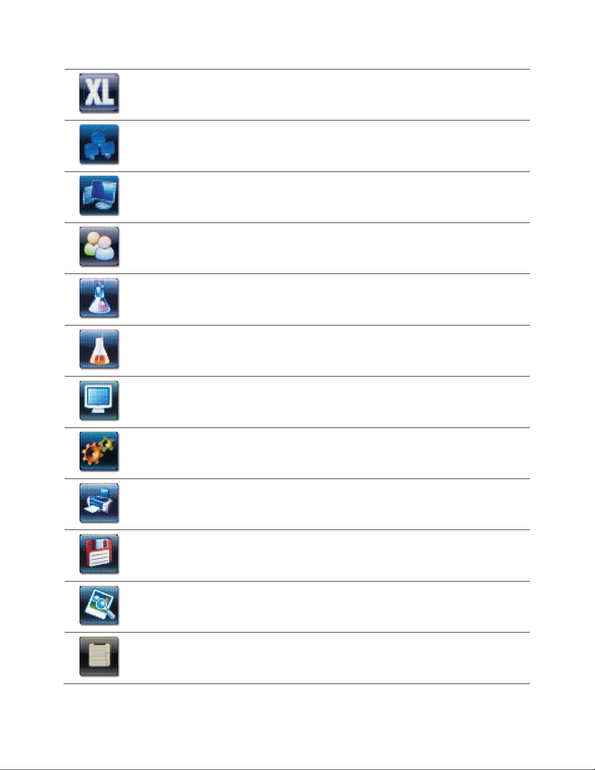
About: Provides information about the instrument such as software version and serial number.
XL150.
Single Channel: Use to display one measurement mode. Note: Single Channel is required to access the
Standardization mode, Printing function, and On-screen graphing.
Multi Channel: Use to display measurement mode of multiple channels simultaneously. Not available with
Display Setup: Use to configure the display options and select input parameters.
User: Select to view the current user profile, company name, and user group, or Log Off as the current user.
Refer to Administration icon to create or edit user login ID profiles, passwords, and user groups.
Standardize: Use to standardize (calibrate) the desired parameter. Note: Available from single-channel
measurement display only and not used for mV / relative mV offset adjustment.
Measure: Use to resume live measurement after “Auto Read” function has been activated and the
measurement is frozen. Note: not available with mV, BOD, OUR, or SOUR display.
Mode: Use to change operation modes. Also use to gain access to Administration, System Setup, About, and
Internet Explorer icons.
Setup: Use to customize changes to measurement parameter.
Print: Use to print data manually from measurement mode. If you selected the “LOG DATA” option in the
“Print Criteria” setup, clicking on the Print icon from the measurement mode will send data to the printer:
Available from single-channel measurement display only.
Log Data: Use to save the current measurement data manually to memory. Sample ID entry is required
before data can be saved (this is available from Setup).
Log View: View saved data in memory on the display.
Standardization View: View details regarding standardization (calibration) data on the display.
6
Page 7
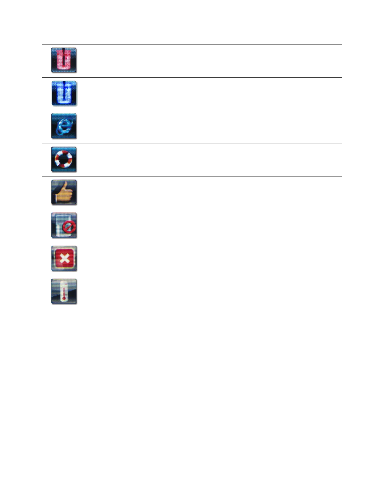
Stirrer A: Provides On/Off control of optional stirring probe (13-620-BSP) that is connected to Stirrer port A
located in rear of unit.
Stirrer B: Provides On/Off control of optional stirring probe (13-620-BSP) connected to Stirrer port B located
on the left hand side of unit.
IExplorer: Internet Explorer mobile browser for use with RJ45 port. RJ45 cable is not provided.
Note: sound and video are not enabled during browsing.
Help: Provides helpful text relevant to the display available from various screens.
Use Confirm to accept the standard value during standardization (calibration).
Use Clear to erase all of the previous standardization values for the selected parameter.
Use Cancel to abort the standardization and return to measurement without accepting the standard value.
Use to standardize (calibrate) the temperature value associated with the selected parameter.
Note: XL250, XL500,& XL600 offer multiple temperature ports that correspond to the respective BNC ports.
7
Page 8
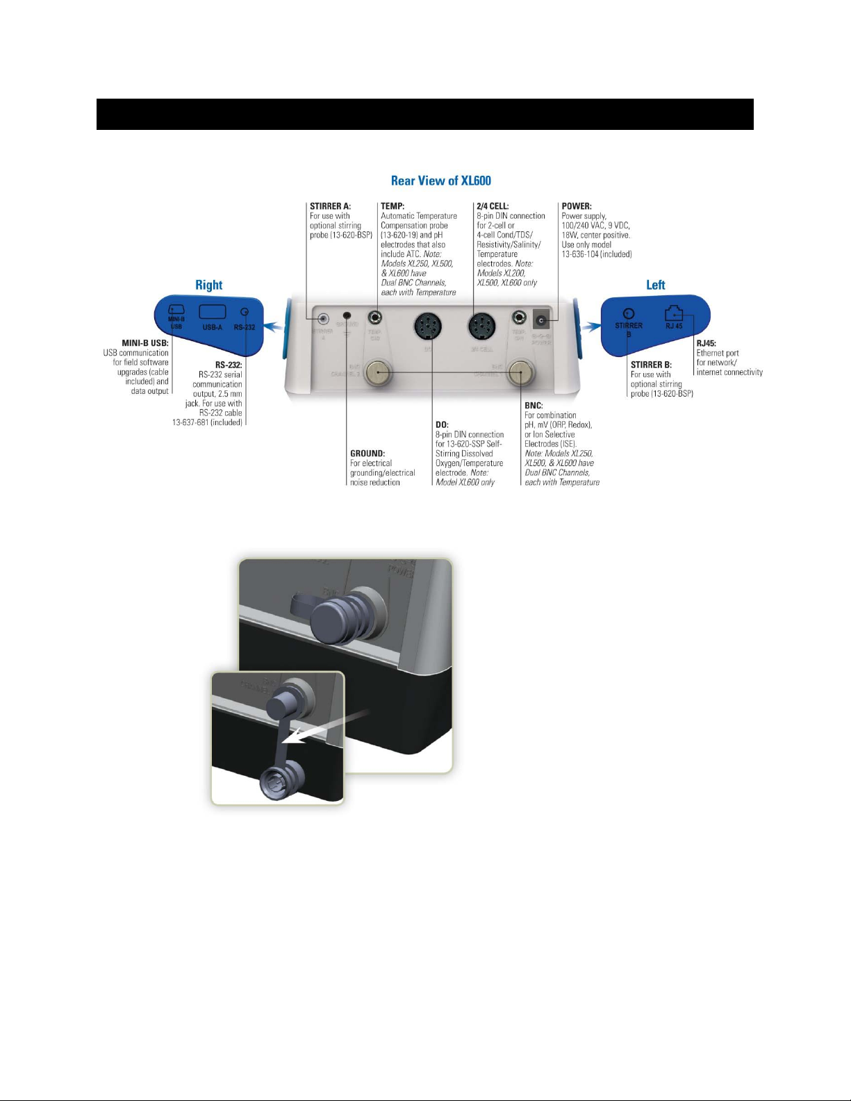
3. CONNECTIONS
Prior to attaching pH, ORP, or Ion
electrodes, the BNC shorting cap
(13-620-99) should be removed.
Do not discard the shorting cap. This cap
is useful for simulating a 0 mV signal and
also as a protective covering when the
BNC connection is not in use. A strap will
retain the cap in place when an electrode
is connected.
8
Page 9
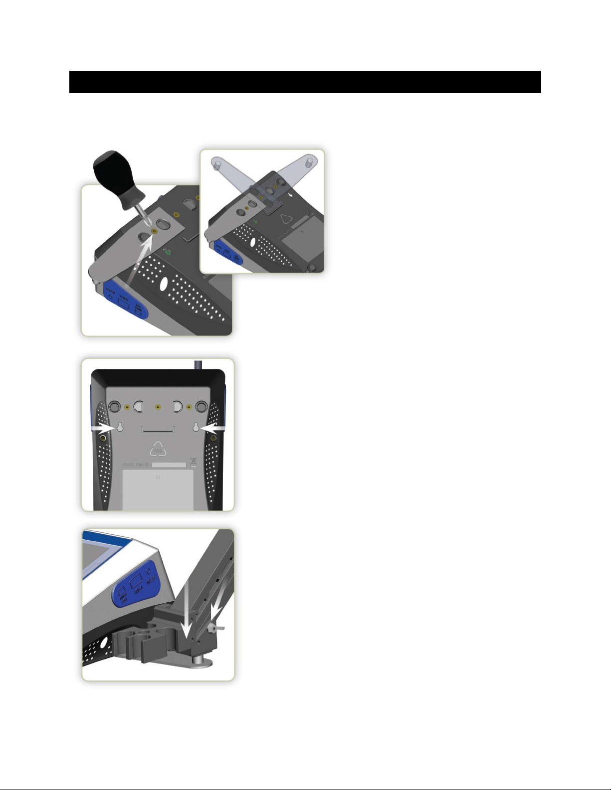
4. ELECTRODE BRACKET & ARM ASSEMBLY
Connect the metal electrode bracket to
the base of the meter using a Phillips
screwdriver. The bracket may be attached
to the left, right, or center according to
your preference.
If the instrument will be wall
mounted using the wall mount holes,
the electrode arm should be removed from
the bracket.
Attach the electrode arm to the
bracket & tighten the wing nut.
Purchase an additional arm/bracket
(13-637-671) to utilize two arms in left
& right positions simultaneously.
9
Page 10

5. POWER ON/OFF
ON: To power on the unit, press the on/off key found on the lower right hand side of the
instrument for three seconds:
As the instrument boots up , the meter will go thru a series of self-checks and dis play the model and the
current software re vision. After log in windo w, the ins trum ent will cont inue to m easurem ent m ode that was
used previously. (See
OFF: Please power off the unit when not in use to conserve energy. To power off the unit,
press the on/off k ey for three seconds. A pop-up window will ap pear; “Are you sure you want
to shutdown”. Press “OK” to pow er off the ins trument or “Cancel” if you do not w ish to power off
the instrument.
Section 7- Administration and User ID
to create additional User ID’s).
10
Page 11

Tip: Check www.fishersci.com/accumet for free instrument software updates.
6. SYSTEM SETUP
Use the System Setup to cus tomize operation of your
XL series meter.
To access System Setup, select MODE from any
measurement screen, then select the “Sys.
Setup” icon.
The following settings can be customized for each model:
• Optional 13-620-BSP Stirrer A /Stirrer B Speed
(1 = slowest to 5 = fastest).
• Brightness
• Printer Option
• RS-232 Print Format
• Beep Status: (Enable or disable a short aud ib le
tone with each selection).
• Network Printer
• Language Selection: (Select the preferred
language that is displayed on the instrument).
• Set Date and Time
• Std. Due Setting: (Set an optional reminder to alert you if a specified period of time has elapsed since
the last standardization has been performed).
• Display Color Setting: (Change the appearance of the display).
11
Page 12
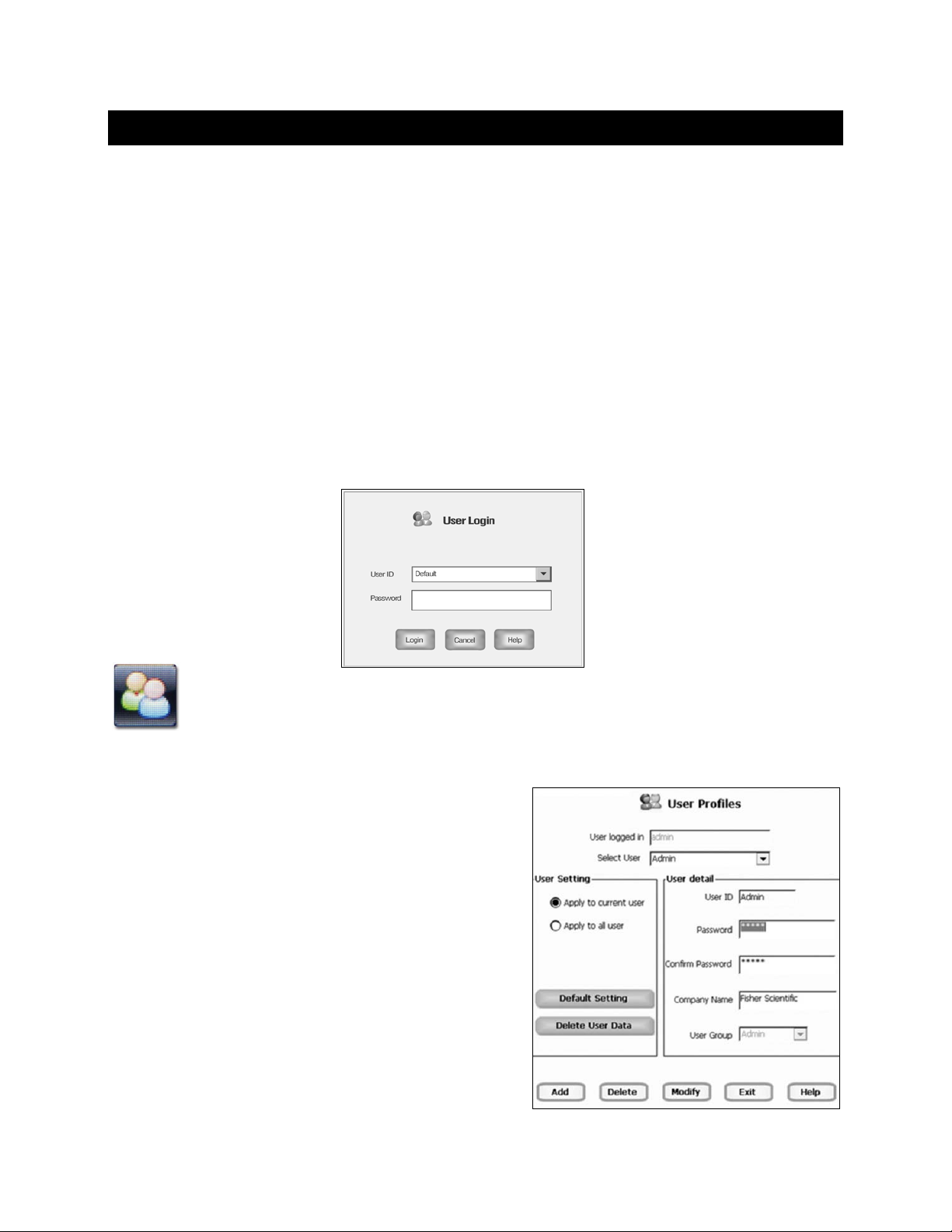
7. ADMINISTRATION & USER ID
Up to (10) unique User ID’s can be created. Alternatively, the factory default User ID login “Default”
with no password protection can be used. Creation of a User ID is optional but can offer several
advantages including:
• Security: Password protection for each User ID.
• Separation: Keep stored data, settings, & standardization together.
• Detailed Data: Saved and printed includes the unique User ID setting.
• Reduce Setup and Standardization: Instead of using “Default”, create a department or application
specific User ID, such as “LAB”, “QC”, “pH”, or “Test 123”. This will save significant setup time and also
eliminate the need for new standardizations with each parameter change.
The User Login dialog box automatically appears upon instrument start up. A User ID that has been
added will show up in the drop down menu. When using Default as the User ID, a password is not
required. The instrument will continue to the measurement mode upon a successful login.
Select the User icon to view the curren t user profile, com pany name, and user group, or Log
Off as the current user.
Administration Setup / A dding User Profiles:
1. From any measurement screen. Select “Mode” and
then select the “Admin” ico n.
2. Select the User ID text box and the alphanumeric
keypad will appear. When entering the User Profiles
setups for the first time, enter User ID = “admin” and
Password = “Admin”. Note: the password is case
sensitive – use an upperc as e A in “Admin”.
3. Update the Password and Company Name information
by tapping in the appropriate boxes, if you are logged in
as a user.
4. After logging in under User ID "admin" the User Detail
fields will show information f or "Admin". Select “Add”
to enter a new User ID. You can now begin entering
information for new users.
12
Page 13

5. Use the alphanumeric keypad to key in the new User ID. The User ID cannot exceed 10 characters.
Press Enter to confirm.
6. Use the alphanumeric keypad to key in the Password. The password cannot exceed 12 characters.
Press Enter to confirm.
7. Use the alphanumeric keypad to key in the Confirm Password field. Press Enter to confirm.
8. Use the alphanumeric keypad to key in the Compan y Name. Select OK when all changes ha ve
been made.
9. Select Add. A window wil l sho w "Are you sure, you want to add this user?" Select Yes or No.
Select Yes to add the new user. Select No to continue editing the current user.
10. Upon successful addition of a new user ID, the instrument will show “User has been added
successfully” . Select “OK”.
11. Select Exit when finished. A message “User profile saved. Meter will reboot now” will appear.
Select “OK”. The instrument will restart and the newly created User ID(s) will be available.
Function Keys From U ser Profiles Screen:
• Add: To add a new User ID.
• Delete: To delete the user ID.
• Modify: Modify the current user details.
• Exit: To exit User Profile Screen. Reboot is automatic after adding new User ID or making changes
to an existing user.
• Apply To Current User: To apply Default Setting or Delete User Data function buttons to current
user only.
• Apply To All User: To apply Default Setting or Delete User Data function buttons to all users.
• Default Setting: To reset current or all users to factory default setting of meter.
• Delete User Data: To delete all measurement data for current or all users.
13
Page 14
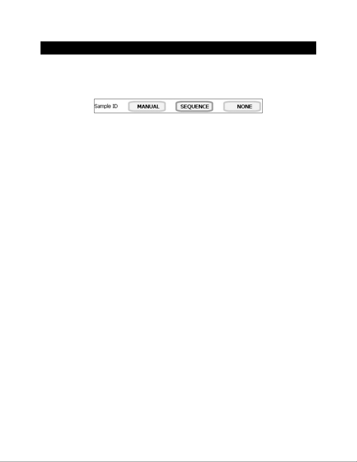
8. PARAMETER SETUP: SAMPLE ID
A Sample ID is required to log data or activate a timed printing. When Log Data is selected from the
measurement screen, the Sample ID will be associated with the measured value along and other
measurement details.
The Sample ID can be accessed by selecting Setup from the Measurement screen of any parameter.
Manual:
Use up to 10 alphanum eric characters for identific ation. When using tim ed printing, the identical Sam ple
ID will be used for all data collection.
Sequence:
Use up to 10 num bers for identificatio n. When using t imed printing or logging dat a manually, the Sample
ID is automatically increased by 1. Choose Sequence instead of Manual if unique Sample IDs
are desired.
None:
Select None to deactivate the sample ID assignment.
14
Page 15

Tip: Take caution when using AUTO; if accidentally selected, it may seem like the
9. PARAMETER SETUP: AUTO READ MODE
The Auto Read option is available from any parameter Setup. Manual is most typical and the
recommended setting. It is also the factor y default setting. Auto Read mode setting is effective only in
Single Channel display.
Auto:
When the Auto Read function is set to AUTO, the meter will freeze the measurement as soon as the
STABLE indicator appears. Once locked, the reading will not change until Measure is selected.
electrode or meter is un-responsive when in fact the measurement is locked and
selecting “Measure” screen is the only way to get the current reading to re-appear.
Manual:
When the Auto Read function is set to MANUAL, the STABLE indicator will appear, however the live
measurement will conti nue to update on the displa y. The measurement does not f reeze. The “Measure”
icon is not active during Manual setting.
Note: For ISE, if the Ion method is Known Addition, Known Subraction, Analate Addition, and Analate
Subtraction then the Auto Read f unctionalit y is inactive. The meas ure button in the meas ure button in the
Measurement screen will be replaced with Respective Ion method symbol-either; KA, KS, AA or AS.
15
Page 16
Tip: Select a lower pH resolution such as X.XX instead of
X.XXX to decrease stabilization time.
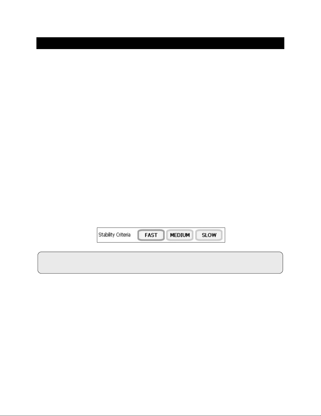
10. PARAMETER SETUP: STABILITY CRITERIA / STABLE INDICATOR
Various Stability Criteria and Stable Indicator options can be accessed from the parameter Setup:
pH: Fast / Medium / Slow
mV: None
ISE: Fast / Medium / Slow / OFF, Stable ON/OFF
Conductivity/Resistivity/TDS/Salinity: Stable ON/OFF
Adjust how quick ly and frequently the STABLE indic ator appears. T o display STABLE m ore quickly and
more often, select FAST. MEDIUM or SLOW is recommended for most applications.
FAST: The STABLE indicator will appear quickest of any setting. If you find that the indicator appears
and disappears too frequently, try a slower setting. This setting is often not suitable for use with most
non-refillable (gel filled) electrodes which are generally slower to respond.
MEDIUM: This is the factory default setting. It provides a balanced response which works best for
most applications.
SLOW: The STABLE indicator will take longer to appear and will appear less frequently. Use this setting if
you require high precision and don’t mind waiting longer to achieve this.
ON: The STABLE indicator will appear.
OFF: The STABLE indicator will not appear.
16
Page 17
Tip: Using an ATC probe will override any value entered
The measured temperature will be used by the meter to determine the pH reading.
11. PARAMETER SETUP: DEFAULT TEMPERATURE
To eliminate temperature errors associated with the pH electrode, attach an automatic temperature
compensation (ATC) probe for best accuracy. Without temperature compensation, pH accuracy will
decrease as samples deviate from 25 ºC and pH 7. The factory default setting is 25 °C / 77 °F.
If you are not using an ATC probe or the ATC is r emoved fr om the m eter, the default tem perature w ill be
used instead. The default temperature range is -10 °C to 110 °C.
If you are measuring the pH of a solution that is not 25 °C and you are not using an Automatic
Temperature Compensation (ATC) probe, enter the temperature value of the solution for best results.
The manual temper ature c ompensation (MTC) value will be visible on the screen . The default temperature
can be set from -5 °C to 105 °C.
To Set Default T emperature:
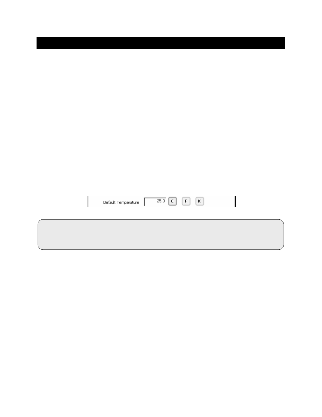
1. Select temper ature uni ts by touching the appropriate unit button: C (Celsius), F (Fahrenheit) or
K (Kelvin).
2. Touch the Default Temperature box and use the numeric keypad to enter the desired default
temperature (-5 °C to 105 °C).
3. Press Enter in the keypad to return to pH (pH FET) Setup screen.
in the default temperature screen.
17
Page 18
12. PARAMETER SETUP: ISOPOTENTIAL POINT
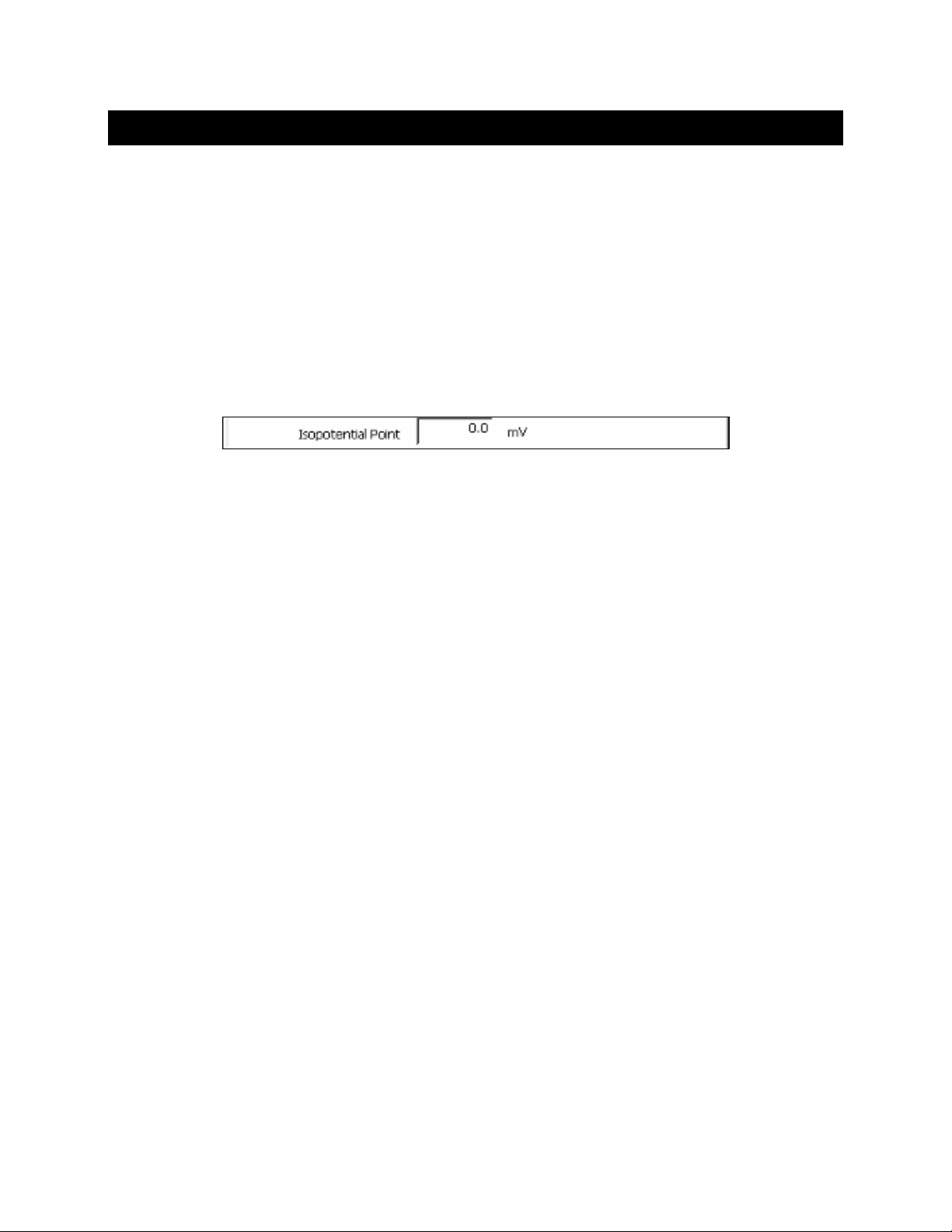
The isopotential point is the millivolt reading for an electr ode at which temperature has no effec t on the
measurement. Electrodes for pH measurement are constructed so that the isopotential point is
theoretically zero millivolts. Most pH electrodes do not achieve this value precisely. However they are
close enough so that it is not usually necessary to use an isopotential point other than zero. The true
isopotential point of an y given electrode m ust be determined experimentally. The isopotential p oint can
be set from -100 to +100.
To Set Isopotential Point:
1. Touch the Isopotential Point box and use the numeric keypad to enter the desired mV setting for the
new isopotential point.
2. Touch Enter to accept this value and return to pH (pH FET) Setup screen.
Apply Temperature Compensation (Ion Setup Only):
Ion concentration is a temperature dependent measurement. Best results are obtained when the
standards and the samples are standardized at the same temperature. However, if you have
experimentally deter mined the isopo tential point of your ion selecti ve electrode, you can choose to Apply
ATC by entering the Isopotential Point.
The Default value is NO which is satisfactory for most applications.
The Isopotential poi nt is the millivolt reading of an e lectrode at which temperature has no effect on the
measurement. Unlik e pH electrodes, Ion select ive electrodes are not des igned to achieve an y particular
isopotential point. If samples and standards are at different temperatures when performing ISE
experiments, it will be necessary to experimentally determine the isopotential point of your own Ion
Specific Electrode.
The Isopotential range is -100 mV to +100 mV.
18
Page 19

13. PARAMETER SETUP: ALARM LIMITS
The High and Low Alarm Limits are available from any parameter Setup.
Select an Alarm Limit to enab le a visual and audible alarm to alert you whenever a High or Lo w value is
exceeded. When a measurement exceeds the Alarm limit, a corresponding “HI ALARM” or “LOW
ALARM” wil l bli nk on the display
will continue until the conditions are no longer met, and will only be active during measurement mode.
To Set An Alarm Limit:
1. Select ON to enable the Alarm Limits, or OFF to disable the
Alarm Limits.
2. Select the Low window to enter or modify the Low limit
value using the keypad.
3. Select the High window to enter or modify the High limit value using the keypad.
Tip: If you want to use High or Lo w Alarm only and not both, choose the minimum (Low) or maximum
(High) value. For exam ple, if you want the alarm to notif y you when the pH reading goes abo ve 12, but
don’t want any other alar m to be active, turn Alarm Lim its ON and enter -2.00 as the Lo w va lue , and 12. 00
as the High value.
while simultaneously producing a loud, intermittent beep
. The alarm
19
Page 20
14. PARAMETER SETUP: PRINT CRITERIA
The Print Criteria setting is ava il ab le f rom an y parameter Setup. Use this op tio n to s elect whic h c riteria are
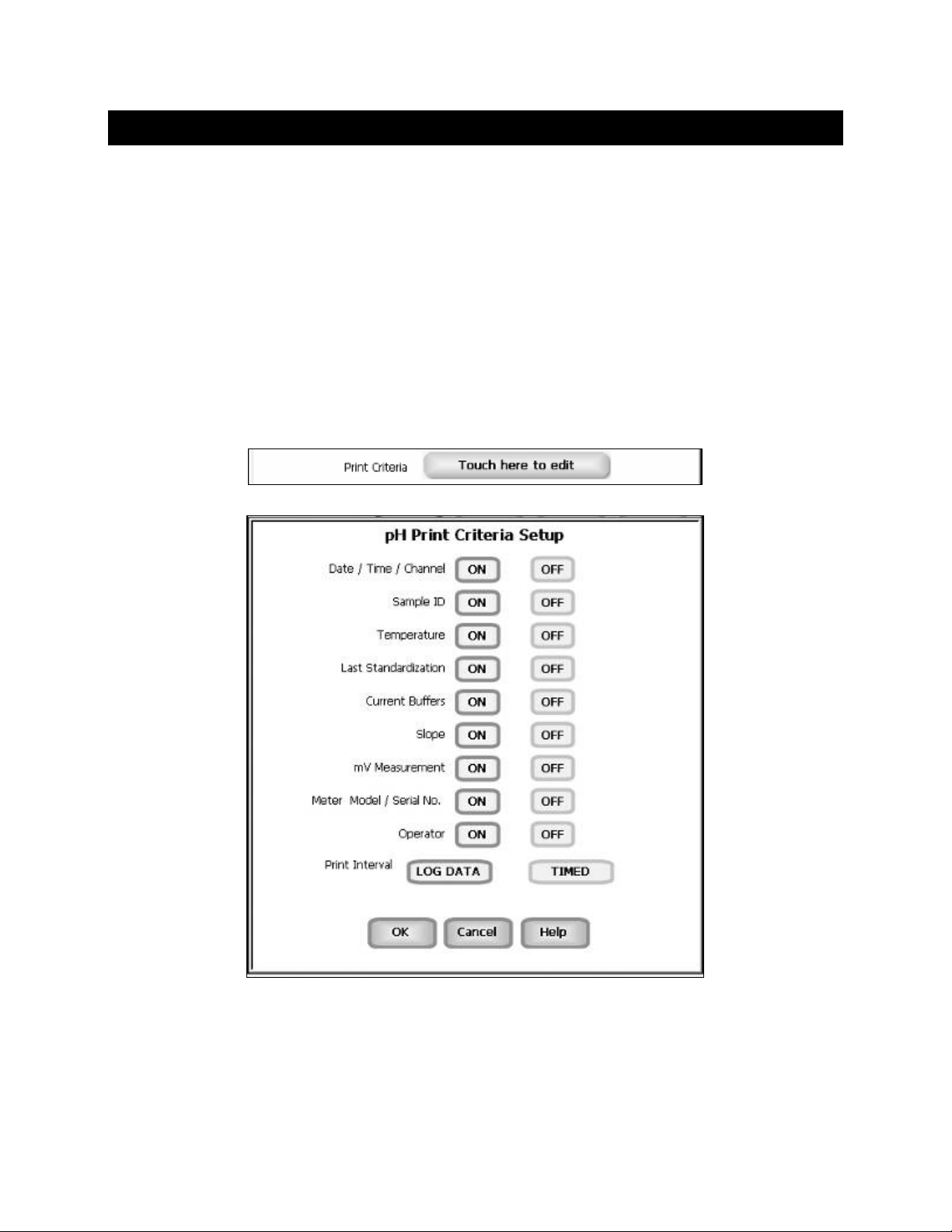
printed along with the measurement when you print the data.
To Set Print Criteria:
1. Select Touch here to edit next to Print Criteria.
2. Select ON or OFF for each detail.
3. For Print Interval select Log Data or Timed. If Log Data is selected, clicking on the “Print” button
from the Measurement screen will send the data to the printer. If Timed is selected, you can print data
at a pre-determined interval. This data is buffered and sent to the printer when the page is full.
4. Select OK to accept your selections.
20
Page 21
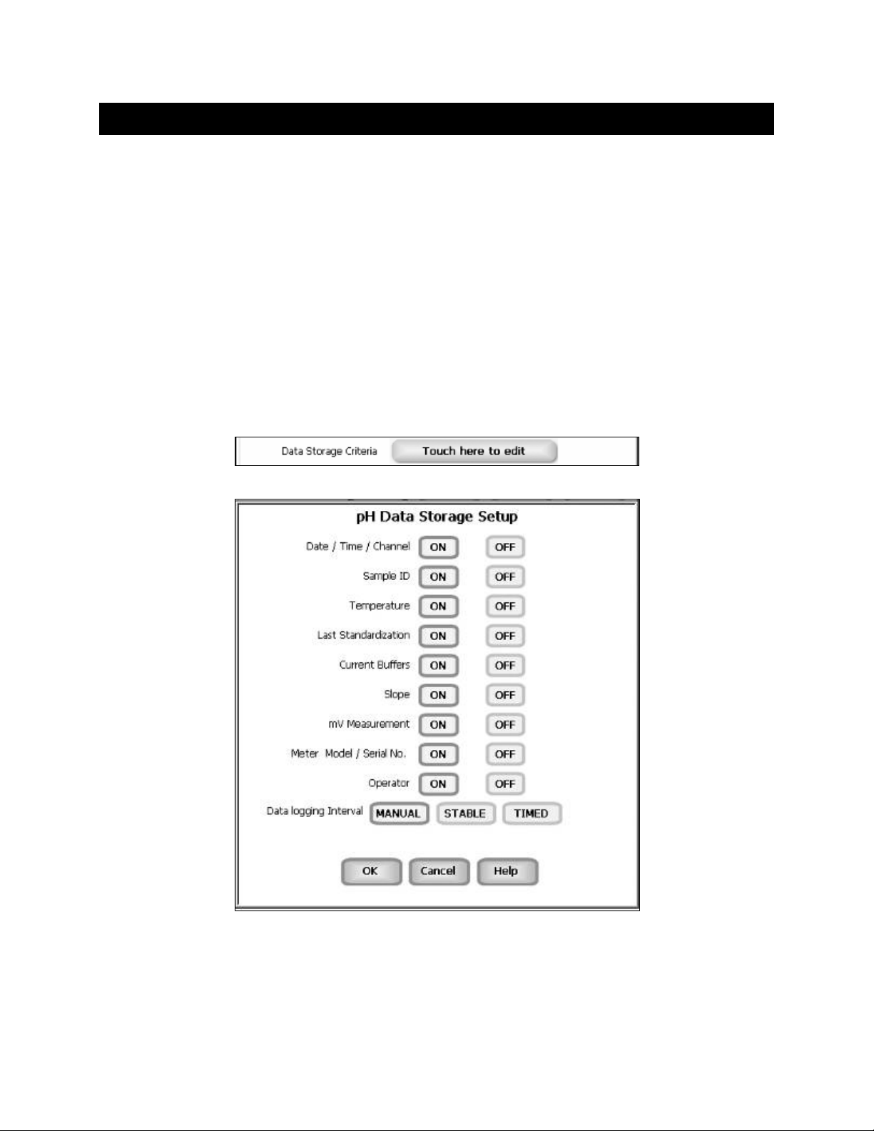
15. PARAMETER SETUP: DATA STORAGE CRITERIA
The Data Storage Criteri a setting is available from any parameter Setup. Use this option to select which
criteria to include when saving data into memory.
To Set Data Storage Criteri a:
1. Select Touch here to edit next to Data Storage Criteria.
2. Select ON or OFF for each detail.
3. For Data Logging Interval select MANUAL, STABLE, or TIMED.
MANUAL: Saves data to memory only when Log Data is pressed.
STABLE: Saves data to memory only when the STABLE indicator appears.
TIMED: Saves data to memory automatically at user determined intervals (3 sec minimum).
4. Select OK to accept your selections.
21
Page 22
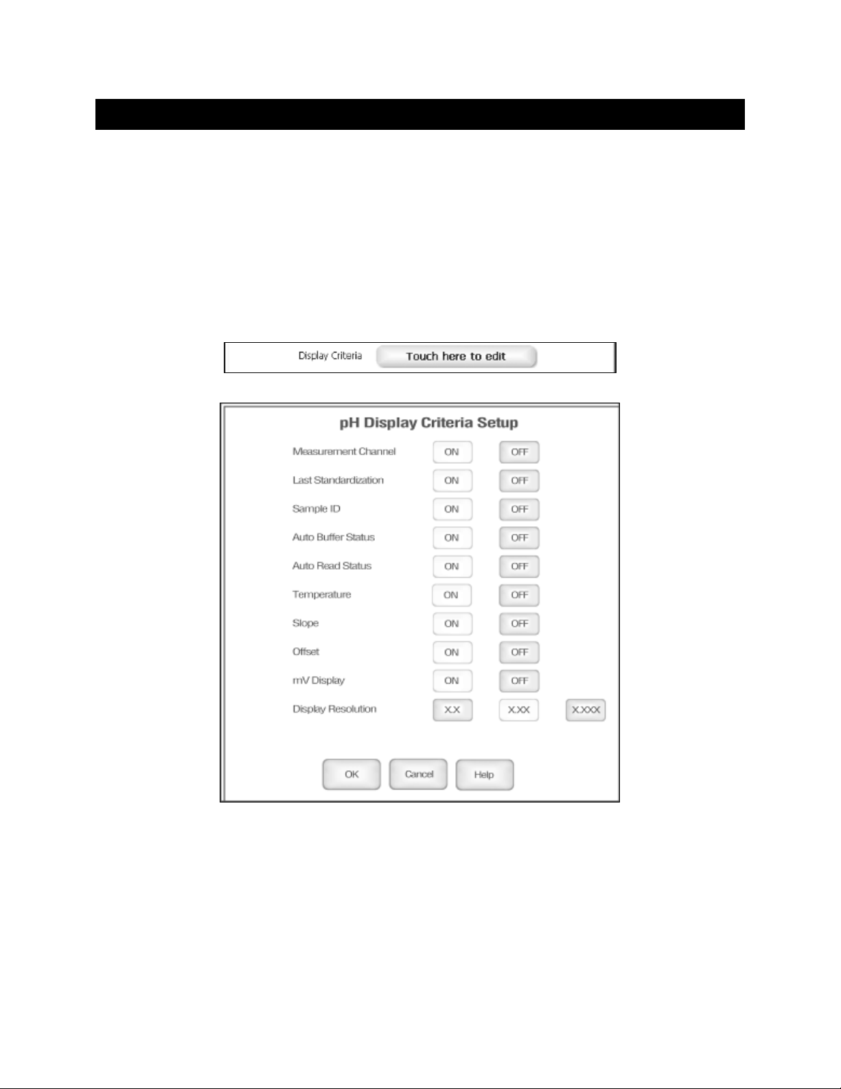
16. PARAMETER SETUP: DISPLAY CRITERIA
The Display Criter ia setting is avail able from any para meter Setup. Use t his opt ion to selec t which c riteria
to appear during measurement.
To Set Display Criteria:
1. Select Touch here to edit next to Data Storage Criteria.
2. Select ON or OFF for each detail.
3. Select OK to accept your selections.
22
Page 23
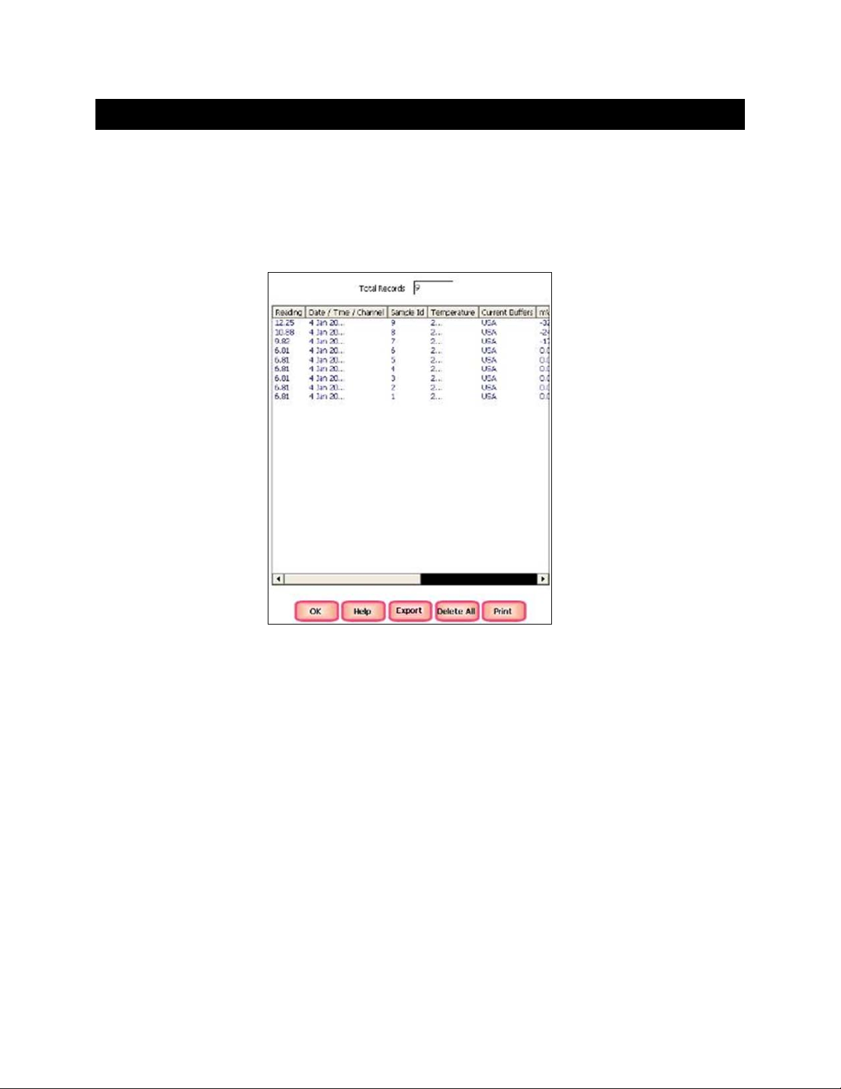
17. VIEWING & EXPORTING STORED DATA (LOG VIEW)
The Log View icon available from the measurement screen gives you access to exam ine specific data
points stored in the meter. View up to 2000 data points that have been saved to memory per user ID.
Drag the column width to extend the column for better visibility.
Connect a USB drive to the USB-A port an d s e lect “ Export” to quickly and easil y save your data. Records
will be collected until the maximum limit has been reached or until “Delete All” is selected.
23
Page 24
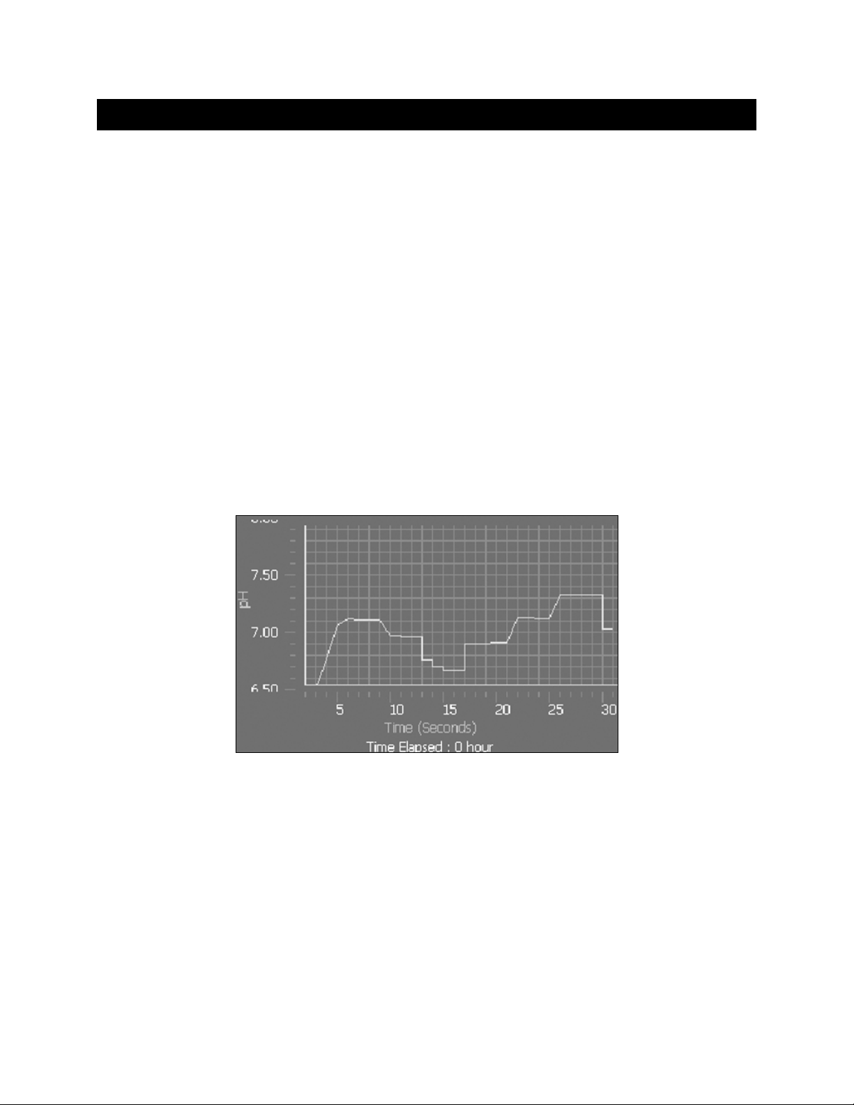
18. GRAPHING
From Single Channel m easurement, r eal-time data can be viewed on a graph t o view changes over br ief
or extended periods. Time is plotted in seconds. The graph refreshes every hour from the start
of graphing.
Follow The Steps Below:
1. Select Show Graph. A graph will be displayed on the lower half of the screen where various
measurement details were pr eviously displayed.
2. To track live measurement data on the graph, select Start Plotting. The measurement data will
continue until Stop Plotting is selected. When stopped, the graph can be dragged left/right and
up/down.
3. To examine the data more closely, select touch Zoom In. To view more data at once one time, touch
Zoom Out.
4. To remove the graph display and revert to display measurement data on the lower half of the screen,
select Hide Graph.
Note: Measurement data will continue to be tracked on the graph until Stop Plotting is selected.
Hide Graph only removes the display; it does not prevent data from collecting.
24
Page 25
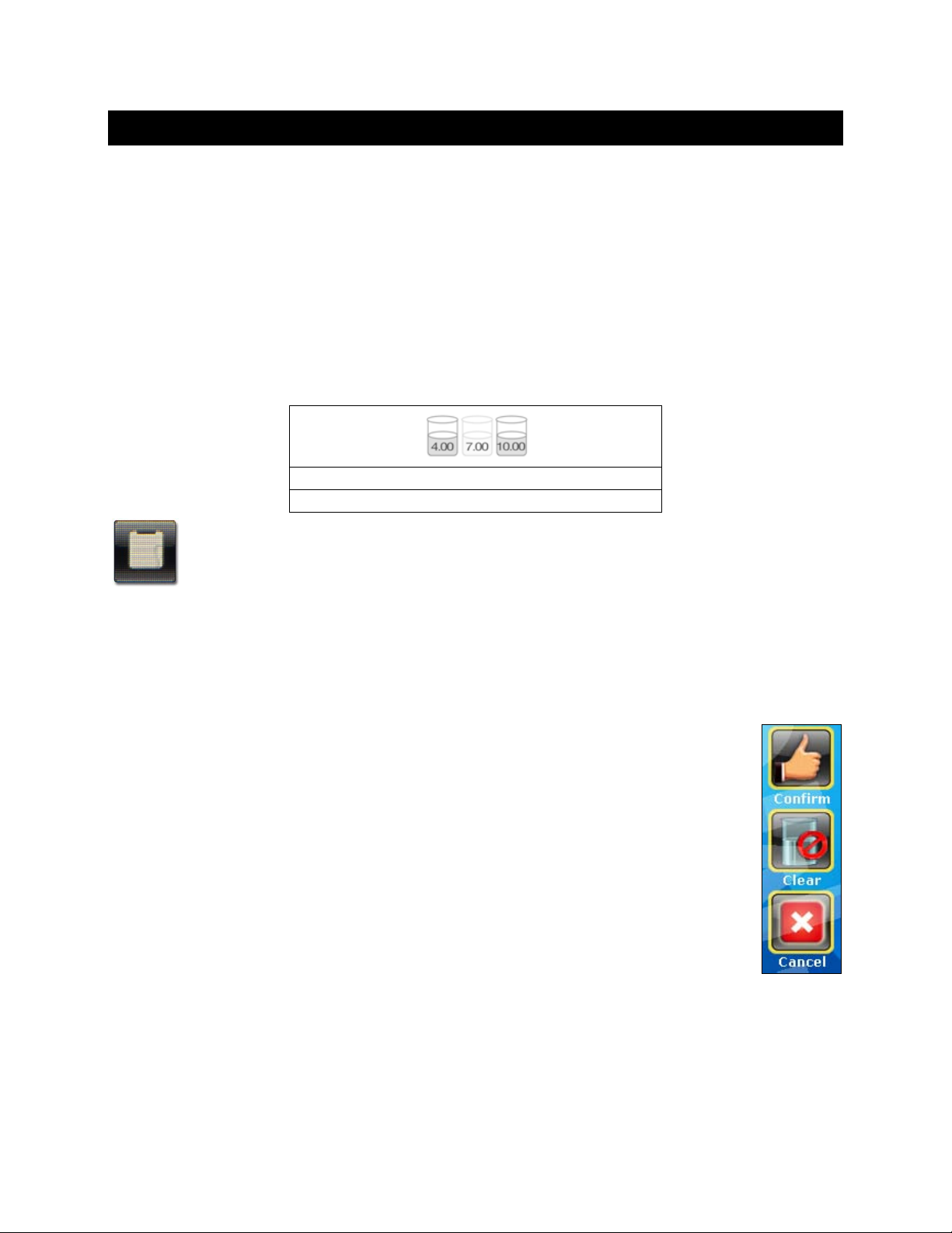
Last Standardization : 2012-08-30, 1:23:45 PM
Current Buffer Group : USA
19. STANDARDIZATION
This section is a general standardization guide for all parameters. Additional param eter specific details
can be found in the respective parameter sections of this reference guide.
The purpose of Standardization of any parameter is to maximize accuracy. After storing values of
known accurate standards into memory, samples with unknown values can be measured against
these standards.
If the standardization has been erased or there is no active standar dization; “Not standardized” will be
shown below the display.
When an active standard ization being applied to the m easurement, the details will be shown be low the
display such as the values stored in calibration, date/time, and buffer group/method;
Note: A detailed history of Standardizations that have been performed can be viewed from
the measurement screen by selecting the “Std. View” icon as shown at left.
Follow The St eps Below For A Typical Standardization:
1. From the Single Channel measurement display of the parameter you wish to standardize, immerse
your clean/ rinsed electrode(s) into a known standard solution and stir gently.
2. Select Standardize.
3. Select Clear to erase the previous standardization, or Cancel to return to measurement
at any time. Continue to step 4 to add or modify a value from the existing standardization.
4. A beaker or series of beakers will blink and rotate as the meter searches for the
appropriate standard value. Once the standard value is determined and the reading has
stabilized, “STABLE” will appear. A keypad will appear if the standard value requires
manual entry.
5. Select Confirm to accept the value and return to measurement screen. A warning
message will appear if the standardi zat ion is accepted by the instrument but is not within
range. An error message will appear if the standardization is not accepted.
6. Repeat steps 2-5 with addition al standards.
25
Page 26
Ion Operation:
XL25, 50 and 60 meters
Incremental Methods
20. TEMPERATURE OPERATION
The thermistor sensor used for automatic temperature compens ation and measurement is accurate and
stable, so frequent calibration isn’t required. Temperature calibration is recommended upon electrode
replacement, whenev er th e tem peratur e rea ding is suspec t, or if m atching ag ains t a certif ied th erm omet er
is desired.
The maximum adjustable value is ±5 °C or ±9 °F from the factory default temperature value.
If an automatic tem perature com pensation (AT C) probe is not conn ected, a W arning m essage will pop u p
indicating that Temperature probe has not been connected and return to measurement.
Follow The St eps Below To Standardize Temperature:
1. Connect the ATC probe and place it into a solution with a known accurate temperature
such as a constant temperature bath. The temperature probe may be independent or
part of a pH, or conductivity, or DO electrode. Note that pH electrodes with built-in ATC
will have separate connections for pH (BNC) and ATC (mini-phone). Conductivity and
DO electrodes do not have separate ATC connections. For multi-channel instruments,
ensure that your electrode is connected to the corresponding ATC channel which you
are viewing.
2. When the temperature reading is stable, select Standardize from any measure screen,
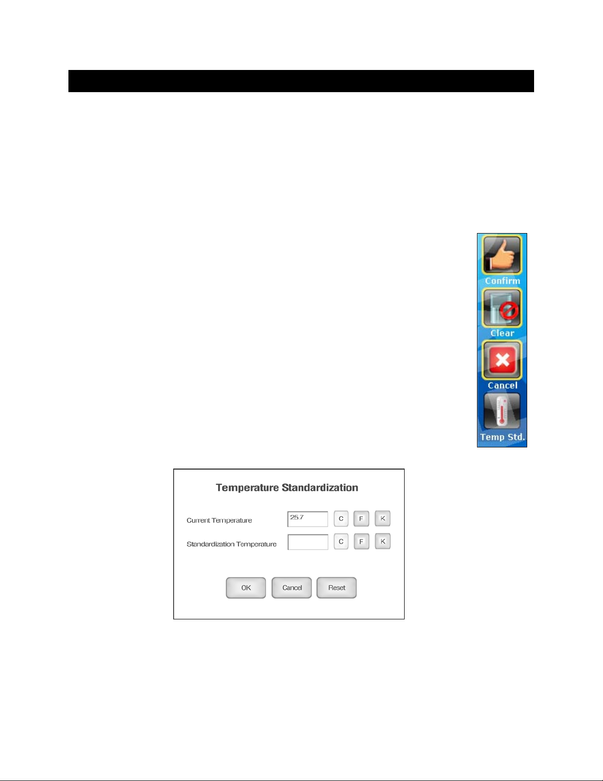
and then select the Temp Std. icon.
3. The upper display shows the current factory default temperature without standardization,
while the lower display will be the new standardization temperature.
4. To enter a new Standardization Temperature, select the box and enter value using the
keypad that will appear.
5. Select OK to accept the new temperature.
26
Page 27
Ion Operation:
XL25, 50 and 60 meters
Incremental Methods
21. PH OPER ATION
This section will re view operations which are spec ific to the pH p arameter. Pleas e refer to other s ections
for additional information on operations which are common to all measurement parameters.
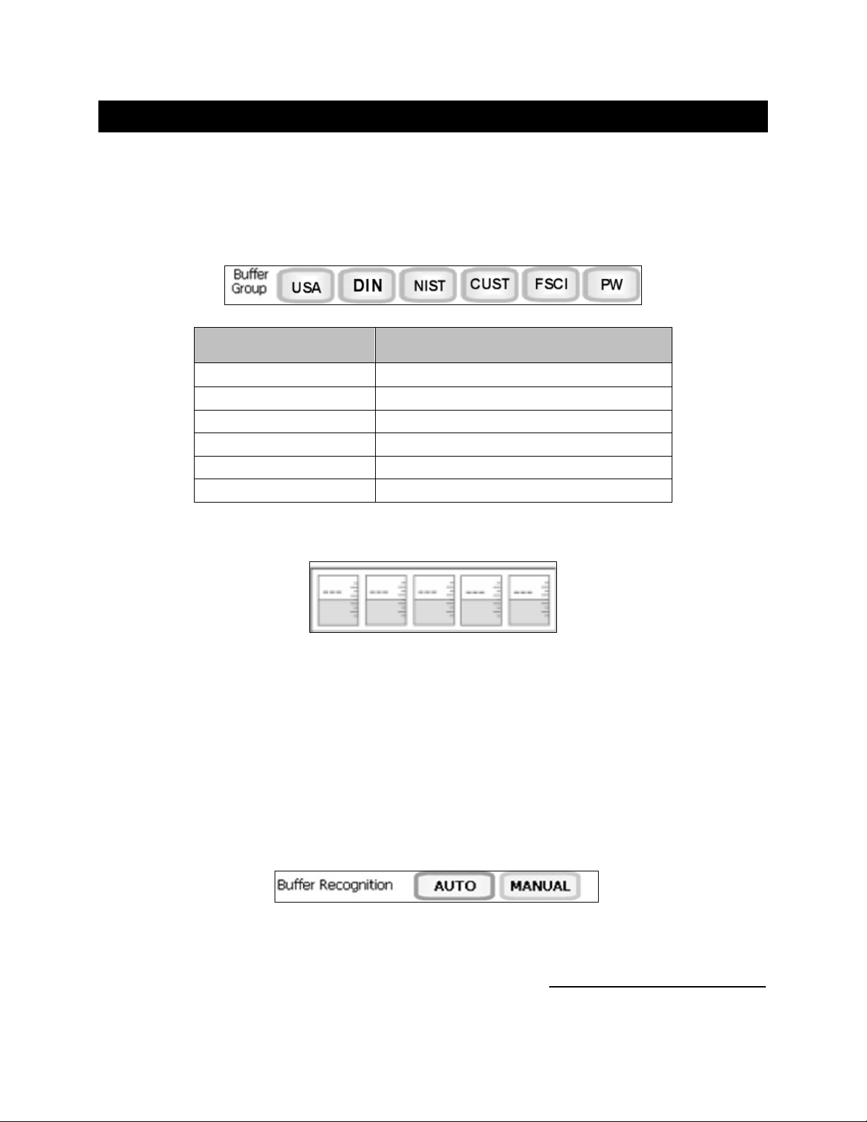
In pH Setup, select one of (6) different buffer groups shown below, based on the known pH standard
values you have selected to use for Standardization.
Buffer Group pH Values
USA
DIN (19267)
NIST
CUSTOM
FSCI (Fisher Scientific)
PW (Pure Water)
If CUSTOM Buffer Group Is S elected, (5) Beakers Will Appear:
2.000, 4.010, 6.997, 10.013, 12.000
1.090, 3.060, 4.650, 6.790, 9.230, 12.750
1.678, 4.010, 6.865, 9.184, 12.460
Any 2-5 values, ≥ 1.0 pH unit apart
1.000, 3.000, 6.000, 8.000, 10.000, 13.000
4.10, 6.97, 9.15
1. Select any empty beaker to display the numeric keypad.
2. Using the keypad, type the custom pH buffer value, and press Enter to accept the value.
3. Repeat steps 1 & 2 to enter up to 5 custom buffer values. At least 2 values must be used.
4. To modify an existing value, touch the beaker and key in the new value.
5. To erase all custom buffer values, select CLEAR.
In pH Setup, select either Autom atic or Manual Buffer Rec ognition. Automatic (def ault) is appropriate f or
most users.
Automatic buffer rec ognition will a utomatic ally recog nize the values i n your se lected b uffer group, savi ng
you time. This will also pro vide a hi gh le vel of accurac y as th e instr um ent can sta ndard ize to values in the
instruments memory at various temperatures.
Manual buffer recognition requires manual entry of the buffer value
during standardizatio n. Since manual buffer recognition is not p ossible with pre-assigned buffer groups,
the CUSTOM buffer group is assigned by default when “MANUAL” buffer Recognition is selected.
at the specific buffer temperature
27
Page 28

Ion Operation:
XL25, 50 and 60 meters
pH Standardization Notes:
For best results, periodic standardization (calibration) with known accurate standards is recommended
prior to measurement. Use standards that bracket your intended measuring range while including a
neutral point (7.00, 6.8 6, or 6.79). For example, if you expect to m easure samples from pH 6.2 to 9.5,
calibration with 4.01, 7.00, and 10.01 will work well. Do not reuse buffer solutions after calibration.
Verify the pH and ATC ele ctrodes connected to the m eter in Channel 1 or Channel 2 correspon d to the
respective measurement channel on the display.
To eliminate temperature errors associated with the pH electrode, attach the automatic temperature
compensation (ATC) probe for best accuracy. Without temperature compensation, pH accuracy will
decrease as samples deviate from 25 ºC and pH 7 or 0 mV.
If the pH electrode has be en stored dry, soak in storage solution f or 10 minutes before standardization
to saturate the pH electrode s urface and minimize drift. If s torage solution is not available, use a neut ral
pH buffer. While OK for rinsing, do not store pH electrodes in deionized or distilled water as this will
dehydrate the electrode and decrease performance.
The efficiency of the electrode is reported as the slope. Slope can be described as percentage where
100 % is ideal, or as a mV/decade unit. When performing standardization with 3 or more standards,
multiple slopes will be calculated by the instrument. The slope that appears on the screen during
measurement, is the slope which is applicable to the zone in which the measurem ent is currently being
made. For example, if pH 4, 7, and 10 are standardized, and a sample of pH 5 is being measured,
the slope displayed would be the slope calculated between 4 and 7. The slopes are independent of
each other.
If Auto Read func tion is "ON", the meter w ill freeze the measurem ent as soon as the STABLE indicator
appears. Once locked, the reading will not change until Measure is selected.
Do not reuse buffer solutions after calibration – especiall y pH 10 which drifts with prolonged exposure
to air.
Check to ensure that t he r e f erenc e j unc tion of the electrode is not clogged, t he ref er enc e f ill s ol uti on is not
contaminated or disc olored, and t he electrode has a p roper level of the correct f illing soluti on appropria te
for the electrode used. Any of these conditions can lead to erratic or drifting measurements.
Avoid prolonged exp osure of the pH g lass to alk aline, organic, surf actant and h ydrofluoric acid so lutions.
Each of these will deteriorate the pH response of the glass. After measurement, remove the electrode
from the sample rinse with clean water, and plac e the electr od e into your storage solution.
If immersed in soluti on, the fill-ho le of the refil lable elect rode should be unc overed in the open positio n to
prevent proper electrolyte flow.
When possible, pro vide stirring to the standar ds and sam ples. This s peeds up the r esponse, and permits
a more representative measurement.
Do not wipe the electrode. T his may impart a static charge, and result in an unstable read ing. A hydrated
electrode is important – rinse and shake dry without wiping.
Incremental Methods
28
Page 29
Ion Operation:
XL25, 50 and 60 meters
Incremental Methods
22. MILLIVOLT OPERATION
This mode is used to m easure oxidation/ reductio n potential (ORP/ Redox), perform titration, and to verif y
the function of the meter. The mV measure function al l o ws you to contin uo us l y monitor the mV potential of
the electrodes in use. This can be done in either absolute (abs) or relative mV (Rel mV).
In millivolt mode, the cur rent m illivolt output f rom the electrod es be ing used is monit ored and d ispl ayed on
the screen. The m eter will continually m onitor the millivolts readin g in this mode and wi ll not lock onto a
single reading. However, once the reading has become stable, the STABLE indicator will appear.
Relative mV Standardization:
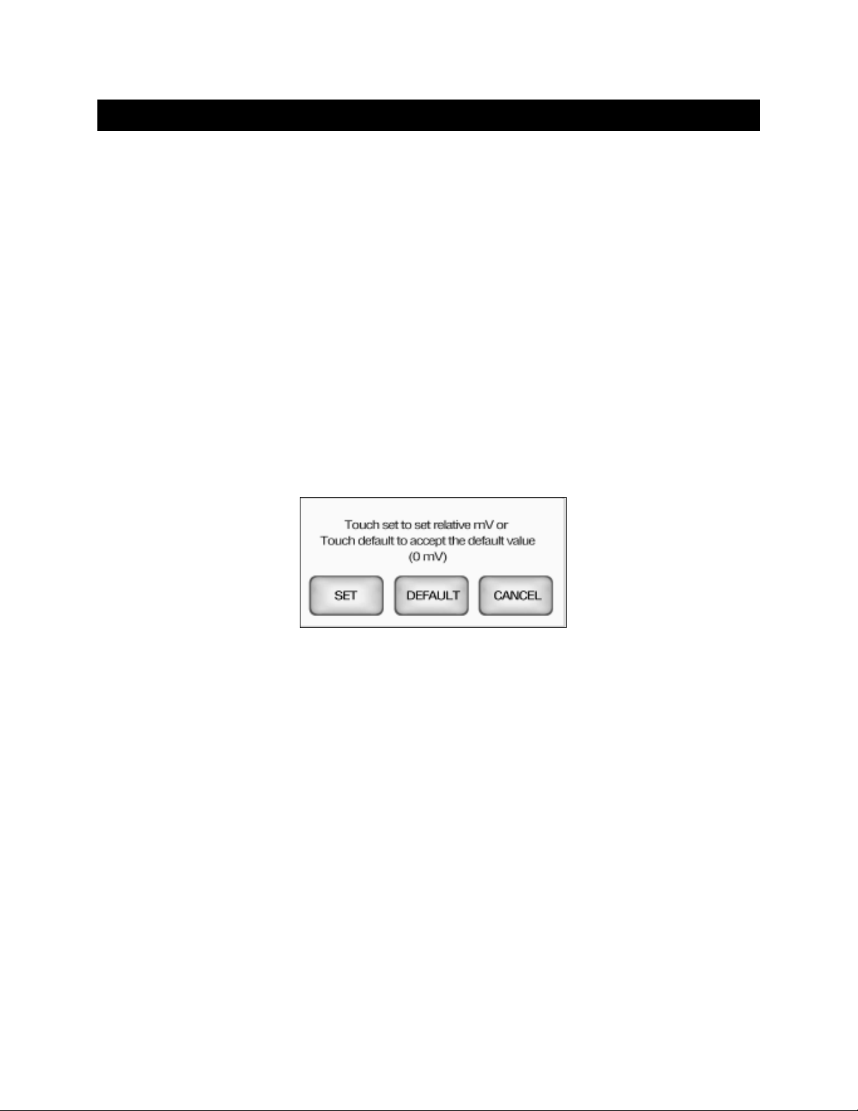
The relative mV mode allows adjustment of the displayed value ±150 mV.
1. After rinsing your electrode(s) with clean water, immerse into the mV (ORP) standard solution, provide
gentle mixing and wait for the STABLE indicator to appear.
2. Select Rel mV to access the Relative mV screen.
3. Select SET to set the relative mV using numeric keypad.
4. Select Enter to confirm the value, or DEFAULT to accept the default value (0 mV).
29
Page 30
Ion Operation:
XL25, 50 and 60 meters
Incremental Methods
23. ION: SETUP & OPERATION
Refer to your Ion Selecti ve Electr ode i nstruc tion m anual for details on c ond itionin g, stor age, m aintena nce,
calibration standard preparation, Ionic Strength Adjust ment, troubleshoot ing, etc. Each ISE is unique and
requires care and operation that is specific to the electrode and ion of interest.
Ion Method:
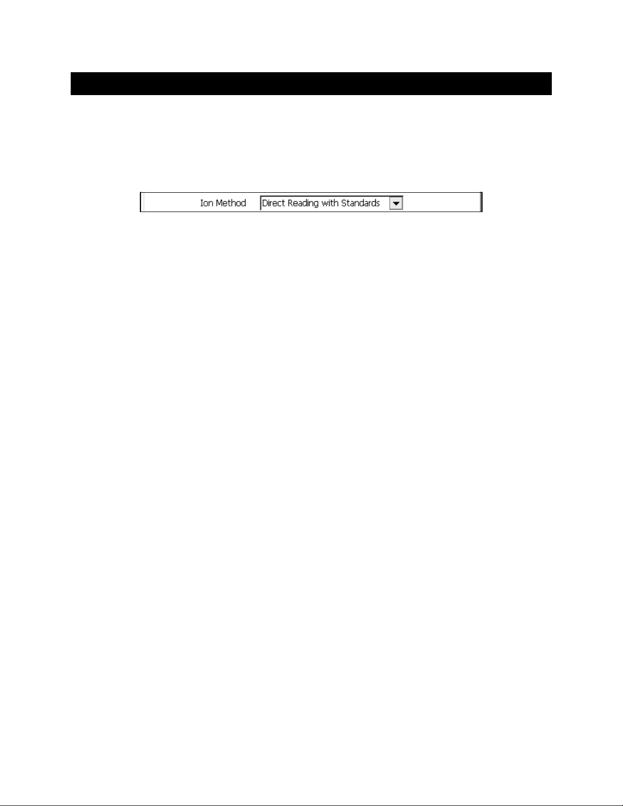
From Ion Setup, choose the desired Ion Method from the drop down menu:
Direct Reading with Standards: The most common method of ion measurement. When using this
method, you will use standards of known values to standardize the meter with ion standards. An ionic
strength adjuster (I SA) is added to both the sta ndards and the sample. T wo to five standards are used.
The standards should brac k et the expected va lue of the s am ple. The ion spec ific elec trode is imm ersed in
a stirring sample and the ion concentration is read directly from the meter.
Direct Reading with Blank Offset: Commonly used for det erm ining ion concent ration i n a sam ple with a
very low level of ions. D ue to bac kgr ound interf erenc e at lo w concentr atio n levels , a bla nk is used and the
value of the ion concentration in the blank is subtracted from the value of the measured sample.
Known Addition Method: An incr emental method used for sam ples with a complex matrix. A standard
with a known concentrat ion of the ion species of interest is added to t he sample. The difference in m V
potential is then used to calculate ion concentration.
Known Subtraction Method: An incremental method where the ion of interest in the sample is not
identical to the io n in the st andard solut ion. The stan dard of known ion concentr ation that is added to t he
sample quantitatively reacts in the sample with th e ion of interes t. This reaction removes a fix ed amount of
the ion of interest from the sample solutions. The ion concentration is then calculated based upon the
difference in the mV potential.
Analate Addition: A m odification of the k nown addition m ethod. The initial m V measurement is r ecorded
in a standard solution. T he ion in the standard solutio n is the ion of interest and is detected b y the ion
selective electrode i n use. A sam ple containing the ion of interest is then added to th e standard solut ion.
The difference in the mV potential is the n used in the calc ula tion of the concentra tion of the i on of interest.
This method is useful if the sample temperat ure is significantly dif ferent than that of the standar d. When
the small volume of hot sample is added to the larger volume, the temperature impact becomes negligible.
Analate Subtraction: Useful when there is no ion specific electrode available to directly measure the
concentration of the ion of i nterest. This m ethod employs the ad dition of a sam ple of the ion of interes t to
a standard containing a dif ferent ion of known concentration. The ion of interest will quantitatively react
with the ion in the standard , creating a complex and r emoving the ion f rom the standard sol ution. The ion
specific electrode is specific for the ion in the standard solution and not for the ion of interest. The
difference in mV potential is used to calculate the concentration of the ion of interest based upon this
quantitative reaction.
30
Page 31
Ion Operation:
XL25, 50 and 60 meters
Tip: If you will use multiple ISE electrodes, it is a good idea to create a
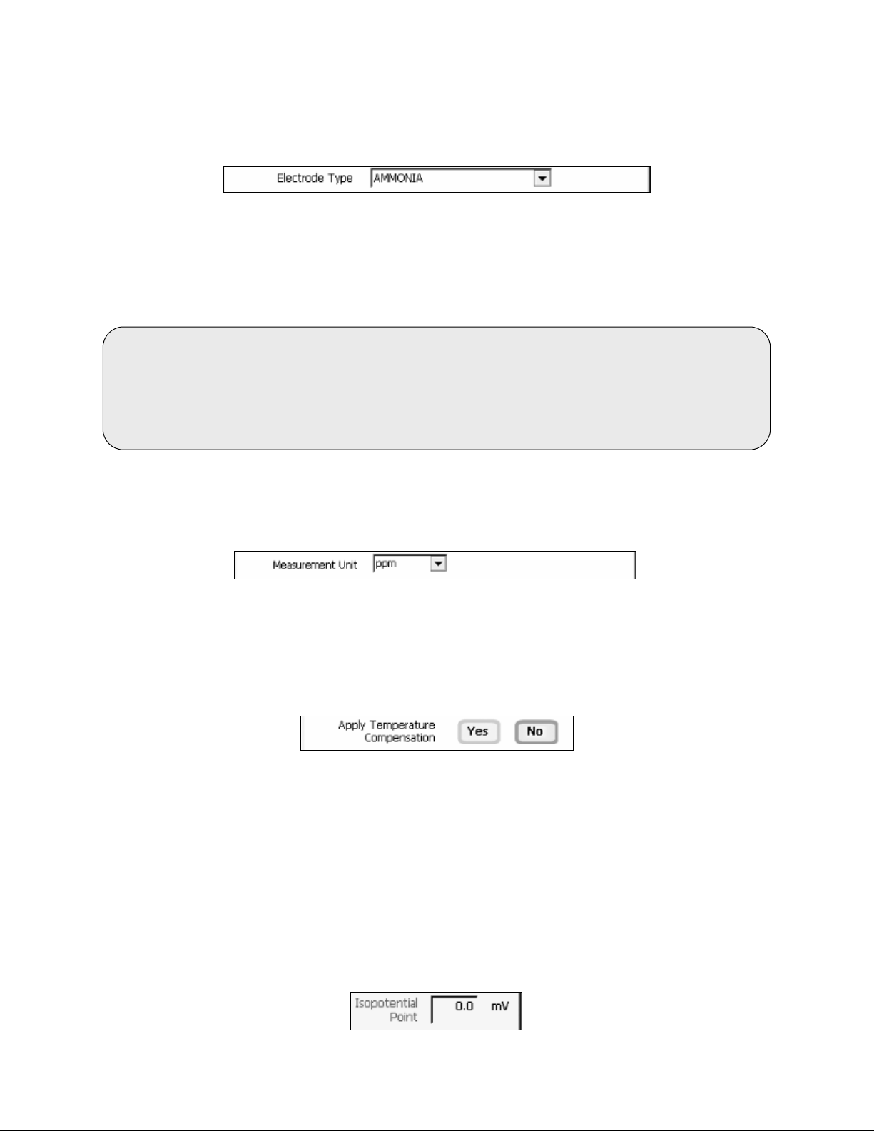
Electrode Type:
From Ion Setup, choose the desired Electrode Type from the drop down menu:
The choice of electrode informs the meter which default slope to use in the calculations made for
electrode efficiency and sample concentration. The default slope value is a theoretical value of the
electrode selected. A two point minim um standardization is re quired to det ermine the actual ef ficiency of
your electrode.
Changing the electrode type will erase the previous standardization.
Incremental Methods
Select Measur ement Units:
This screen lets you select the un its in which the m eter will r eport the concent ration of the ion of inter est.
The current units are displayed on the screen.
Apply Temperature Comp ensation:
Ion concentration is a temperature dependent measurement. Best results are obtained when the
standards and the sam ples are standardized and measured at the same temperature. Ho wever, if you
have experimentally determined the isopotential point of your electrode then you can choose to set ATC to
YES and enter the isopotential value. Otherwise, this option should be left as “NO” by default which is
most common.
different User ID for each electrode used, Such as User ID = “Ammonia”,
“Fluoride”, or “Na K” if you are testing two channels for Sodium and Potassium
simultaneously. This will retain the individual parameter settings,
calibration information, and stored data together.
Set Isopotential Point:
The isopotential point is the millivolt reading for an electr ode at which temperature has no effec t on the
measurement. Ion Select ive Electrodes, unlik e pH electrodes, are not desig ned to achieve any partic ular
isopotential point. If samples and standards are at different temperatures when performing ISE
experiments, it will be necessary to experimentally determine the isopotential point of your own Ion
Specific Electrode.
1. From Ion Setup, Select the Isopotential Point value and use the numeric keypad to enter the desired
mV setting for the new isopotential point.
2. Touch Enter to accept this value and return to Ion Setup screen.
31
Page 32

Ion Operation:
XL25, 50 and 60 meters
Tip: The STABLE indicator will only appear upon completion of a successful two
standards, a series of dashes will appear in place of a measurement value.
Incremental Methods
24. ION: DI RECT READING METHODS
There are two direc t re ad in g methods – Direct Reading with Standards and Direct Reading with Blank
Offset. These t ypes of measurements allow you to direc tly read the concentration of your s ample after
standardizing the meter with ion standards of known values or blank values.
Direct Readin g W ith Standards :
This is the most common method of ion measurement. You can directly read the concentration of
the sample after standardizing the meter with known ion standard solutions. An ionic strength adjuster
(ISA) is added to both the s tand ards and the sam ple. T he stan dards should brack et the ex pecte d value of
the sample.
You must use a minimum of two standar ds to standardize the meter. For best results alw ays begin with
your lowest calibration standard value, followed by the next lowest, and so on.
1. Rinse and immerse your clean Ion selective electrode which has been prepared according to the
electrode instruction manual into a known standard solution and stir gently.
2. Select the Standardize icon. "Clear" will delete the previous standardization values and "Cancel" will
return to measurement mode.
3. A keypad will open after one scanning cycle. Using the displayed keypad, input the value of the known
standard solution you are using and press "ENTER".
4. The meter will show the value which can be seen blinking on the display.
5. Wait for the reading to stabilize (Tip: observe the millivolt value). When stable, select “Confirm” to
accept the standardization.
6. Repeat steps 1-5 with additional ion stand ar ds.
point standardization. If the meter has not been st and ar di zed with at least two
Direct Readin g W ith Blank Of fs et:
This method is useful for measuring samples with low level concentrations of selected ion of interest.
It eliminates background in terference by subtracting t he value of a blank concentration from the value of
the sample. You must use a minimum of one blank and two stand ards for this method. F or best results
always begin with your blank, followed by your lowest calibration standard value, followed by the next
lowest, and so on.
1. Add ionic strength adjuster as needed to the calibration standards and the blank.
2. Rinse and immerse your clean Ion selective electrode which has been prepared according to the
electrode instruction manual into your solution blank or lowest calibration standard value and stir gently.
3. Select the Standardize icon. "Clear" will delete the previous standardization values and "Cancel" will
return to measurement mode.
32
Page 33

Ion Operation:
XL25, 50 and 60 meters
4. When prompted with "Is this reading STANDARD or BLANK?”, select
the appropriate choice.
- If BLANK is selected; a BL ANK beaker icon will be visible from
the measurement screen with the mV value. Continue with step 2
using ion standards instead of blank.
- If STANDARD is selected; a keypad will open after one scanning
cycle. Using the displayed k e ypad, input the value of the known
standard solution you are using and press "ENTER".
5. The meter will show the value which can be seen blinking on
the display.
6. Wait for the reading to stabilize (Tip: observe the millivolt value). When stable, select “Confirm” to
accept the standardization.
7. Repeat steps 2-5 with additional standards.
Incremental Methods
33
Page 34

Ion Operation:
XL25, 50 and 60 meters
Incremental Methods
25. ION: I NCREMENTAL METHODS
The incremental m ethods which inc lude known ad dition, known subtraction, ana late addition and analate
subtraction are part icularly useful with samples conta ining complex ionic backgrounds which cannot be
matched in standards. They are also usef ul with oc c asion al samples whose temperatures var y.
Standardizing The Meter For All Increment al Methods:
Prior to conducting an analysis using an y of the incremental m ethods, it is necessar y to standardize the
meter with at least two standards. This will establish a slope value for the elect rode in use. The slope
value is required in the incremental method calculations which yield the ion concentration of the sample.
Make sure you have selected one of the incremental methods (known addition, known subtraction,
analate addition, or analate subtraction) in the Ion Setup screen.
34
Page 35
26. ION: KNO WN ADDITION METHOD
When performing know n addition, you will ad d an aliquot of standard so lution c ontaining the io nic speci es
of interest to a k nown volume of your sample. The mV readings of the sample can the n be calculated
based upon the dif ference in the m V readings. The u se of the increm ental methods requires that certain
parameters be ident ified. In addit ion to the m illivo lt of t he elec trode( s) in both the sample and sample plus
standard, it is necessar y to enter the volume of the sam ple, the volume of standard, the volum e of Ionic
Strength Adjuster (IS A) if used, the concentration of the standard, and the slo pe of the electrode in use.
The meter will prom pt you through the m ethod, permitting you to enter the appropriate parameters at the
appropriate time. When the meter has all of the data needed for the calculation, it will display the ion
concentration of the sample as well as the parameters entered for the calculation.
The standard concentrat ion should be hig h enough to nearl y double the sam ple ion c oncentratio n after its
addition. However, the sta ndard volume should not signif icantly impact the sam ple volume. A 1:100 ratio
of standard to sample is optimal. For a monovalent electrode, the standard addition should result in a
15-30 mV change. For a divalent e lectrode, a 7-10 mV change is adeq uate. If the millivolt change is too
high, the addition of the standard may affect the ionic strength and therefore the activity coefficients.
This could result in inaccurate measurements. If the millivolt change is too small, readability errors
are enhanced.
You must use a minimum of two standards to standardize the meter.
1. Immerse the ion selective electrode in a known volume of the sample solution and stir gently.
2. Wait for the reading to stabilize. Touch "KA" to accept the current reading as first mV reading.
3. Add a known volume of standard solution to the sample.
4. Wait for the reading to stabilize. Touch "KA" to accept the current reading as second mV reading.
5. Use the keypad to enter the sample volume.
6. Select “Enter” to accept the value.
7. Use the keypad to enter the standard volume.
8. Select “Enter” to accept the value.
9. Use the keypad to enter the volume of the ISA solution added.
10. Select “Enter” to accept the value.
11. Use the keypad to enter the concentration of the standard solution
added to the sample.
12. Select “Enter” to accept the value.
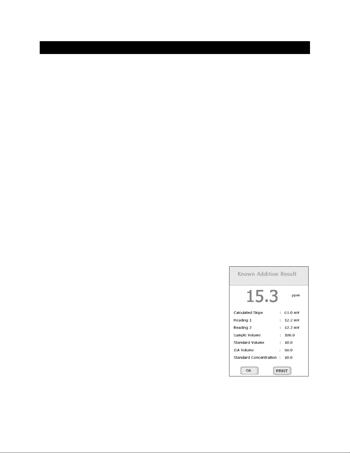
13. The Known Addition result is now displayed. Select “Print” to send
the data to Printer if sample ID# has been assigned, or Select “OK” to
return to the Measure screen for a new measurement.
35
Page 36
27. ION: KNOWN SUBTRACTION METHOD
The procedure for known subtraction is very similar to that for known addition method. An aliquot of
standard is added to a k nown volume of the sample. The dif ference is that th e standard does not c ontain
the same ionic speci es that you are trying to m easure in the sample. Inste ad, it contains an ion t hat will
complex or precipitate the ion of interest, removing it from the sample. Like known addition, the mV
readings are tak en before and af ter the sta ndard is added to the sam ple and th e differenc e in mV values
can be used to calculate the c onc entration of free ions of interes t in the sample. This method also requires
you to enter values of certain parameters in order to obtain an ion concentration.
You must use a minimum of two standards to standardize the meter.
1. Immerse the ion selective electrode in a known volume of the sample solution and stir gently.
2. Wait for the reading to stabilize. Touch "KS" to accept the current reading as first mV reading.
3. Add a known volume of standard solution to the sample.
4. Wait for the reading to stabilize. Touch "KS" to accept the current reading as second mV reading.
5. Use the keypad to enter the sample volume.
6. Select “Enter” to accept the value.
7. Use the keypad to enter the standard volume.
8. Select “Enter” to accept the value.
9. Use the keypad to enter the volume of the ISA solution added.
10. Select “Enter” to accept the value.
11. Use the keypad to enter the concentration of the standard solution
added to the sample.
12. Select “Enter” to accept the value.
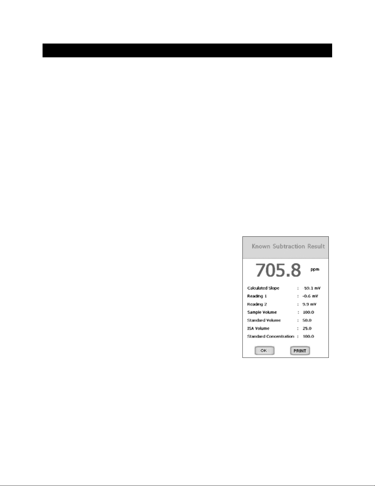
13. The Known Subtraction result is now displayed. Select “Print” to
send the data to Printer if sample ID# has been assigned, or Select
“OK” to return to the Measure screen for a new measurement.
When using the Known Addition/Subtraction or Analyte Addition/
Subtraction, the current mV value will be shown as measured value
instead of "----".
36
Page 37
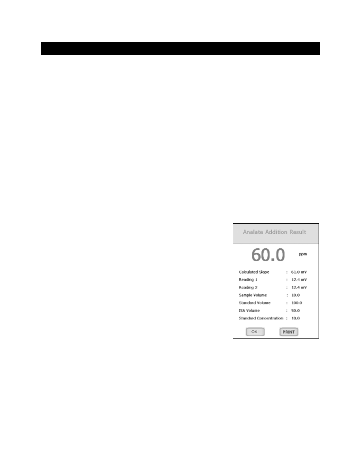
28. ION: ANALATE ADDITION METHOD
The analyte addit ion method is useful when your sample is at an elevated temperature and you want to
negate the effec t that temper ature will have on the co ncentrat ion calcu lation. T his method is also us eful if
you have only a small amount of sample available. The anal yte addition method diff ers only slightly from
the known additio n method. The differ enc e b ei ng the s olut ion that you are taking your in itial mV re ad in g i n
is actually the standard and not the sample of interest. The difference in mV reading of the standard
before and after the s ample is a dded is used to ca lculate t he concentr ation of the io n of interes t. W ith the
analyte addition method, both the sample and the standard solution contain the ionic species of interest.
You must use a minimum of two standards to standardize the meter.
1. Immerse the ion selective electrode in a known volume of the sample solution and stir gently.
2. Wait for the reading to stabilize. Touch "AA" to accept the current reading as first mV reading.
3. Add a known volume of standard solution to the sample.
4. Wait for the reading to stabilize. Touch "AA" to accept the current reading as second mV reading.
5. Use the keypad to enter the sample volume.
6. Select “Enter” to accept the value.
7. Use the keypad to enter the standard volume.
8. Select “Enter” to accept the value.
9. Use the keypad to enter the volume of the ISA solution added.
10. Select “Enter” to accept the value.
11. Use the keypad to enter the concentration of the standard solution.
12. Select “Enter” to accept the value.
13. The Analyte Addition result is now displayed. Select “Print” to send
the data to Printer if sample ID# has been assigned, or Select “OK”
to return to the Measure screen for a new measurement.
When using the Known Addition/Subtraction or Analyte Addition/
Subtraction, the current mV value will be shown as measured value
instead of "----".
37
Page 38
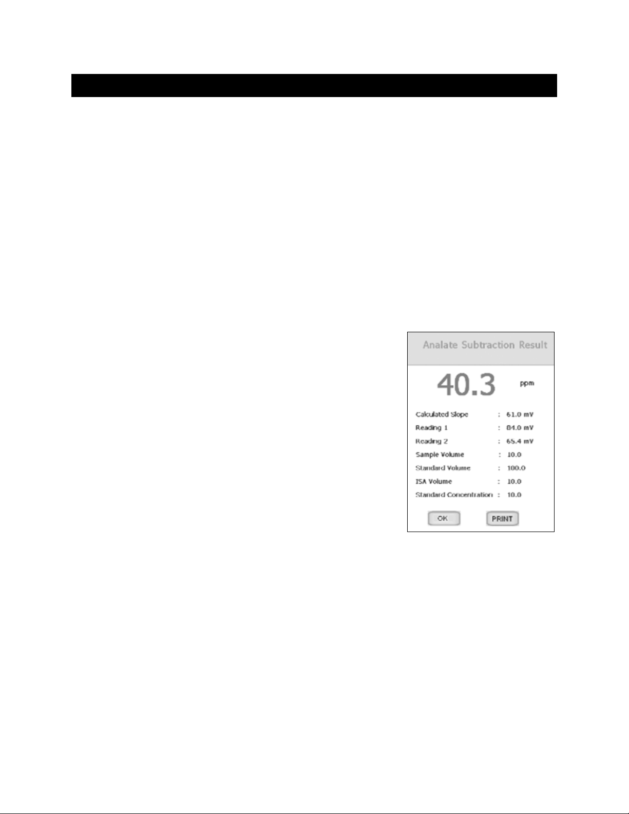
29. ION: ANALATE SUBTRACTION METHOD
The analyte subtraction m ethod is usef ul when no ion spec ific electrode is availab le to meas ure the ion of
interest directly. Sim ilar to the Known Subtrac tion method, the sam ple and the standard c ontain different
ionic species. However, the ion bei ng measured is in the s ta ndar d a nd not in th e s am ple. The reduction of
free ions in the standard solution is proportional to the concentration of the ion of interest in the sample.
1. Immerse the ion selective electrode in a known volume of the standard solution and stir gently.
2. Wait for the reading to stabilize. Touch "AS" to accept the first mV reading of sample.
3. Add a known volume of sample solution to the standard.
4. Wait for the reading to stabilize. Touch "AS" to accept the second mV reading of sample.
5. Use the keypad to enter the sample volume.
6. Select “Enter” to accept the value.
7. Use the keypad to enter the standard volume.
8. Select “Enter” to accept the value.
9. Use the keypad to enter the volume of the ISA solution added.
10. Select “Enter” to accept the value.
11. Use the keypad to enter the concentration of the standard solution.
12. Select “Enter” to accept the value.
13. The Analyte Subtraction result is now displayed. Select “Print” to
send the data to Printer if sample ID# has been assigned, or Select
“OK” to return to the Measure screen for a new measurement.
When using the Known Addition/Subtraction or Analyte Addition/
Subtraction, the current mV value will be shown as measured value
instead of "----".
38
Page 39
30. CONDUCTIVITY / RESISTIVITY OPERATION
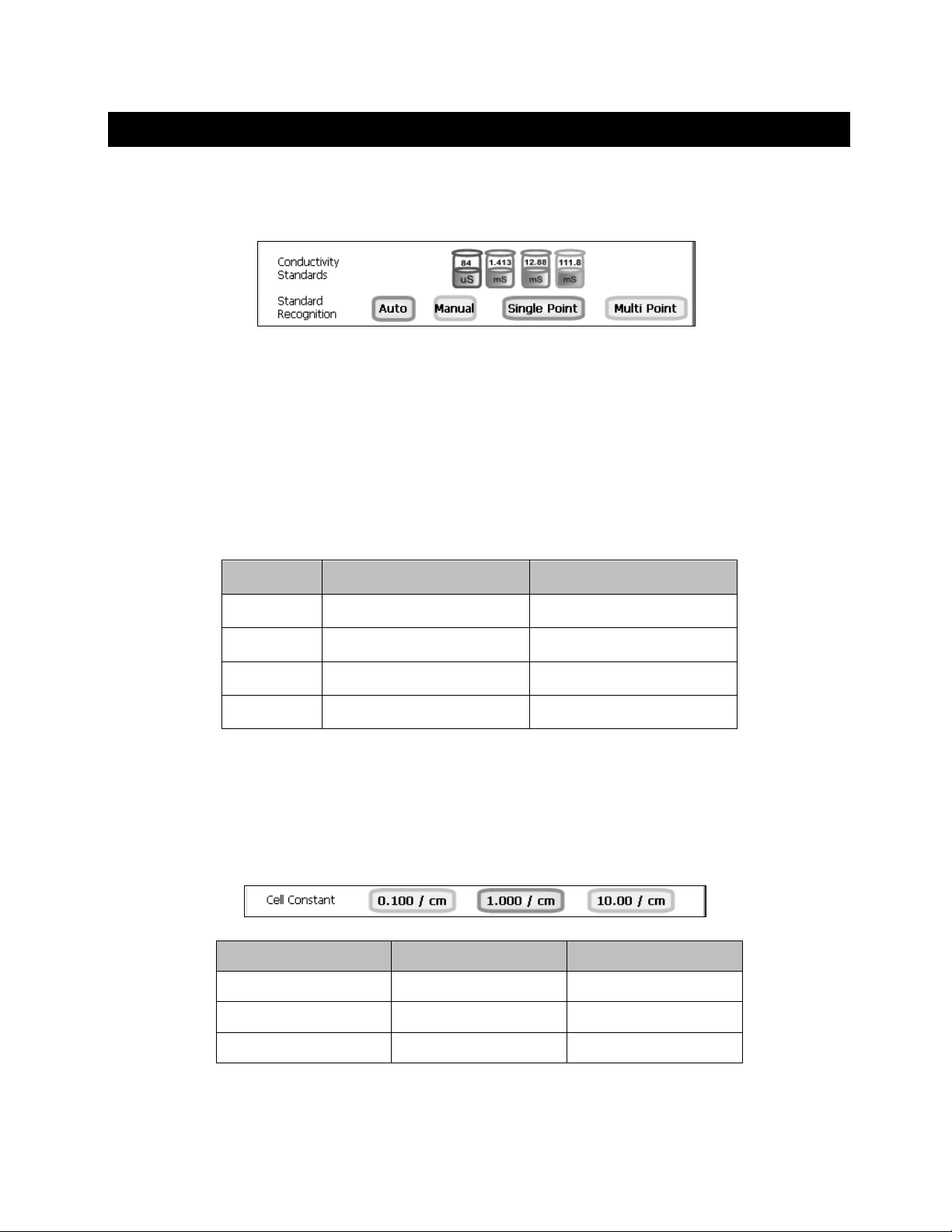
Standard Recognition:
This setup option shows the conductivity standards available for auto standard recognition. If Manual
standard recognition is selected, the area will be blank.
From Conductivity Setup icon, select AUTO to automatically recognize (84µS, 1.413mS, 12.88mS, or
111.8mS) values dur ing standardization. If you wil l only use one or more of the (4) calibration standards
listed here, automatic c alibration is rec ommended. O therwise, manual ca libration s hould be selected. T he
factory default is automatic conductivity calibration. Select MANUAL to manually enter the conductivity
value of your standard during standardization.
Single Point: Standardization will apply a single standard to all ranges.
Multi Point: Sta ndardization will ap ply a single standa rd to an individua l range. W hen using a Multi Point
Standardization, perform standardization in each range that you expect to use for best results.
Conductivity (/cm) Resistivity (/cm)
Range 1:
Range 2:
Range 3:
Range 4:
0.000 µS – 199.9 µS 0.000 Ω – 19.99 kΩ
200.0 µS – 1.999 mS 20.00 kΩ – 199.9 kΩ
2.000 mS – 19.99 mS 200.0 kΩ – 1.999 MΩ
20.00 mS – 500.0 mS 2.000 MΩ & above
Cell Constant:
Select the nominal cell con stant of the conduct ivity electrode you are using. Ther e are three cell consta nts
to choose from . Each is used for a d ifferent range. The follo wing indicates the o ptimal conductivity rang e
for the accumet conductivity cells. For resistivity measurements, an electrode having a nominal 0.1 cell
constant (13-620-101 or equivalent) is recommended.
Cell Constant 2-Cell 4-Cell
0.1 0.5 to 200 µS/cm Not Available
1.0 0.01 to 2 mS/cm 0.01 to 20 mS/cm
10.0 1 to 200 mS/cm 1 to 200 mS/cm
39
Page 40
Tip: For methods that requir e un-adjusted conductivity measurements,
Default Temp er ature:
The accumet conductivity electrodes include a built-in temperature sensor. Should the electrode be
removed or in the unlikel y event that the temperature portion should fail, the d efault temperature will be
used in its place. The factory default setting is 25 °C / 77 °F.
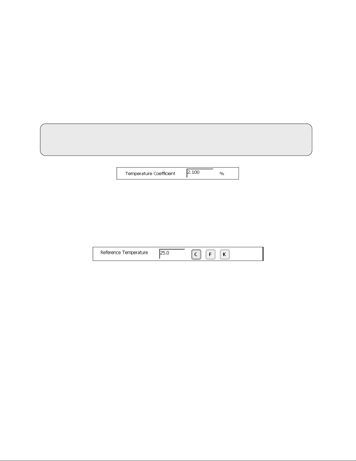
Temperature Coefficient:
The temperature coef ficient is the amount of change in conductivity per degree tem perature (% per ºC).
The factory default setting is a temperature coefficient of 2.1 % per ºC. For most applications this will
provide good results. The meter allows adjustment from 0.000 to 10.000.
set the temperature coefficient to 0.0%. This will allow
Reference (Normalization) Temperature:
temperature measurement without affect on the conductivity measurement.
When Automatic Temperature Compensation is used, measurements are adjusted by the temperature
coefficient % per degre e change, u ntil it reaches the refer ence (normali zation) tem perature. The ref erence
temperature is adjustable from 15.0 to 35.0 ºC.
Manually enter the reference temperature that is referenced on your calibration standard(s) typically
20 or 25 ºC.
40
Page 41
at 25 o C
TDS KCl
TDS NaCl
TDS 442*
ppm
Factor
ppm
Factor
ppm
Factor
84 µS
40.38
0.481
38.04
0.453
50.5
0.601
1413 µS
744.7
0.527
702.1
0.497
1000
0.708
12,880 µS
7447
0.578
7230
0.561
11,367
0.883
(200.0 - 999.9) x TDS factor ppm
31. TDS OPERATION
Electrochemical measurement of total dissolved solids (TDS) is determined by multiplying the electrical
conductivity (EC) by a (TDS) conversion factor. The factor is specific to the dissolved solids present and
can change with concentration. Measuring unknown solutions or a variable mixture of salts is difficult. Since
the factor will vary, TDS is not often as precise and repeatable as EC. While TDS is useful for certain
applications, EC is often preferr ed over TDS for these reasons.
Often conductivity calibration standards will include equivalent TDS values for common salts found in
solution such as can be seen in the table below:
Conductivity
*442 is an abbreviation for 40% sodium sulfate, 40% sodium bicarbonate and 20% sodium chloride,
it closely represents the conductivity to ppm relationship, on average, for naturally occurring fresh water
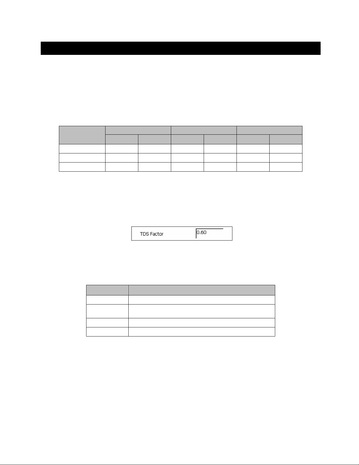
The TDS factor can be adjusted from the TDS Setup menu. Select the TDS factor appropriate for your
sample matrix fr om 0.40 to 1.00. N ote: when the T DS fac tor = 1.00, t he cond uctivit y value equ als the T DS
value. The factory default is 0.60.
Single Point: Standardization will apply a single standard to all ranges.
Multi Point: Sta ndardization will ap ply a single standa rd to an individual ra nge. When using a Multi Point
Standardization, perform standardization in each range that you expect to use for best results.
TDS
Range 1:
(0.000 - 199.9) x TDS factor ppm
Range 2:
Range 3:
Range 4:
(1.000 - 1.999) x TDS factor ppt
(2.000 - 19.99) x TDS factor ppt
(20.00 - 500.0) x TDS factor ppt
41
Page 42

32. SALINITY OPERATION
Salinity is ver y similar to TDS, the m ost significant difference is that s alinity does not utilize a single-fixed
factor which is adjus ta ble . Sal inity measurements follow a non-linear practical salinity curve based on NaCl.
The factor is constantly updated by the instrument.
For salinity measurements, an electrode having a 10.0 nominal cell constant will provide best results.
Single Point: Standardization will apply a single standard to all ranges.
Multi Point: Sta ndardization will ap ply a single standa rd to an individua l range. W hen using a Multi Point
Standardization, perform standardization in each range that you expect to use for best results.
Salinity
Range 1:
Range 2:
Range 3:
Range 4:
0.000 ppt - 0.093 ppt
0.094 ppt - 1.037 ppt
1.038 ppt - 11.47 ppt
11.48 ppt – 90.00 ppt
42
Page 43
33. DISSOLVED OXYGEN OPERATION
The XL600 meter m easures DO (Dissolved Oxygen), BOD (Biological Oxygen Demand), OUR (Oxygen
Uptake Rate) and SOUR (Specific Ox ygen Uptake Rate). Each mode is independent and has separate
Setup screens for each mode. For best results, perform standardization daily.
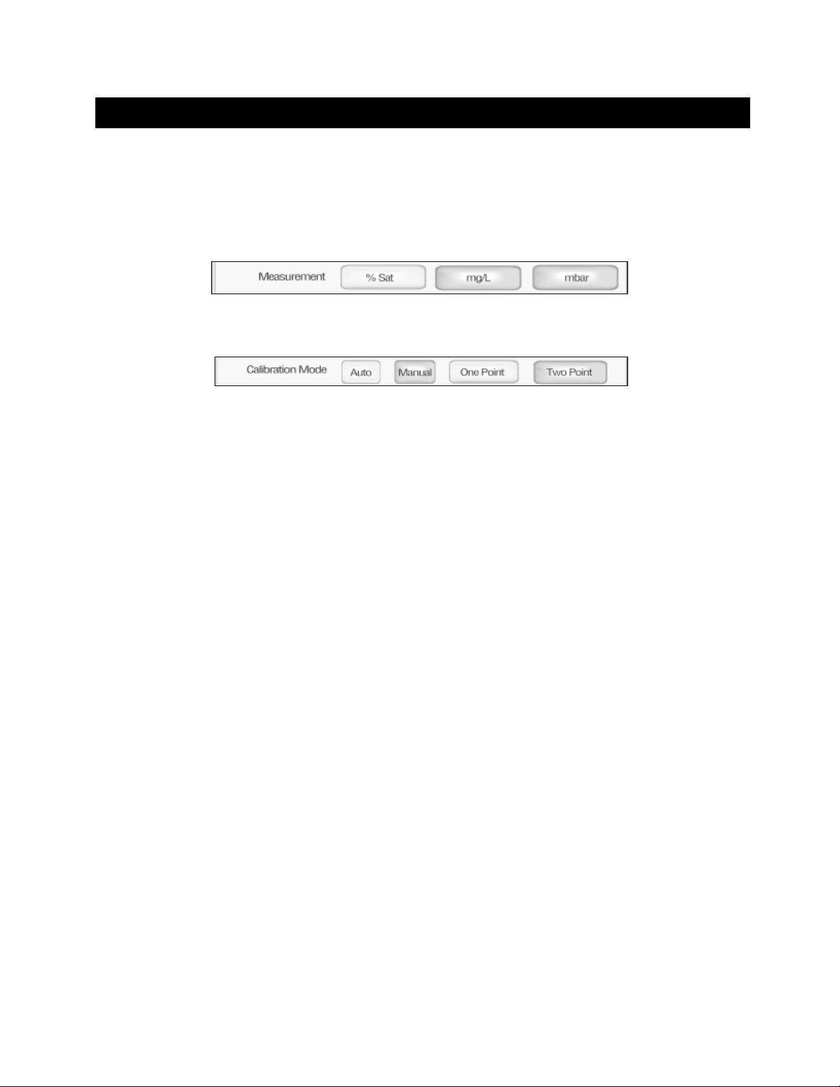
• In DO Setup, select the desired measurement unit. In OUR and SOUR setup modes, the measurement
unit cannot be changed.
• In DO Setup, select the Calibration mode options:
% Saturation C alibration Mode Options:
Auto calibration at one point (100 % saturation)
Auto calibration at two points (0 and 100 % saturation)
Manual calibration at one point
mg/L Calibrat ion Mode Options:
Auto calibration at one point (8.26 mg/L)
Auto calibration at two points (0 and 8.26 mg/L)
Manual calibration at one point
mbar Calibration Mode Options:
None (measurement is applied from % saturation standardization)
43
Page 44
Tip: For best results, allow the 13-620-SSP dissolved oxygen
Set Barometer:
The XL600 has a n interna l bar om etric pres sure s ensor in bo th the au to and manual calibration m ode. Pr ior
to calibration you ma y wish to verify the actual barometric pres s ure. If this valu e is dif f er ent than the c ur ren t
barometric pressur e displayed, you can calibra te the internal barom eter. See below to set the barometer.
DO NOT use the barom etric pr essur e issued b y the weather s ervice sinc e this va lue is typica ll y adjusted to
sea level.
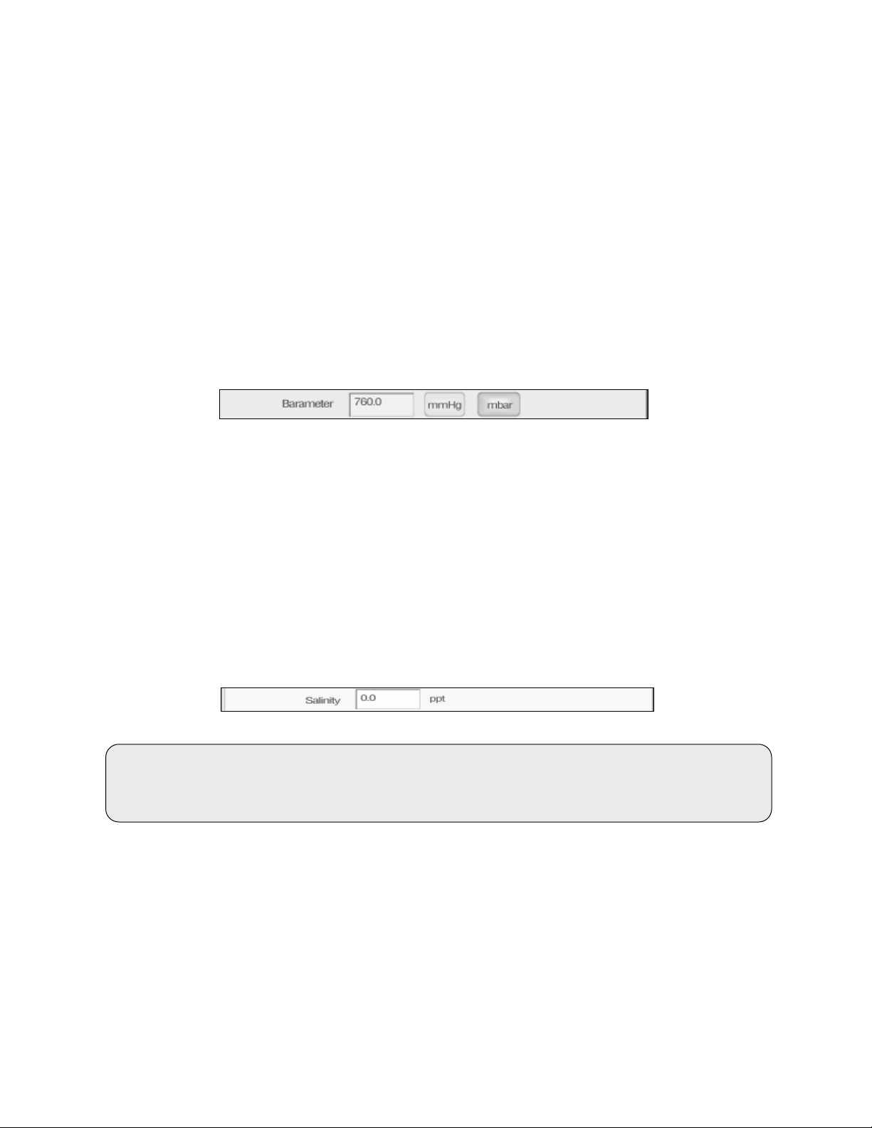
The barometer can be set from 450 to 825 mmHg or 599 to 1099 mbar.
1. Select mmHg or mbar barometric units. The current internal barometric pressure value will
be displayed.
2. Select the value and use the numeric keypad on the screen to enter the actual barometric pressure.
3. Select Enter on the keypad to accept the barometric pressure value and return to the Setup screen.
Set Salinity:
Dissolved salts alter the re lationship bet ween the parti al pressure of ox ygen and the ox ygen concentrat ion
in water. Water containing high le vels of dissolve d salts reduces the solubil it y of dissolved ox yge n in water.
By setting the salinity (in parts per thousand) of your s ample, the XL600 can c ompensate f or the impact of
salinity on th e partial press ure/oxygen co ncentration relat ionship to your sample. T he salinity value can be
adjusted from 0 to 45 ppt (4.5 % dissolved solids).
1. The current salinity value is displayed.
2. Select the value and use the numeric keypad on the screen to enter the salinity of your sample.
3. Select Enter on the keypad to accept the salinity value and return to the Setup screen.
electrode to warm up for at least 10 minutes after connecting i t to the
meter and prior to standardization or measurement.
44
Page 45

One Point Automatic Standardization – % Saturation:
A one point automatic s tandardizatio n for % s aturation assum es the dissolv ed oxygen le vel is at saturation
(100% at 0 ppt salinity, 25.0 °C and 760 mmHg).
1. Power on the XL600, connect the 13-620-SSP probe and allow ≥10 minutes for warm up.
2. Insert DO probe into a BOD bottle filled with 1 inch of water to provide a 100 % relative
humidity environment.
3. From DO % saturation measurement screen, select Standardize.
4. The XL600 will automatically recognize the 100 % saturation standardization value, indicated by a
blinking 100 % beaker icon. The meter will accept readings that are measured between 30 % and
200 % saturation.
5. When STABLE appears, select Confirm. The meter will return to the measurement screen upon a
successful standardization.
Two Point Automatic Standardization – % Saturation:
A two point autom atic stan dardizatio n for % sat uratio n assum es the diss olved o xygen level is at saturation
(100 % at 0 ppt salinity, 25.0 °C and 760 mmHg). The XL600 can be standard ized at 0 % saturation and
100 % saturation. 0% s aturation is requ ired to be the first standardi zation point, foll owed by 100 % as the
second standardization point.
1. Power on the XL600, connect the 13-620-SSP probe and al low ≥10 minutes for warm up.
2. Insert the 13-620-SSP probe into a “zero oxygen solution” to standardize the 0 %. For best results it is
important to allow enough time for the zero oxygen reading to stabilize as low as possible. The value
must be
TIP: to ensure that the value has leveled off to its lowest point, use the “Show graph” feature.
3. From DO % saturation measurement screen, select Standardize.
4. The XL600 will automatically recognize the 0 % sat urat ion st and ar dizat io n value, indic at ed b y a
blinking 0 % beaker icon. If 0% is not recognized, check that the standardization mode has been set to
“Two Point” in the DO setup menu.
5. When STABLE appears, select Confirm to complete the 0 % standardization.
6. Rinse the 13-620-SSP probe very well to remove any trace of zero oxygen solution. Residual zero
oxygen solution will dram atically affect the 100 % standardization if carried over.
7. Insert DO probe into a BOD bottle filled with 1 inch of water to provide a 100 % relative
humidity environment.
8. The XL600 will automatically recognize the 100 % saturation standardization value, indicated by a
blinking 100 % beaker icon. The meter will accept readings that are measured between 30 % and
200 % saturation.
9. When STABLE appears, select Confirm. The meter will return to the measurement screen upon a
successful standardization.
below 5 % to accept the standardization.
45
Page 46

One Point Automatic Standardization – mg/L:
A one point automatic standardization for mg/L assumes the dissolved oxygen level is at saturation
(8.26 mg/L at 0 ppt salinity, 25.0 °C and 760 mmHg).
1. Power on the XL600, connect the 13-620-SSP probe and al low ≥10 minutes for warm up.
2. Insert DO probe into a BOD bottle filled with 1 inch of water to provide a 100 % relative
humidity environment.
3. From DO mg/L measurement screen, select Standardize.
4. The XL600 will automatically recognize the 8.26 mg/L standardization value, indicated by a blinking
8.26 mg/L beaker icon. The meter will accept readings that are measured between ±50 % of the factory
default value.
5. When STABLE appears, select Confirm. The meter will return to the measurement screen upon a
successful standardization.
Two Point Automatic Standardization – mg/L:
The XL600 can be standardized at 0 mg/L and 8.26 mg/L (at 0 ppt salinity, 25.0 °C and 760 mmHg).
0 mg/L is required to be the first standardization point, followed by 8.26 mg/L as the second
standardization point.
1. Power on the XL600, connect the 13-620-SSP probe and al low ≥10 minutes for warm up.
2. Insert the 13-620-SSP probe into a “zero oxygen solution” to standardize the 0 mg/L. For best results it
is important to allow enough time for the zero oxygen reading to stabilize as low as possible. The value
must be
TIP: to ensure that the value has leveled off to its lowest point, use the “Show graph” feature.
3. From DO mg/L measurement screen, select Standardize.
4. The XL600 will automatically recognize the 0 mg/L standardization value, indicated by a blinking 0 mg/L
beaker icon. If 0 mg/L is not recognized, check that the standardization mode has been set to “Two
Point” in the DO setup menu.
5. When STABLE appears, select Confirm to complete the 0 mg/L.
6. Rinse the 13-620-SSP probe very well to remove any trace of zero oxygen solution. Residual zero
oxygen solution will dramatically affect the 8.26 mg/L standardization if carried over.
7. Insert DO probe into a BOD bottle filled with 1 inch of water to provide a 100 % relative
humidity environment.
8. The XL600 will automatically recognize the 8.26 mg/L standardization va lu e, ind icated b y a blink ing
8.26 mg/L beaker icon. The meter will accept readings that are measured between ±50 % of the factory
default value.
9. When STABLE appears, select Confirm. The meter will return to the measurement screen upon a
successful standardization.
below 1 mg/L to accept the standardization.
46
Page 47

One Point Manual Standardization – mg/L or % Saturati on:
A one point automatic standardization for mg/L assumes the dissolved oxygen level is at saturation
(8.26 mg/L or 100 % at 0 ppt salinity, 25.0 °C and 760 mmHg).
1. Power on the XL600, connect the 13-620-SSP probe and al low ≥10 minutes for warm up.
2. Insert DO probe into a BOD bottle filled with 1 inch of water to provide a 100 % relative
humidity environment.
3. From DO mg/L or % measurement screen, select Standardize.
4. The XL600 will blink a beaker icon without a value before the keypad pops up. Enter the desired
mg/L or % value then select Enter.
5. When STABLE appears, select Confirm. The meter will return to the measurement screen upon a
successful standardization.
47
Page 48
34. BOD OPERATION
The BOD (Biological Oxygen Demand) Setup screen present offers options to control the operating
parameters of the m eter. The meter is factor y set with regard to these op tions, and is read y for use under
most circumstances. The BOD setup screens are virtually identical to the DO setup screens with
exceptions noted. The previous section on the DO Setup will guide you through the various options
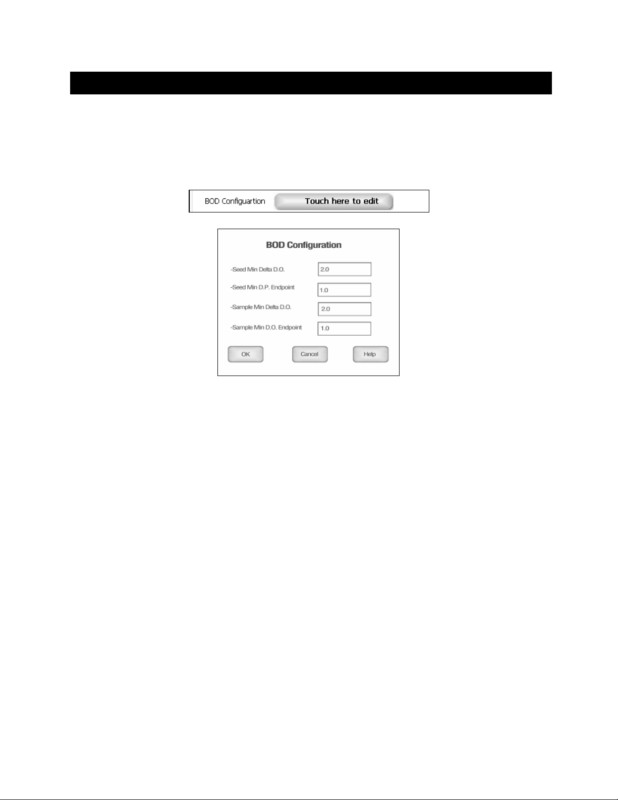
available in the BOD setup mode. The main difference is that BOD offers a configuration to edit n the
setup mode:
The BOD configuratio n screen allows configuration of the BOD seed minimum Delta DO, seed minimum
DO endpoint, sample m inimum Delta DO and sam ple minimum DO endpoint. Ea ch can be set from 0.0 to
60.0 using the keypad.
The Seed Minimum Delta DO r efers to the diff erence between the in itial and final DO measurements for
the seed used. If the delta is less than the minimum value entered, that BOD value will not be used to
calculate seed values. The seed must exhibit a final DO value greater than the Seed Minimum DO
Endpoint value entered. If not, it will not be used in computing seed values.
The Sample Minimum Delta DO refers to the difference between the initial and final value DO
measurements of the s ample. If the diff erence is less than the m inimum value ent ered, that BOD v alue will
not be used to calculate averag e BOD measurements. The sam ple must exhibit a final DO value great er
than the Sample Minimum DO Endpoint value entered. If not, it will not be used in computing a verage
BOD values.
48
Page 49
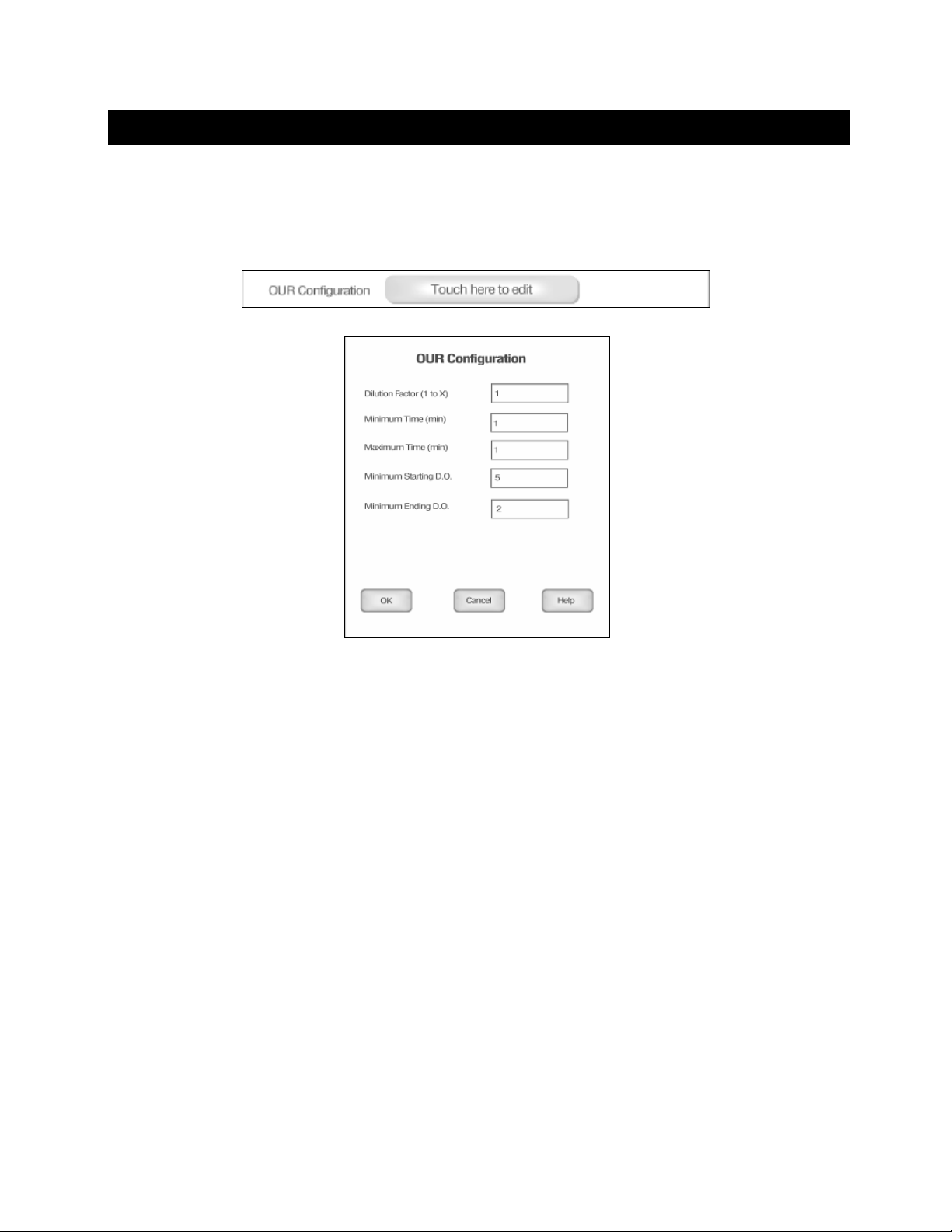
35. OUR OPERATION
The OUR (Oxygen Uptake Rate) Setup screen present offers options to control the operating parameters of
the meter. The meter is factory set with regard to these options, and is ready for use under most
circumstances. The OUR setup screens are virtually identical to the DO setup screens with exceptions
noted. The previous section on the DO Setup will guide you through the var ious options available in t he
OUR setup mode. The main difference is that OUR offers a configuration to edit n the setup mode:
The OUR configuration allows you conf igure the OUR dilution f actor, m inimum time in m inutes for the test,
maximum time in minutes for the test, minimum starting DO and minimum Ending DO.
Dilution factor can be set f rom 1 to 25, if no dilu tio n was required us e a factor of 1. Minimum t ime s hould be
less than the maximum time f or the test (10 character lim it for time in minutes). Minimum starting DO can
be set from 5 to 60. Minimum ending DO can be set from 0 to 60.
49
Page 50
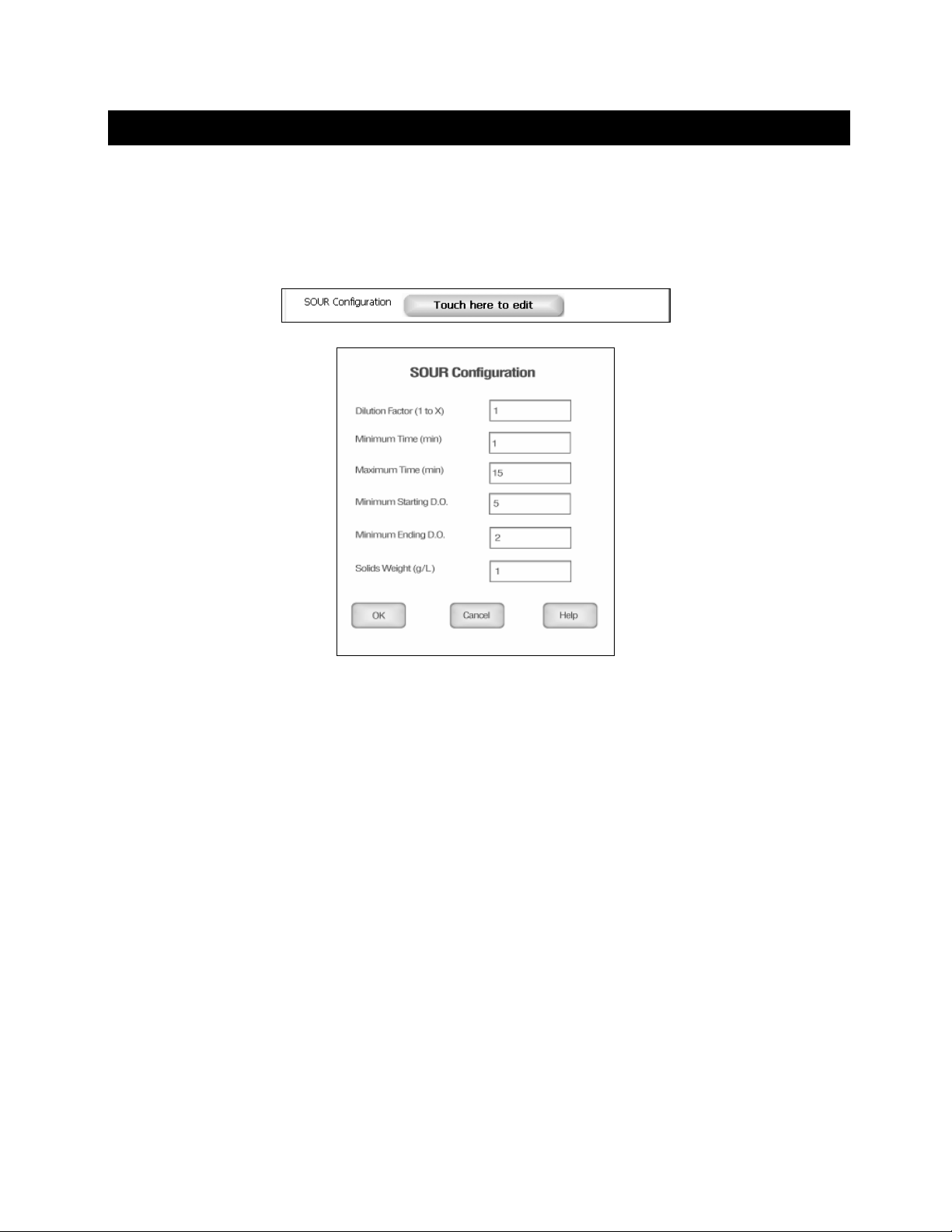
36. SOUR OPERATION
The SOUR (Specific Oxygen Uptake Rate) Setup screen present offers options to control the operating
parameters of the m eter. The meter is factor y set with regard to these op tions, and is read y for use under
most circumstances. The SOUR setup screens are virtually identical to the DO setup screens with
exceptions noted. The previous section on the DO Setup will guide you through the various options
available in the SOUR s etup mode. The main dif ference is that SOUR off ers a configuration to e dit n the
setup mode:
The SOUR screen allows you configure the SO UR dilution factor, minimum time in minutes for the test,
maximum time in minutes for the test, minimum starting DO, minimum Ending DO and solids weight in
grams per liter.
Dilution factor can be set from 1 to 25, if no dilution was required us e a f ac tor of 1. Minimum time should be
less than the maximum time f or the test (10 character lim it for time in minutes). Minimum starting DO can
be set from 5 to 60. Minimum ending DO can be set from 0 to 60.
50
Page 51
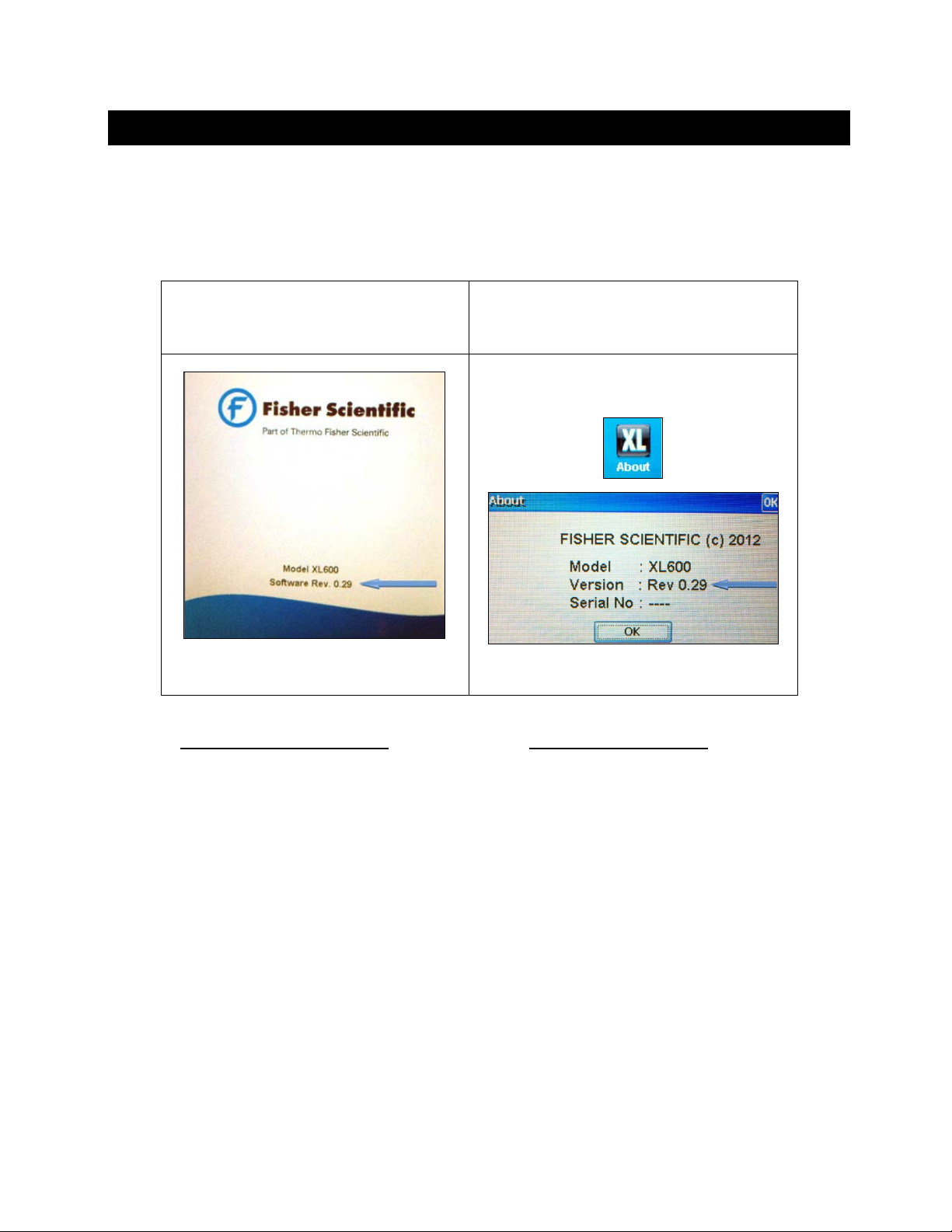
37. FIRMWARE UPGRADE
Software updates for Fisher Scientific accumet® XL150, XL200, XL250, XL500, & XL600 series may
become available. Foll ow the procedure outline d in this section to download a nd install updated soft ware
for your instrument. Pleas e read the entire proc edure before star ting. Note: this proced ure will erase all
data in your instrument to the factory default conditions – save any critical data before upgrading.
1) Determine the software version that is used by your instrument by either;
Observing the temporary display
screen during power on sequence
2) Check
newer software is available for your instrument. Download the update or request the new software to be
emailed to you as an attachment.
www.fishersci.com/accumet or send an email to [email protected] to determine if
Selecting the “About XL” icon
51
 Loading...