

Page 1
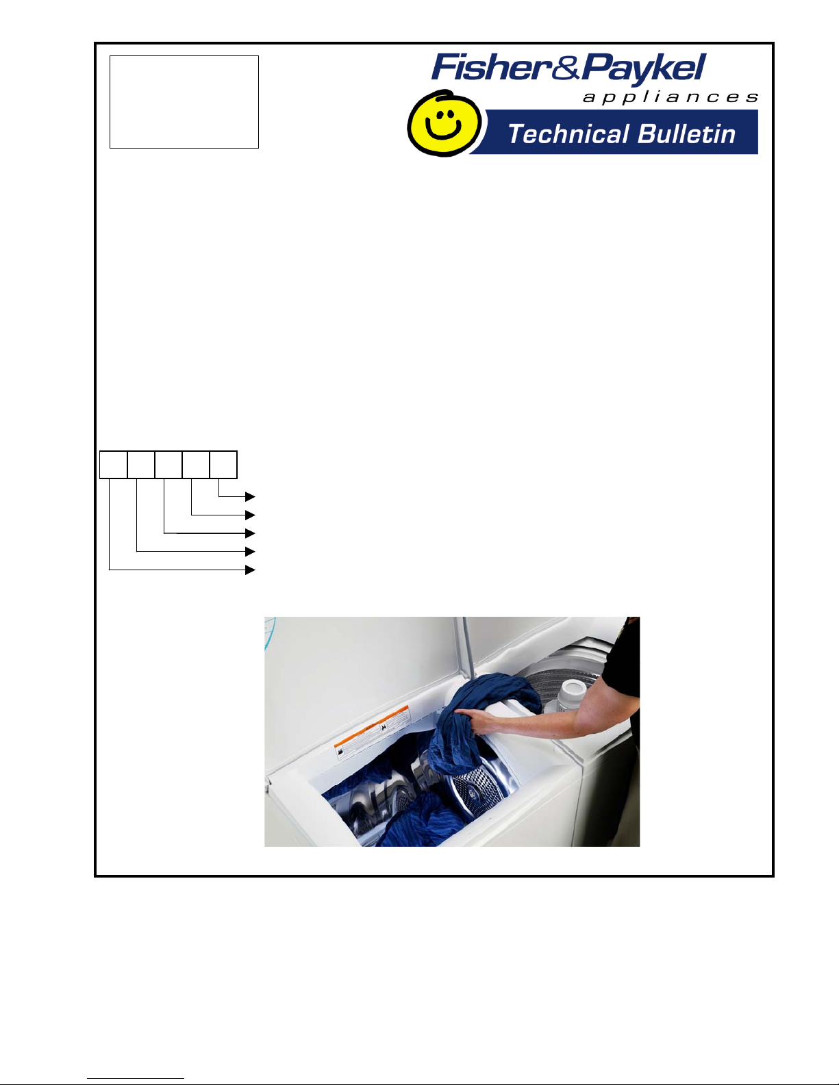
NZ = New Zealand
AU = Australia
ROW = International Markets
USA = United States of America & Canada
GB or UK = Great Britain & Ireland
EU = Europe
TW = Taiwan
JP = Japan
DR019
AUGUST 2004
Fisher & Paykel Appliances Ltd
78 Springs Road, East Tamaki, PO Box 58-732, Greenmount,
Auckland, New Zealand, Ph: 09 273 0600, Fax: 09 273 0656
Fisher & Paykel Customer Services Pty Ltd
A.C.N. 003 3335 171, 19 Enterprise Street, Cleveland, QLD 4163
PO Box 798, Cleveland, QLD 4163, Ph: 07 3826 9100, Fax: 07 3826 9164
Fisher & Paykel Appliances
150 Ubi Avenue 4, Sunlight Building #02-00, Singapore 408825
Ph: 6547 0100, Fax: 6547 0123
Fisher & Paykel Appliances Inc
27 Hubble, Irvine, California, CA92618, USA,
Ph: 949 790 8900, Fax: 949 790 8911
Fisher & Paykel Appliances Ltd UK
Pheasant Oak Barn, Hob Lane, Balsall Common, Warwickshire, CV7 7GX, UK
Ph: 44 1676 531 770, Fax: 44 1676 531 771
COPYRIGHT © FISHER & PAYKEL LTD 2004
Dryers
New Model Introduction – SmartLoad™ Dryer
MARKETS: USA
MODELS: DEGX1, DGGX1
ACTION: We are pleased to announce the release of the
SmartLoad™ top-loading dryer into the U.S. market.
There are two model variations:
DEGX1 - Electric, product code 96010
DGGX1 – Natural Gas, product code 96011
Model Identification
MANUALS: The following manuals can be downloaded
from CoolBlue World.
Note: We have included the Service Summary with this
bulletin.
Description Part Number
Parts Manual 517761
Service Manual 517760
Installation Manual – Electric 395217A
Installation Manual – Gas 395520A
Service Summary (Gas and Electric) 395453B
User Guide 395216
IMPORTANT: Please
read this bulletin and
pass on to others in
your organisation.
D
E
G
X 1
Series
Size
Feature Level
Heating Type (E = Electric, G = Gas)
Product Type (Dryer)
Page 2

Page 3
This information is intended for use by individuals possessing adequate experience of servicing electrical,
electronic, gas and mechanical appliances. Any at tempt to repair a major appliance may result in personal
this information, nor can it assume any liability in connection with its use.
IF A FAILURE OCCURS
the operation is stopped, and a fault code
DIAGNOSTIC MODE
the Last Fault Option
To Select DIAGNOSTIC MODE – Last Fault
Turn the power supply to the dryer on.
while you momentarily press the Power
The dryer is now in diagnostic mode.
to read the Last Fault Option. For other
(Drying)
(Damp)
(Dry)
(Extra Dry)
(Cool Down)
Value
4
Refer to Service Manual for
The motor control module heat source
4.
IMP O RTA NT S AF E TY N OTI C E
Pressing its POWER button to turn the dryer off, does not disconnect the dryer from the power supply, even
though the lights on the dryer control panel are off. Consequently, all terminals and internal parts should be treated
If grounding wires, screws, straps, clips, nuts or washers
Page 4
Temperature more than 70˚C (158˚F) at
the temperature sensor circuit.
40˚C (104˚F) = 5k
Temperature less than -10˚C (14˚F) at
24 Volt Supply Measurement Error
there is continuity through these, replace
the sensor module.
the lid lock should be between 50
and
the sensor module.
through the drum, lter and through the
thermostat.
4.
4.
turned on, replace the sensor module.
DISASSEMBLY
WARNING
Always disconnect the mains power supply
the console. The console can be tilted
damage while in transit by using the special
top deck to cabinet.
Tilt top deck upwards towards the rear
the base panel and lift the cabinet front
this appliance call:
TOLL FREE 1 888 9 FNP USA
27 Hubble
Page 5
6 5 24 3 1
CONDUCTIVITY
54 6
CONDUCTIVITY
EXHAUST
1
GRAB
DOOR
LOCK
LID
53 4 6 7 8
32 4 5 61
M
POWER MODULE
DISPLAY
1 1 12 3 2 22 3
(WHITE)
24V
MOTOR
12
CONTROL
3 2 156 4
AUTO RS
THERM
MOTOR
5 3 1
PHASE / LINE 1
USA-NEUTRAL
1 2 3 4
MOTOR
CONTROL MODULE
(Component side)
DISPLAY
MODULE
LID LOCK
SENSOR
CONTACTS
MODULE
ELECTRIC ELEMENT (240V, 5kW)
PHASE / LINE 2
EARTH / GROUND
T
1.4kW
3.6kW
MOTOR (3 PHASE)
EXHAUST
TEMPERATURE
SENSOR
DOOR
GRABBER
ACTUATOR
TERMINATION
FOR ELECTRIC HEATER
MODELS ONLY
T
BLUE
BLACK
YELLOW
VIOLET
ORANGE
WHITE
YELLOW
VIOLET
RED
RED
BLACK
BLACK
VIOLET
IEC-SAFETY EXTRA LOW VOLTAGE / UL - CLASS
2
SENSOR
YELLOW
(BROWN)
(BLUE)
SENSOR MODULE
(Component side)
LENS POSITION
(Component side)
MAINS/RELAY
A
RELAY
B
FACTORY
USE ONLY
0V
TX/RX
5V
NC
CLK
DATA
STR
0V
+5V
MANUAL
RESET
T
0V
+5V
+24V
TACHO
NC
TX/RX
KEY
(BLACK)
C
B
A
54 61 2 3
7
GREEN
TRANSFORMER 240V, 60Hz
ORANGE
ORANGE
VIOLET
VIOLET
RED
RED
P
S1
S2
VIOLET
321
WHITE
Page 6
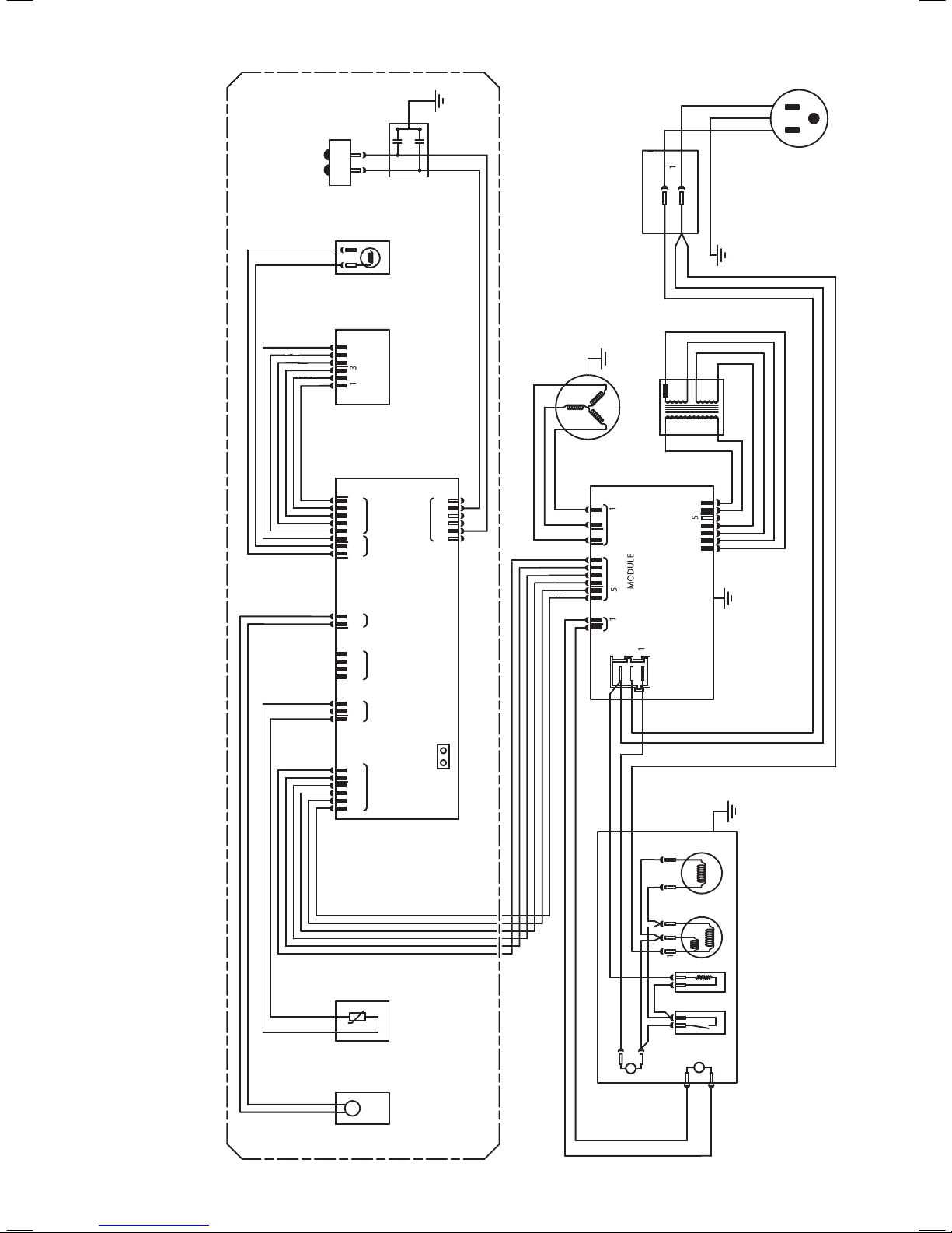
6 5 24 3 1
54 6
CONDUCTIVITY
EXHAUST
1
53 4 6 7 8
M
POWER MODULE
DISPLAY
1 1 12 3 2 22 3
(WHITE)
24V
THERM
1 2 3 4
LID LOCK
SENSOR
T
TEMPERATURE
TERMINATION FOR GAS HEATER
T
SENSOR
YELLOW
(BROWN)
(BLUE)
SENSOR MODULE
(Component side)
LENS POSITION
FACTORY
USE ONLY
0V
TX/RX
5V
NC
CLK
DATA
DATA
DATA
STR
STR
0V
0V
0V
+5V
+5V
FLAME DETECTOR
IGNITOR
PRIMARY VALVE
PRIMARY VALVE
SECONDARY VALVE
SECONDARY VALVE
0V
+5V
+5V
+24V
+24V
+24V
TACHO
TACHO
TACHO
NC
NC
NC
NC
TX/RX
TX/RX
TX/RX
KEY
KEY
KEY
(BLACK)
TRANSFORMER 120V 60Hz
WHITE
 Loading...