

Page 1

INTEGRATED COLUMNS
RS4621F, RS6121F, RS7621F,
RS6121S & RS7621S models
INSTALLATION GUIDE
NZ AU GB EU
849164C 03.19
Page 2

Page 3
1
1 SAFETY AND WARNINGS
2 INTEGRATED COLUMNS
3 COMPONENTS
4 TOOLS
5 DUAL INSTALL OPTIONS
6 PRODUCT DIMENSIONS AND SPECIFICATIONS
7 CABINETRY OPTIONS
8 CAVITY DIMENSIONS
9 DOOR AND TOE KICK PANEL DIMENSIONS
!0
CUSTOM DOOR PANEL DIMENSIONS
!1
CUSTOM DOOR PANEL INSTALLATION TEMPLATE
!2
DOOR CLEARANCE
!3
ELECTRICAL AND PLUMBING
!4
BEFORE INSTALLATION
!5
CAVITY PREPARATION
!6
WATER AND POWER SUPPLY CONNECTION
CONTENTS
OR
!7
SINGLE INSTALLATION
!8
DUAL INSTALLATION
!9
WATER FILTER INSTALLATION
OR
@0
DOOR PANEL INSTALLATION
(STAINLESS STEEL)
@1
DOOR PANEL INSTALLATION
(CUSTOM)
@2
TOE KICK INSTALLATION
@3
CABINET TRIMS INSTALLATION
@4
DOOR TRIMS INSTALLATION
@5
OPTIONAL — CHANGING OVER DOOR HINGES
@6
FINAL CHECKLIST
IMPORTANT!
SAVE THESE INSTRUCTIONS
The models shown in this installation guide may not be available in all markets and are subject to change at any time. For current details about model and specification availability in your country,
go to our website fisherpaykel.com or contact your local Fisher & Paykel dealer.
Page 4
2
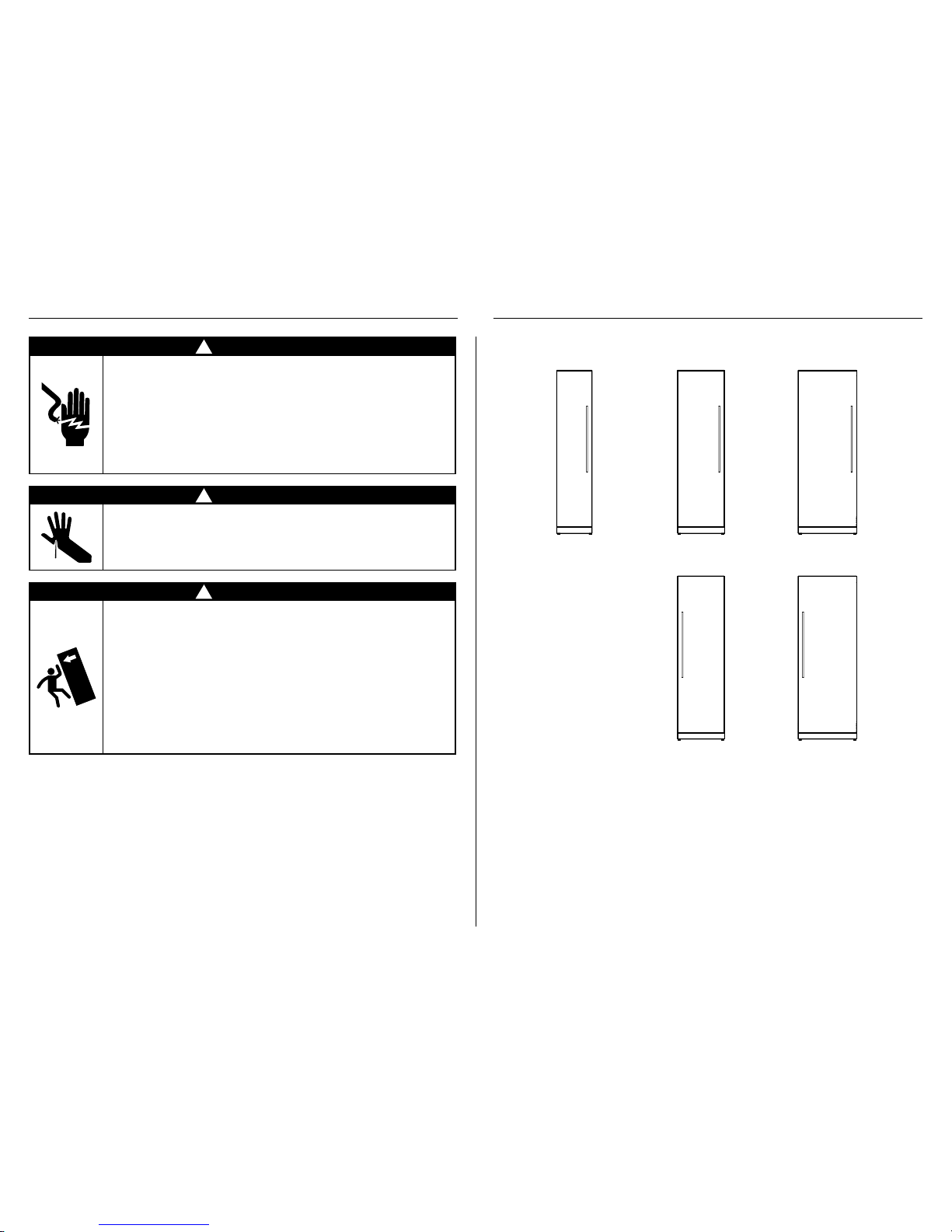
457mm 610mm 762mm
FREEZER
RS4621F RS6121F RS7621F
REFRIGERATOR
RS6121S RS7621S
1 SAFETY AND WARNINGS
!
WARNING!
Electric Shock Hazard
Read and follow the safety and warnings
outlined in this installation guide before
operating this product.
Failure to do so can result in death, electric
shock, fire or injury to persons.
!
WARNING!
Cut Hazard
Take care — panel edges are sharp. Failure to
use caution could result in injury or cuts.
!
WARNING!
This product is top-heavy and must be
secured to prevent the possibility of
tipping forward.
To ensure that the product is stable under
all loading conditions, the anti-tip bracket
and fittings supplied must be installed
according to the following installation steps
by a professional installer.
2 INTEGRATED COLUMNS
Note: Interchangeable door hinges available for each model.
Page 5

3
3 COMPONENTS
Installation kit
Packaged in box located inside the product
Door panel attachmentkit
Side bracket
(6)
Bracket slider
(6)
Side spacer bracket
(6)
For SS door panels:
8Gx16 Mush washer screw (30)
For Custom door panels:
M5x12 Cross-hea d screw (30)
Install fasteners kit
Cabinet depth alignment gauge
(4)
Barbed plug
(2)
8Gx16 Countersunk screw
(7)
Anti-tip bracket assemblykit
Anti-tip bracket
(1)
Masonry plug
(4)
10-12x35mm cross-head screw
(5)
Miscellaneous components
Each supplied separately
Hinge limiting pin
(3)
Air toe kick seal
(1)
Door panel template (double-sided)
(1)
Flow divider cap
(1)
Filter cartridge tool
(1)
Page 6
4
3 COMPONENTS
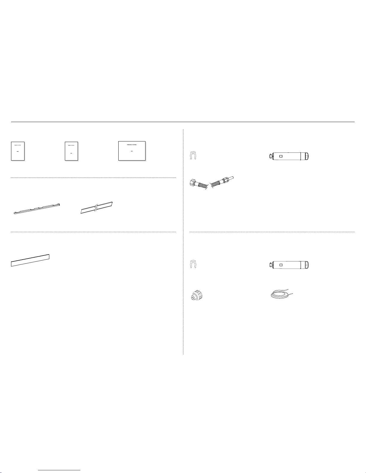
Water filter install kit (for GB & EU only)
(included in MI pack of Freezer models only)
Collet locking clip
(1)
Water filter
(1)
3/4” (19mm) BSP water fitting
(1)
1/4” (6.4mm) plastic tubing
(1)
MI (miscellaneous items) pack
Located inside the product
USER GUIDE
NZ AU
INTEGRATED COLUMNS
RS4621F, RS6121F, RS7621F,
RS6121S & RS7621S models
SERVICE & WARRANTY
SERVICE ET GARANTIE
ΣΈΡΒΙΣ ΚΑΙ ΕΓΓΎΗΣΗ
SERVIZIO E GARANZIA
SERVICE & GARANTIE
HUOLTO JA TAKUU
SERVICE OG GARANTI
保修和维修
服務和保修
INTEGRATED COLUMNS
RS4621F, RS6121F, RS7621F,
RS6121S & RS7621S models
INSTALLATION GUIDE
NZ AU GB EU
849164B 10.18
User guide
(1)
Service & Warranty
(1)
Installation guide
(1)
Water filter install kit (for NZ & AU only)
(included in MI pack of Freezer models only)
Collet locking clip
(1)
Water filter
(1)
1/2 BSP Stainless steel braided hose
with adaptor (1)
Install parts
Supplied and taped to the back of the product
Door panel side extrusion
(2)
Cabinet side trim assembly
(1)
Toe kick install kit
Not supplied and must be purchased separately
Toe kick
(1)
Standard toe kick height is 102mm forstandard stainless steel door panel.
For Custom door panel installation, atoe kick 50-152mm must be fitted
andadjusted accordingly.
An extra bottom grille is required for a50mm toe kick installation.
Page 7
5
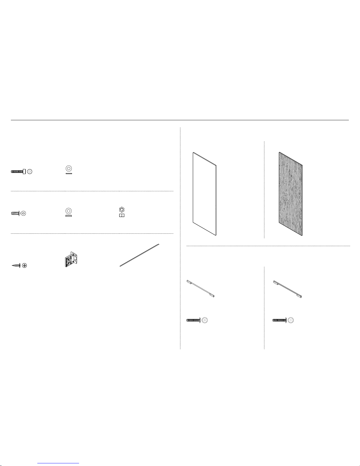
Door panel set
Not supplied and must be purchased separately
Stainless steel door panel set:
(Fisher & Paykel)
Custom door panel set:
Supplied by customers to match their cabinetry.
Applicable to refrigerator
and freezer models.
Applicable to refrigerator
and freezer models.
Dual install joiner kit (CA: 25328)
Used to install two products (refrigerator and freezer) side by side.
Located in Freezer models only. Tapedtotheback of the freezer.
Can be purchased separately through an authorised Fisher & Paykel dealer.
Visitfisherpaykel.com for more information.
Top joiner fastener kit
M5x20 Cap screw
(1)
M5x16x1 Plain washer
(1)
Bottom joiner fastener kit
M6 Washer
843453
M5 Washer
M5 x20
Cap Screw
847984
M6 x 12
Cap Screw
248072
8Gx16
Mush Washer
840371
10 x 50
Dual Lock
M6 Nut
839455
M5 Nut
839107
M6x16 Washer screw
(1)
M6x12x3.2 Plastic washer
(1)
M6 Hex nut
(1)
Top joiner bracket kit
8Gx16 Mush washer screw
(2)
Central spacer
(1)
Centre trim assembly
(1)
3 COMPONENTS
Door handle kit
Not supplied and must be purchased separately. Select between the options below:
Contemporary round handle kit
(CA:25324)
Contemporary square handle kit
(CA:25322)
Contemporary round door handle
(1x)
Contemporary square door handle
(1x)
M5x25 Hex screw
(4x)
M5x25 Hex screw
(4x)
Page 8

6
Top grille assembly
Top (fixed) grille
(1)
Hinge change kit
Not included with the product and must be purchased separately
MODEL LEFT HINGE TO RIGHT HINGE RIGHT HINGE TO LEFT HINGE
RS46 848186 848185
RS61 848188 848187
RS76 848190 848189
Each kit includes: Hinge change assembly (1x), Top (fixed) grille assembly (1x)
Hinge change assembly
Hinge (right or left) top pocket
(2)
K05 top (right or left) adaptor bracket
(1)
Bottom (right or left) adaptor bracket
(1)
Bottom (right or left) hinge bracket
(1)
Supplied tools
Included in installation kit
Spanner 13mm
(1)
Hex key
(1)
Required tools
Not included with product
Powered driver Flathead screwdriver Ruler
Hacksaw Cross-head screwdriver Pencil
Cutter T2 star-head screwdriver
3 COMPONENTS 4 TOOLS
Page 9
7
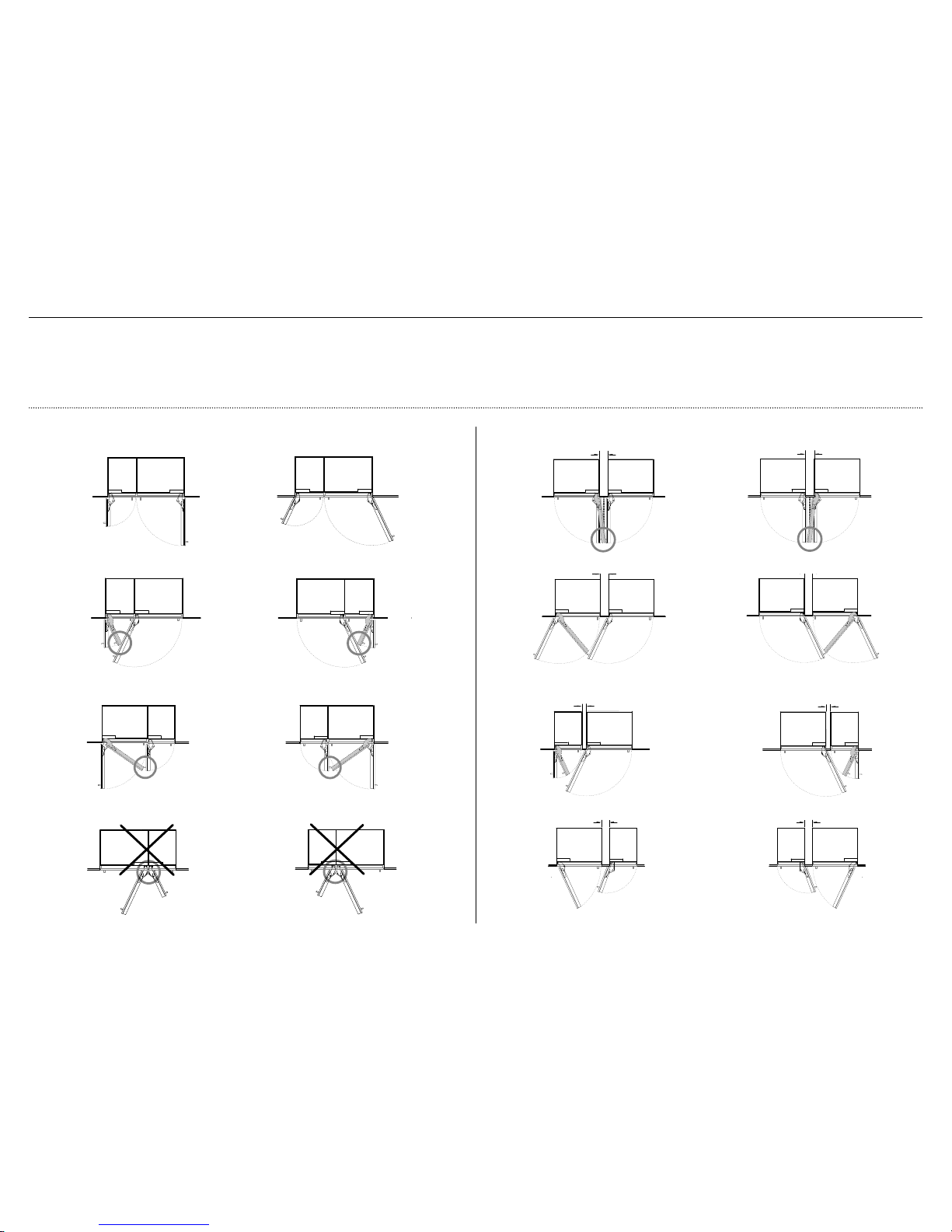
The following are options for dual installation with reference to the door opening range and partition (optional) between two product combinations.
IMPORTANT!
Beware of clashing (circled) when opening the doors. Use a hinge limiting pin to restrict door opening rotation to 90°. Refer to ‘Door Clearance’ (page 15) for more information.
If installing a partition between two products, it must have enough clearance to ensure the doors/handles do not interfere with one another when opening or closing.
NO PARTITION WITH PARTITION
90° DOOR OPENING
115° DOOR OPENING
[FULL ROTATION]
min 100mm
min 100mm
90° DOOR OPENING
115° DOOR OPENING
[FULL ROTATION]
min 100mm
min 100mm
90° DOOR OPENING
115° DOOR OPENING
[FULL ROTATION]
min 60mm
min 60mm
90° DOOR OPENING
115° DOOR OPENING
[FULL ROTATION]
min 100mm
min 100mm
5 DUAL INSTALL OPTIONS
Page 10

8
6 PRODUCT DIMENSIONS AND SPECIFICATIONS
RS46 RS61 RS76
PRODUCT DIMENSIONS mm mm mm
A
Overall height of product 2134 2134 2134
B
Overall width of product 451 603 756
C
Overall depth of product (excluding front door panel) 610 610 610
PRODUCT SPECIFICATIONS
Door clearance 508 660 813
Weight
(including packaging) 118kg 137kg 156kg
Door hinge Hettich K05 Hettich K05 Hettich K05
PROFILE VIEWFRONT VIEW
A
B
C
C
Page 11
9
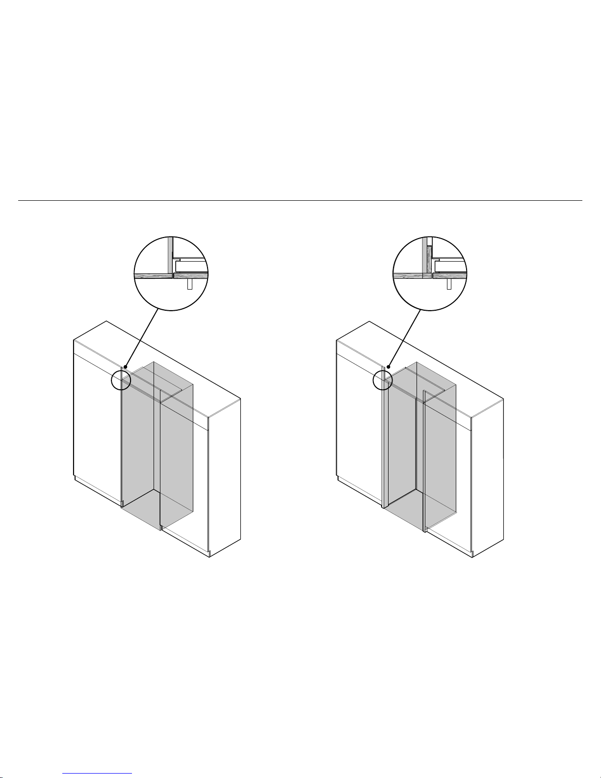
7 CABINETRY OPTIONS
FRAMELESS CABINETRY
Aligns the product/s with the cabinetry
FRAMED CABINETRY
Aligns the product/s with the frame of the cabinetry
Note: Images shown for single install. These options are also applicable for dual install.
Page 12
10
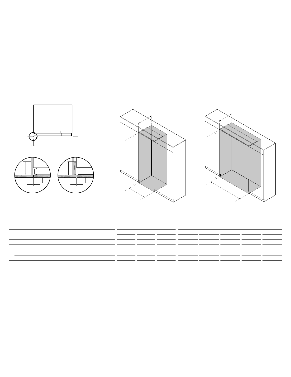
8 CAVITY DIMENSIONS
SINGLE INSTALL DUAL INSTALL
RS46 RS61 RS76 RS46 / RS61 RS46 / RS76 RS61 / RS61 RS61 / RS76 RS76 / RS76
CAVITY DIMENSIONS mm mm mm mm mm mm mm mm
A
Overall height of cavity 2134 2134 2134 2134 2134 2134 2134 2134
b
Overall width of cavity 457 610 762 1067 1219 1219 1372 1524
c
Minimum overall depth of cavity* if the plug is located inadjacent cabinet 635 635 635 635 635 635 635 635
Minimum overall depth of cavity* if the plug is located behind the product 650 650 650 650 650 650 650 650
d
Minimum cabinetry gap clearance from edge of door panels 3 3 3 3 3 3 3 3
e
Minimum required finished return 102 102 102 102 102 102 102 102
* Assumes a door panel thickness of 19mm.
Note: These dimensions are intended for ‘Flush Installation’ only.
E
D
D
Flush with front
of cabinetry
PLAN VIEW
E
D
D
E
D
E
B
A
C
B
A
C
Frameless: finished return
cavity sides and top
Framed: finished return cavity
sides and top
Page 13
11
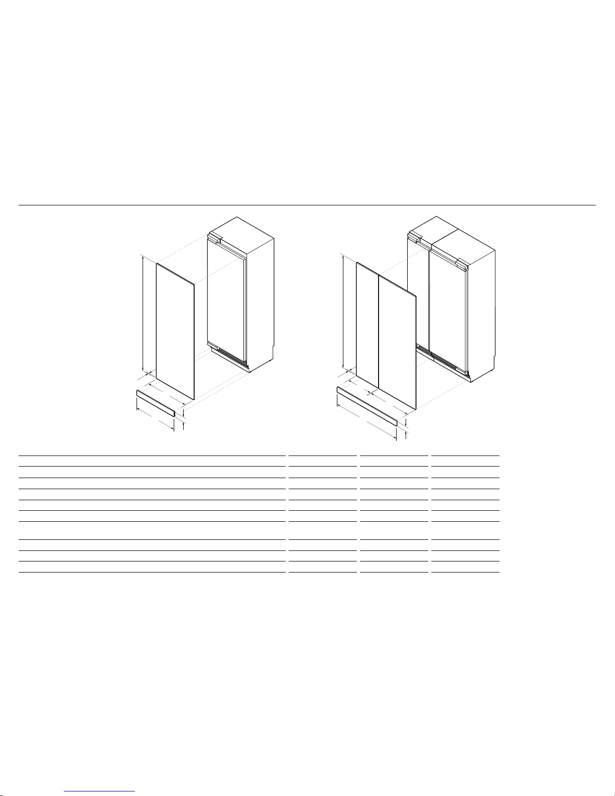
9 DOOR AND TOE KICK PANEL DIMENSIONS
RS46 RS61 RS76
DOOR PANEL DIMENSIONS (STAINLESS STEEL) mm mm mm
A
Height of door panel 2029 2029 2029
B
Width of door panel 451 603 756
C
Depth of door panel (excluding door handle) 19 19 19
DOOR PANEL DIMENSIONS (CUSTOM)*
A
Height of door panel 1978 – 2080 1978 – 2080 1978 – 2080
B
Width of door panel — single install
Width of door panel — dual install
451
452
603
605
756
75 7.5
C
Depth of door panel min 16 – max 25 min 16 – max 25 min 16 – max 25
DOOR PANEL WEIGHT kg kg kg
Maximum weight of Stainless steel/Custom door panel
(including handle/brackets)† 20 25 30
* Custom door panels to be manufactured and fitted by cabinetmaker.
† Door handle kit is available as an optional accessory for both Stainless Steel door panels and Custom door panels and must be purchased separately.
A
C
B
D
E
SINGLE INSTALL
A
C
B
B
D
E
DUAL INSTALL
Page 14
12
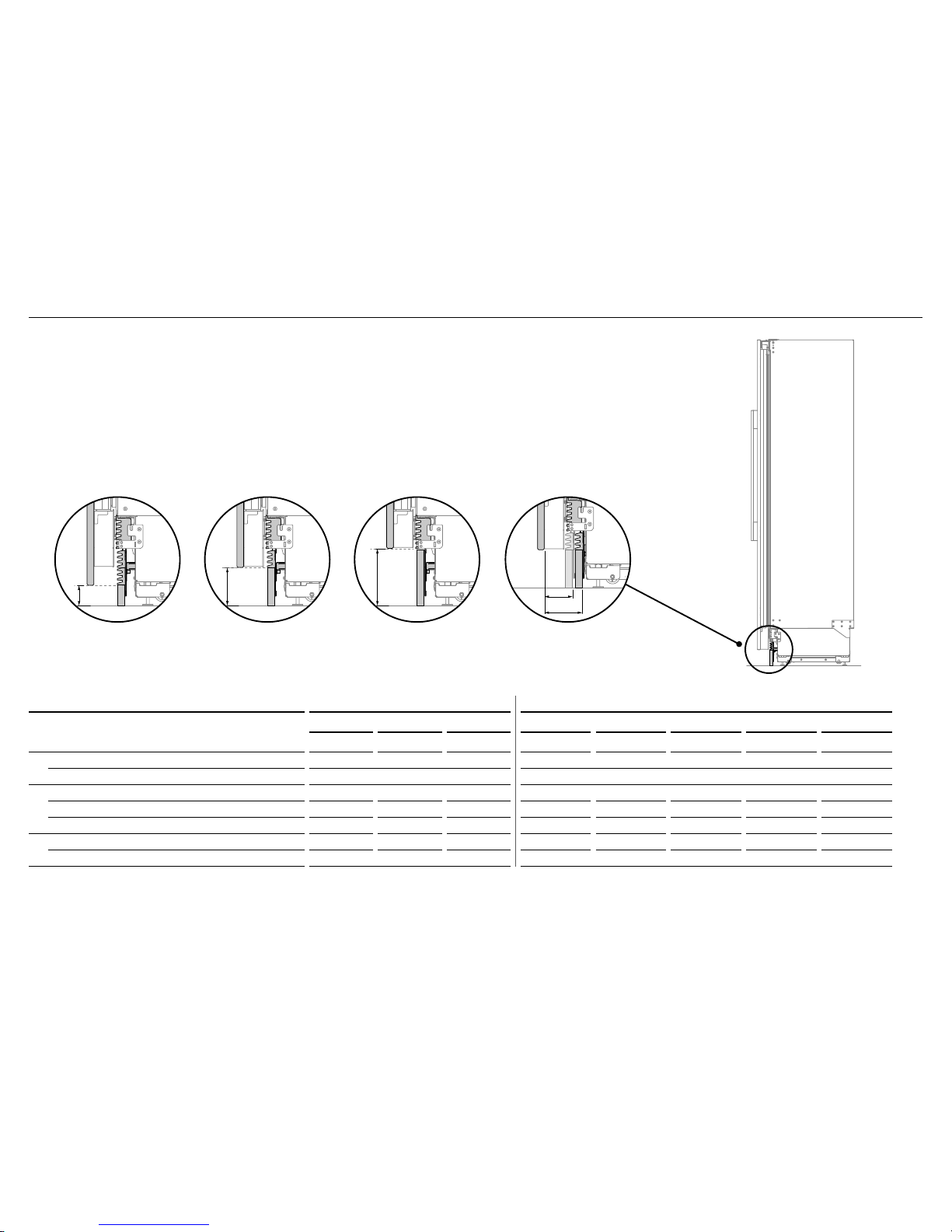
9 DOOR AND TOE KICK PANEL DIMENSIONS
SINGLE INSTALL DUAL INSTALL
RS46 RS61 RS76 RS46 / RS61 RS46 / RS76 RS61 / RS61 RS61 / RS76 RS76 / RS76
TOE KICK DIMENSIONS
mm mm mm
mm mm mm mm mm
D
Width of toe kick
Stainless steel panel/Custom panel 454 606 759 1064 1216 1216 1368 1521
E
Height of toe kick
#
Stainless steel panel 102 102 102 102 102 102 102 102
Custom panel** 50 – 152 50 – 152 50 – 152 50 – 152 50 – 152 50 – 152 50 – 152 50 – 152
F
Depth of toe kick (measured from front of door)
Stainless steel panel/Custom panel 73 – 102 73 – 102 73 – 102 73 – 102 73 – 102 73 – 102 73 – 102 73 – 102
#
Standard toe kick height is 102mm with the optional Stainless door panel. For Custom door panel installation, a custom toe kick 50 – 152mm can be manufactured and fitted by cabinetmaker.
The Custom door panel height needs to be adjusted accordingly.
** Extra lower grilles are required for a 50mm toe kick installation.
102mm toe kick height51mm toe kick height
(with extra lower grille attached)
73 – 102mm toe kick depth
measured from the from
rearof door panel
E
E
E
F
152mm toe kick height
Page 15
13
!0 CUSTOM DOOR PANEL DIMENSIONS
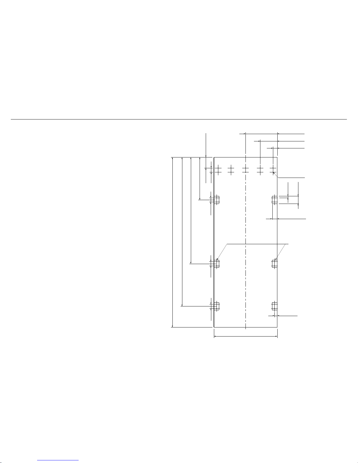
Custom door panel dimensions
Dimensions apply for the preparation and installation of Custom
door panels. For Dwg and Dxf files of the below panel preparation
download the folder on thekitchentools.fisherpaykel.com.
IMPORTANT!
The thickness of the custom door panel can vary provided that the
screws do not penetrate beyond the full depth of the door panel.
Refer to ‘Door panel dimensions (Custom)’ table on page 10 for
thickness limitations of door panel.
Measurements of screw hole locations can vary depending on the
height of toe kick 50 – 152mm.
33mm
60mm
22mm x Ø2mm
756mm
20mm
90mm
51mm
203mm
378mm
127mm
50mm
50mm
508mm
1270mm
1778mm
1978 – 2080mm
Do not place handle holes in
marked areas to avoid clashing
with panel attachment brackets
RS76
50mm50mm
Page 16
14
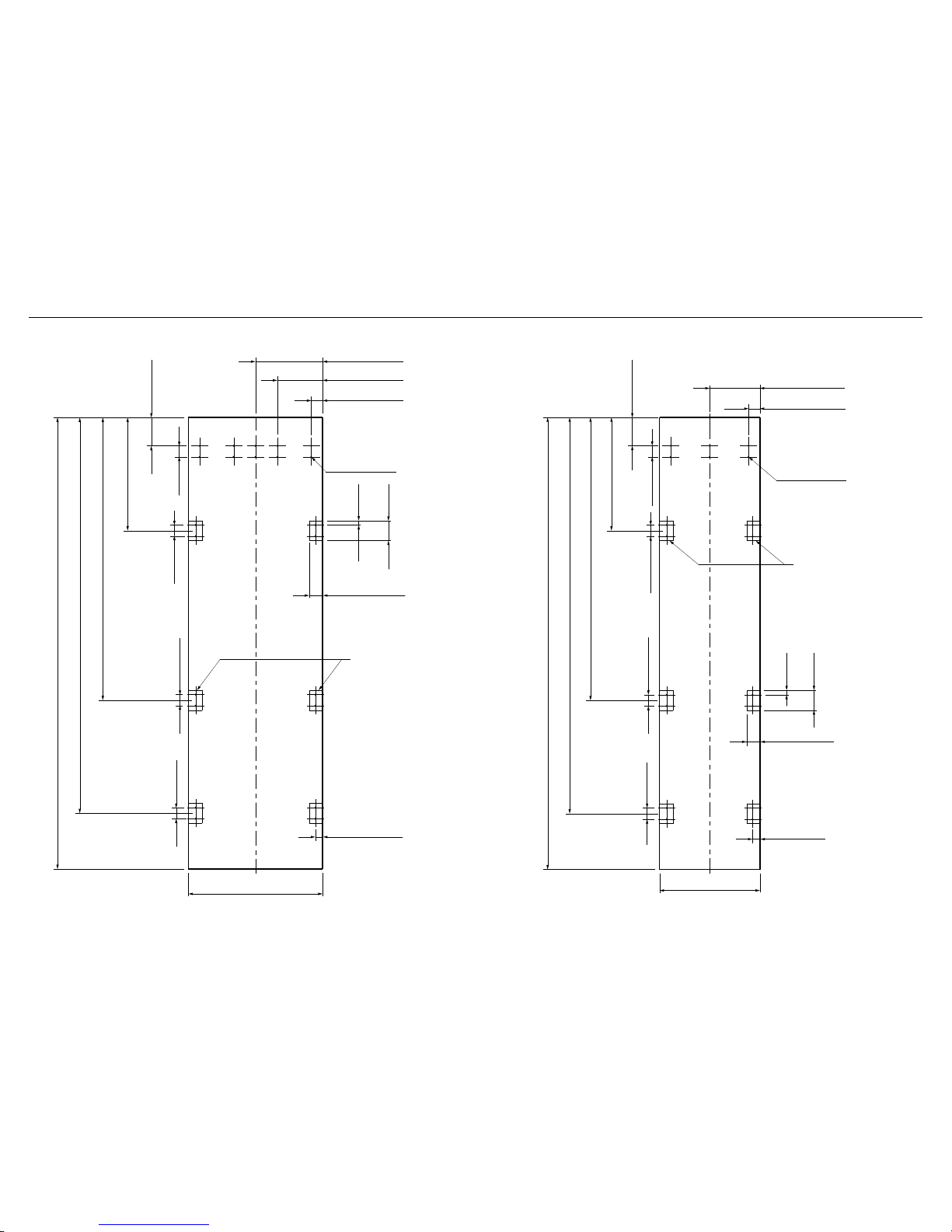
!0 CUSTOM DOOR PANEL DIMENSIONS
603mm
33mm
50mm
50mm
50mm
50mm
1978 – 2080mm
1778mm
1270mm
508mm
127mm
Do not place handle holes in
marked areas to avoid clashing
with panel attachment brackets
51mm
203mm
302mm
RS61
60mm
20mm
90mm
22mm x Ø2mm
1978 – 2080mm
1778mm
1270mm
508mm
127mm
50mm
225mm
51mm
Do not place handle holes in
marked areas to avoid clashing
with panel attachment brackets
33mm
450.8mm
50mm
50mm
50mm
RS46
18mm x Ø2mm
60mm
20mm
90mm
Page 17
15
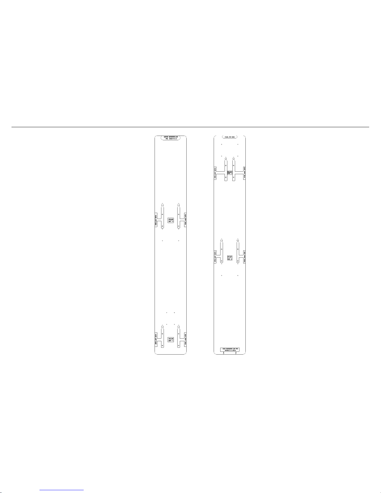
!1 CUSTOM DOOR PANEL INSTALLATION TEMPLATE
This template is a single double-sided sheet used as a
guide to drill screw holes for installing your Custom door
and drawer panels. The actual template is included with
this installation guide.
Refer to 'Door panel installation (Custom)', page 35 for
more information.
PANEL LEFT SIDE PANEL RIGHT SIDE
Page 18
16
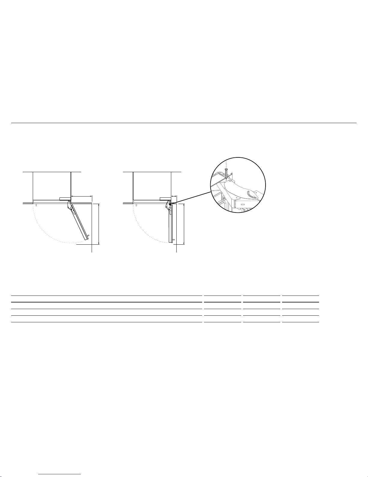
!2 DOOR CLEARANCE
RS46 RS61 RS76
DOOR CLEARANCE DIMENSIONS mm mm mm
A
Depth of door (90° open) measured from front of door 508 660 813
b
Minimum door clearance* to adjacent wall** (115° — full internal access) 292 356 419
c
Minimum door clearance* to adjacent wall** (90° — reduced internal access) 110 110 110
* Measured from front cabinetry edge.
** Does not include the Custom door panels or handles to be manufactured and fitted by a cabinetmaker.
For 90° door swing a hinge limiting bolt is supplied with your
product. This pin fits in the boreholes of the top hinge (Z).
WARNING!
Before opening the doors, ensure that the product is stable.
Follow these steps to avoid risks that can cause serious injury
or death.
1 Open door to 90°.
2 Align the hinge limiting bolt vertically with the bore hole.
3 Insert the pin through the bore hole. Use a hammer to drive
the pin through the hole.
115° DOOR OPENING
(FULL INTERNAL ACCESS)
90° DOOR OPENING
B
AA
C
Wall Wall
Z
Page 19
17
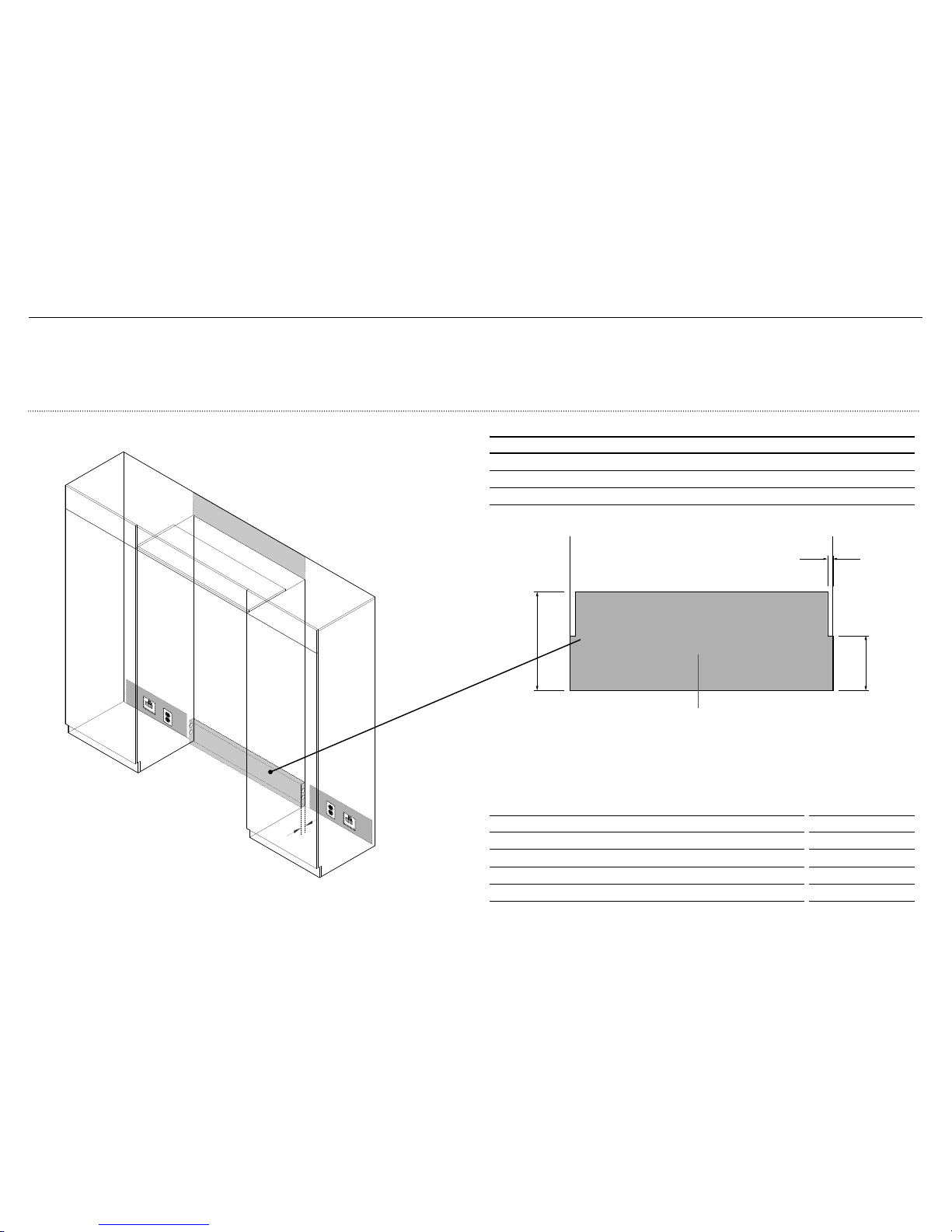
!3 ELECTRICAL AND PLUMBING
Cavity size shown for dual columns installation.
IMPORTANT!
Electrical and water connections for these products must be located in an adjacent area
or unit (cabinet or cupboard) that is easily accessible in case of repair or disconnection.
Note: that once installed, the service technician will NOT remove the product from the
cavity to gain access for repair.
WARNING!
Electric shock hazard! Assume all parts live.
Disconnect supply before servicing and installation.
Floor
A
D
Electrical and water connections must be within this space if located
behind the product and must not protrude from the back wall.
Left side of cavity
REAR OF CAVITY
C
B
1
3
2
1
ELECTRICAL AND PLUMBING CONNECTIONS
1
Recommended location for connections in adjacent area or unit
2
Alternative location for connections above the cavity
3
Alternative location for connections at rear of cavity
ELECTRICAL AND PLUMBING DIMENSIONS mm
A
Overall height of supply area 229
B
Overall depth of supply area 25
C
Width of notch in supply area (both sides) 13
D
Height of sides of supply area (both sides) 127
Note: Dimensions are based on minimum depth of cavity.
IMPORTANT!
Minimum overall depth of cavity should not be less than 650mm if power plug is located
behind the product.
If connections are located behind the product, ensure that you install an isolating switch
to a location that is easily accessible for repair or disconnection.
Page 20
18
!3 ELECTRICAL AND PLUMBING
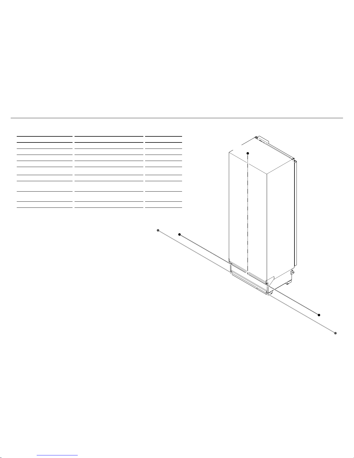
Maximum distance of hose and power cord
ELECTRICAL SPECIFICATIONS FREEZER REFRIGERATOR
Supply 230 VAC, 50 Hz 230 VAC, 50 Hz
Service 10 amp circuit 10 amp circuit
Socket 3-pin earthing-type 3-pin earthing-type
Power cord (excluding plug) 2000mm 2000mm
PLUMBING SPECIFICATIONS FREEZER REFRIGERATOR
Supply 1/2 BSP Stainless steel braided hose
with adaptor
NA
Pressure psi (kPa) min 150psi (22) / max 827psi (120kPa)
@ 68°F (20°C)
NA
Water inlet hose 3000mm NA
* For Freezer models only
Water inlet hose
*— 3000mm
W
ater inlet hose*
— 3000mm
Power cord
— 2000mm
P
ower cord
— 2000mm
BACK SIDE
OF PRODUCT
Power cord — 2000mm
Page 21
19
!4 BEFORE INSTALLATION
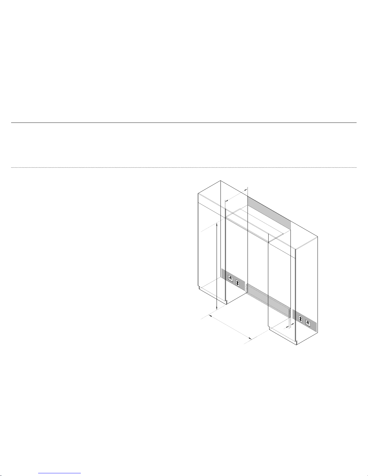
Check the installation location
Check the cabinetry
– Check the dimensions of the cabinetry: height (A), width (B), depth (C),
floor level, finished alcove returns.
– Ensure that the ventilation openings in the cabinetry are clear of obstruction.
Check the power supply connection
– Ensure that there is a separate power socket for each product.
– Avoid sharing the power point with other products to prevent accidental
switching off of the product.
– For power requirements, refer to the information on the serial plate.
– Ensure your product is properly grounded (earthed).
– Connect your product to an electrical supply with the fitted plug and lead.
– If power connection is located behind the product, we recommend to install
an isolating switch to a location that is easily accessible to the user for
repair or disconnection.
– Follow local codes and ordinances when installing the product.
Check the water supply connection (for Freezer models only)
– We recommend connecting the hose to exit at an angle if there is not
enough clearance between the cabinet wall and back of product.
– Fisher & Paykel is not liable for damage (including water damage)
causedby faulty installation or plumbing.
Check your product
– Ensure that your product is the correct model as per your order.
– Ensure that the packaging is not damaged upon delivery.
– Check that the components and install kits are complete.
– You have the option to change the door hinge side of your product from
right hand hinge to left hand hinge or vice versa. A hinge change kit is
required for this installation. Refer to ‘Optional — Changing over door hinges’
for more information.
IMPORTANT!
Ensure your product is not exposed to any heat generating product eg cooktop, oven or dishwasher.
The product has front and rear rollers for moving the product forward and backward. Do not move the product sideways to avoid damaging the rollers or the floor covering/surface.
The product must be installed by a qualified installer, or Fisher & Paykel trained and supported service technician to avoid faulty electrical connection and water leaks.
All connections for water, electrical power and earthing must comply with local codes and ordinances and be made by licensed personnel when required.
Avoid installation of the product/s under a ground fault circuit interrupter (GFCI).
Ensure the product is installed properly. Improper installation that results in product failure is not covered under the product warranty.
C
A
B
Page 22
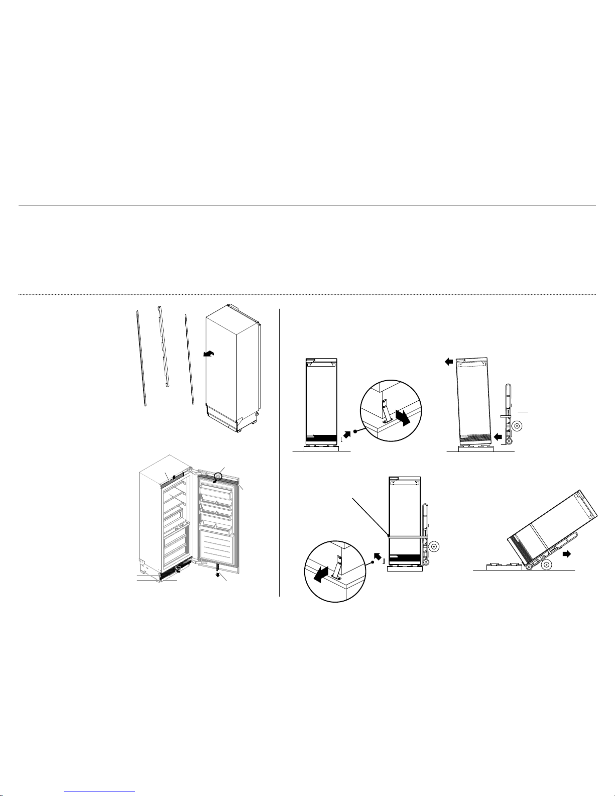
20
!4 BEFORE INSTALLATION
Side trim
assembly
Door panel
side extrusion
Centre trim
assembly
Top trim
Top door
panel
extrusion
Top grille
Bottom grille
Air flow
divider
Unpacking your product
1 Remove the top of the packaging
carton. Cut along the cut lines
and remove the carton and EPS
(Expanded Polystyrene) foam.
2 Remove pre-packed install parts
taped to the back panel of
theproduct.
– Door panel side extrusion
– Side trim assembly
– Centre trim assembly
– Dual install joiner kit
Note: In some models, the install
parts are packed in a box taped
toback panel.
3 Remove/unscrew the
pre-installed parts.
– Top trim
– Top door panel extrusion
– Toe kick mounting plate
– Top grille
– Bottom grille
– Air flow divider
Note: Set aside the screws touse later
when reinstalling the removedparts.
Do not remove the central
magnet housing (circled) from
the top of the product.
IMPORTANT!
Be careful when unpacking to prevent damage to the surface of your product.
Ensure that the product is stable to prevent from tipping over when unpacking.
Do not open the doors to prevent the product from tipping over.
The product is heavy and requires a minimum of 2 persons to unpack and install.
Ensure that the feet of the product are retracted.
If the product is damaged, contact your Fisher & Paykel dealer.
Take note of your model and registration numbers located at the lower right side of the product.
You will need these to request for servicing or repair of your product.
WARNING!
Follow these steps to avoid risks that can
cause serious injury or death.
Keep doors closed until the product has
been moved to its installation location.
magnet housing
Toe kick
mounting plate
4 Restrain the
product tothe
cartwithstraps.
5 Remove the
brackets on the
other side of
theproduct.
Moving your product
1 Remove the brackets from one side of
the product. (Preferably, non-hinged
side of the product).
6 Tilt the product backward
onto the cart.
7 Set aside the pallet and
push the cart to the
installation location.
2 Tilt the product
slightly to the
opposite side.
3 Insert the hand truck
under from the side of
the product where the
brackets were removed.
Do NOT insert the hand
truck to the front or
back of the product.
hand truck
Page 23
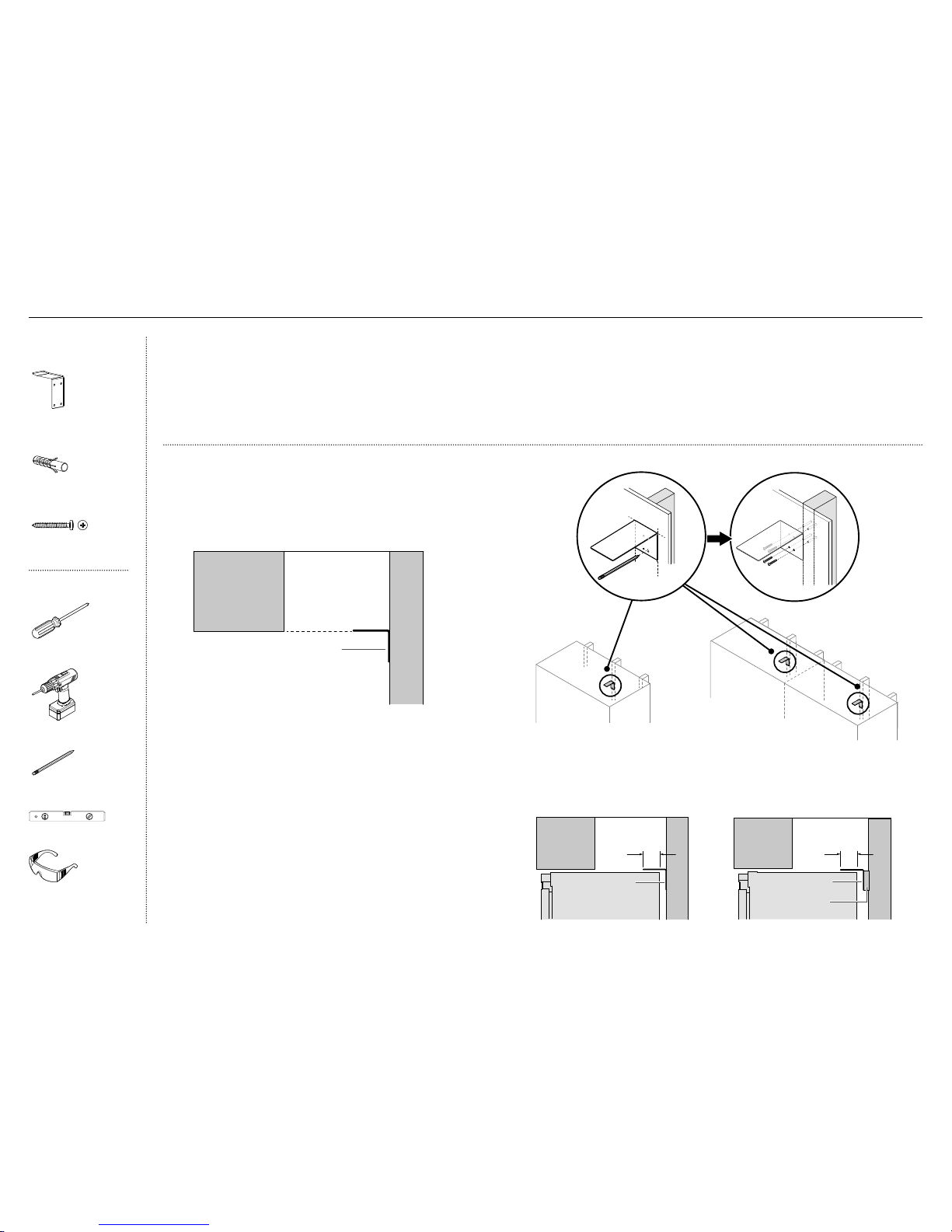
21
!5 CAVITY PREPARATION
min 180mm
E
Bracket
Product Wall
F
Bracket
Spacer
min 180mm
Wall
Product
2 Mark the screw locations of the anti-tip bracket on the wall based
on the most central wall stud (B).
– If there are no wall studs, the bracket can be installed to solid
brick walls with masonry plugs. (It is not recommended for
use with perforated brick or hollow concrete bricks).
3 Drill screw holes to the marked locations.
4 For wooden/plaster board wall installation: Skip to step 5.
For solid wall installation: Hammer 10x30mm masonry plugs (4x)
into the wall until flush.
5 Fix the bracket to the wall with 10-12x35mm pan head screws (4x),
and screw tightly (C).
A
Projection must be from the
alcove return towards the
bottom of the bracket
Bracket
SINGLE INSTALL DUAL INSTALL
C
B
Wall
board
Wall
stud
Anti-tip bracket
assembly kit
Anti-tip bracket
(1)
Masonry plug
(4)
#10x40 cross-head screw
(4)
Tools
Cross-head screwdriver
Powered driver
Pencil
Leveler
Safety glasses
Attaching the anti-tip bracket
1 Project horizontally from the bottom end of the alcove return
towards the back wall (A).
– This will locate the contact surface between the bracket
and the product.
IMPORTANT!
Make sure the bracket overlaps the
product by a minimum 180mm for
a secure hold (E).
IMPORTANT!
Ensure the door of the product is closed when rolling into the
cabinetry.
DO NOT attempt to open the door until the product is fully installed.
The anti-tip bracket and fittings supplied must be fitted to the wall
of the finished enclosure to withstand a 100kg load.
Ensure that the anti-tip bracket is installed correctly to prevent the
possibility of the product tipping forward when the door is open.
WARNING!
Read the following reminders before fastening with masonry plugs and/or
screws to avoid serious injury or possible death:
Ensure the screws avoid electrical, gas and water conduits.
Ensure that the surface where the bracket is fastened can withstand a 100kg load.
Ensure light-weight masonry material such as cinder block and new concrete
(no curing time) are not used in installation.
Do not use metallic materials that may corrode, stain and/or damage the enclosure.
If the minimum 180mm overlap cannot
be achieved, install a solid spacer to
the wall stud behind the bracket (F).
Page 24
22
IMPORTANT!
Old water fittings (hose-sets) should not be reused.
The product includes a stainless braided water line hose.
The shut off valve should be accessible.
Make sure each product is connected to a separate power socket.
WARNING!
The water connection steps below are intended only for the
professional installer.
WARNING — connect to potable drinkable water supply only.
DO NOT install on line pressure above 120psi (827kPa) or below 22psi (150kPa).
DO NOT use on hot water supply (100°F [38°C max.]).
Water fittings kit
(Ice and Water
modelsonly)
Collet lo cking clip
(1)
1/2 BSP Stainless steel
braided hose with
adaptor (1)
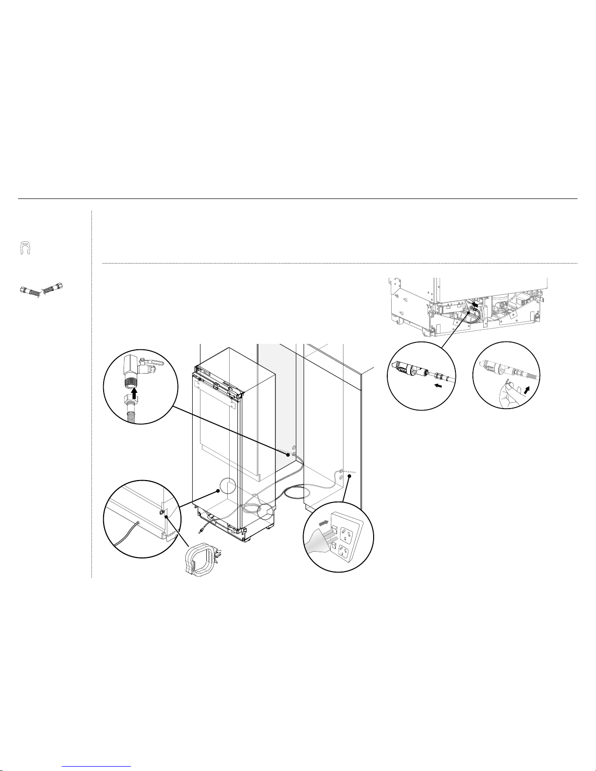
!6 WATER AND POWER SUPPLY CONNECTION (FOR NZ & AU ONLY)
D
C
4 Pull the adaptor end of the braided hose all the way to the
front of the product and insert the tube end of the adaptor
fully into the PRV (C).
5 Secure the connection with a locking clip between the PRV
andhose end of the adaptor (D).
6 Check the connection and open the water supply to testfor leaks.
Note:
– The water supply connection is applicable for freezer
models only.
– For dual installation, do the steps forboth first and
second products.
Connecting to power supply
7 At the back of your product, uncoil the power cord from the
clips (E) and connect to the power supply (230 VAC, 50 Hz) (F).
– You will hear a chime sound when the product is powered
on and automatically goes into ‘Installer (standby) mode’.
– Refer to ‘User guide’ for more details on activating
the product.
Connecting to water supply (for Ice and Water models only)
1 Move the product in front of the cabinetry close enough that you can access
behind for power and waterconnections.
2 Connect one end of the braided water hose to the water tap (A). Flush water
through the hose prior to connection to the product to remove any debris in
the hose.
3 Insert the adaptor end of the hose through a hole at the rear of the plinth (B).
B
Rear view
ofproduct
E
A
F
Page 25
23
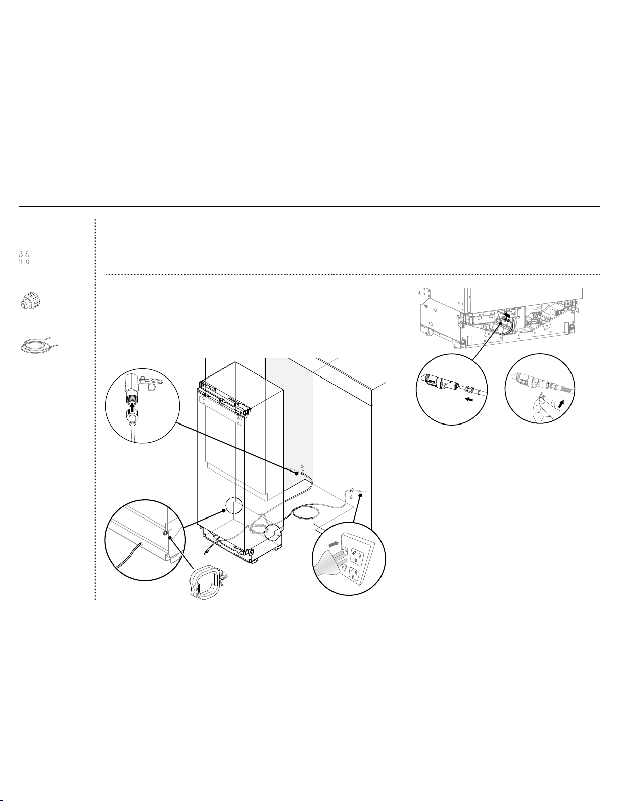
!6 WATER AND POWER SUPPLY CONNECTION (FOR GB & EU ONLY)
IMPORTANT!
Old water fittings (hose-sets) should not be reused.
The product includes a stainless braided water line hose.
The shut off valve should be accessible.
Make sure each product is connected to a separate power socket.
WARNING!
The water connection steps below are intended only for the
professional installer.
WARNING — connect to potable drinkable water supply only.
DO NOT install on line pressure above 120psi (827kPa) or below 22psi (150kPa).
DO NOT use on hot water supply (100°F [38°C max.]).
Water fittings kit
(Ice and Water
modelsonly)
Collet lo cking clip
(1)
3/4” (19mm)
BSP water fitting
(1)
1/4” (6.4mm)
plastic tubing
(1)
D
C
4 Pull the end of the plastic tube all the way to the front of the
appliance and insert 16mm into the PRV (C).
5 Secure the connection with a locking clip between the PRV
andhose end of the adaptor (D).
6 Check the connection and open the water supply to testforleaks.
Note:
– The water supply connection is applicable for freezer
models only.
– For dual installation, do the steps forboth first
andsecondproducts.
Connecting to power supply
7 At the back of your product, uncoil the power cord from the
clips (E) and connect to the power supply (230 VAC, 50 Hz)(F).
– You will hear a chime sound when the product is powered
on and automatically goes into ‘Installer (standby) mode’.
– Refer to ‘User guide’ for more details on activating
theproduct.
Connecting to water supply (for Ice and Water models only)
1 Move the product in front of the cabinetry close enough that you can access behind
for power and waterconnections.
2 Attach the water fitting to one end of the plastic tube and connect it to a water tap
(A). Flush water through the water tube prior to connection to the product to remove
any debris in the hose.
3 Insert the other end of the tube through a hole at the rear of the plinth (B)
F
B
Rear view
ofproduct
E
A
Page 26
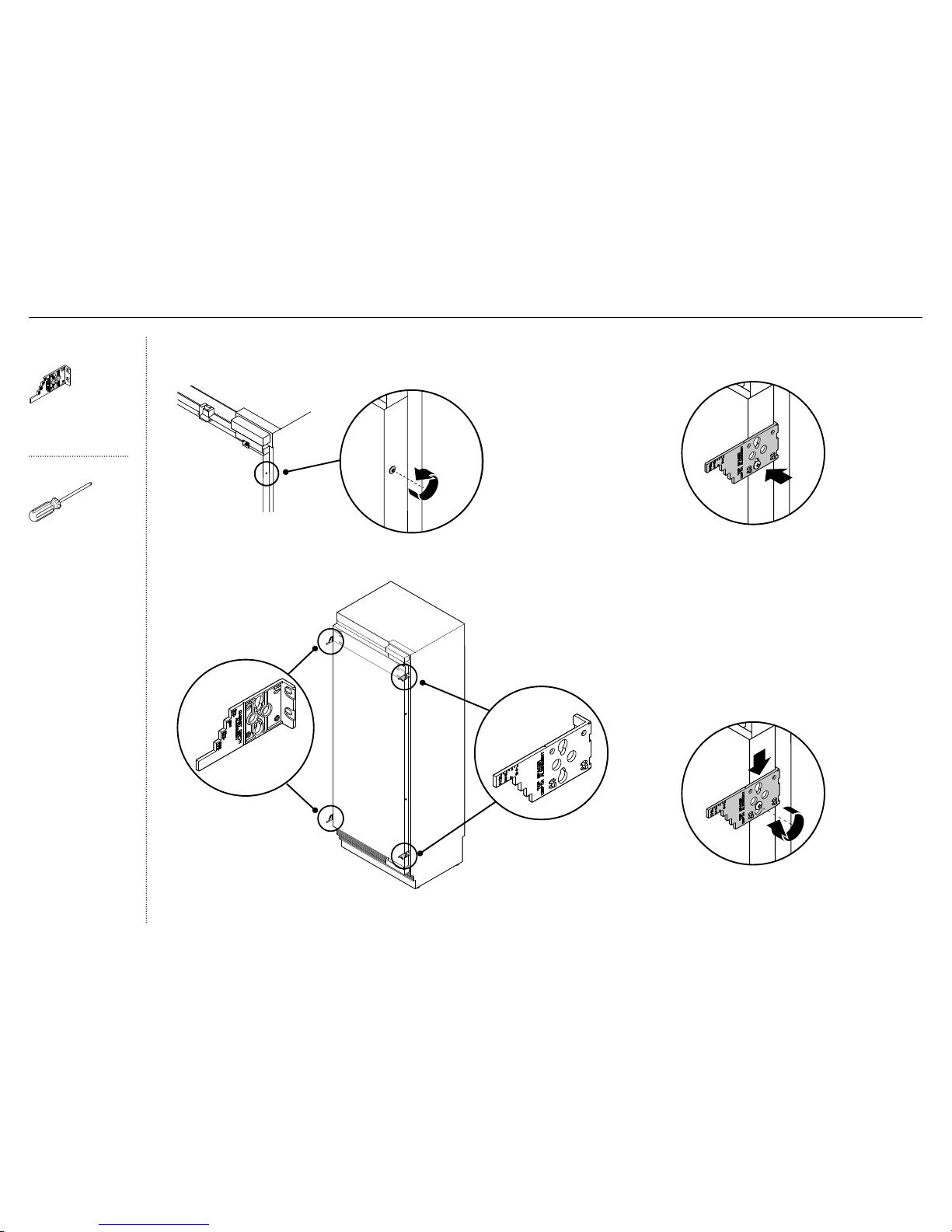
24
Installing depth alignment gauges
Note: The alignment gauges are only temporary and removable after installation.
3 Attach the alignment gauges so that the screw
head passes through the keyhole (C).
4 Lock the position of the alignment brackets
in the keyhole, and tighten the screws just
enough to firmly hold the gauges (D).
C
D
1 Loosen the screws at the right and left,
top and bottom corners of the door (A).
A
2 Locate the alignment gauge to the
screws with the correct orientation (B).
B
B
Install fasteners kit
Cabinet depth
alignment gauge
(4)
Tools
Cross-head screwdriver
!7 SINGLE INSTALLATION
Page 27
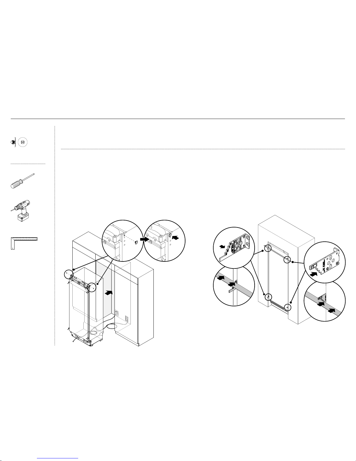
25
IMPORTANT!
Ensure that the hose is not run over when moving the product/s to prevent damage and possible water leaks.
Use low speed, low torque setting when using a powered driver.
Ensure power cord is not damaged during installation.
Aligning the product inside the cabinetry
6 Mark the step on each alignment gauge based on the thickness of
the door panel to be installed to the door (B).
7 Align the marked steps of the gauges flush with the front surface of
the cabinetry.
– Place a ruler on the steps of the alignment gauges to check if
they are in line (C) relative to the thickness of the door panel.
8 Check if the gaps between product and cabinetry side walls are
even on both sides.
Positioning the product inside the cabinetry
1 Coil the water hose flat behind the product.
2 Before rolling the product into the cabinetry, insert a barbed plug into
a large hole on each side of the product to protect the inside of the
cabinetry from being damaged by screws on the sides of the product (A).
3 Roll the product slowly into the cabinetry. Ensure that the water hose is
not run over to prevent damage that can cause a water leak.
4 Continue rolling the product into the cabinetry until the anti-tip bracket
overlaps (min 180mm) the back top surface of the product. Refer to
‘Cavity Preparation’.
5 Check the clearance between the floor and the feet. Ensure the rollers
ofthe product can roll freely on the floor.
C
B
C
B
A
Install fasteners kit
Barbed plug
(2)
Tools
Cross-head screwdriver
Powered driver
(optional)
Ruler
Mark the step on each alignment gauge
based on the thickness of the door panel
to be installed to the door.
!7 SINGLE INSTALLATION
Page 28
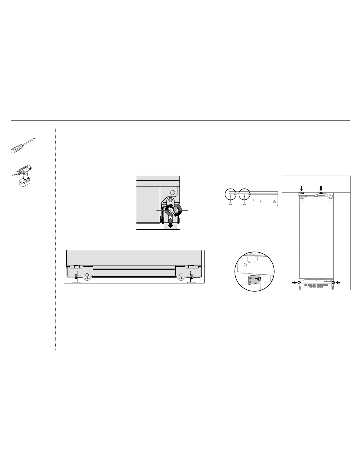
26
5 Fix each top bracket to the ceiling surface with two 8Gx16 countersunk
screws (B).
– 457mm column = 1 bracket
– 610mm column = 2 brackets
– 762mm column = 2 brackets
Note: Make sure the product does not move as you open the door
when you install the screws.
6 Fix the alcove side brackets (1x per each side) to the alcove side
surface with 8Gx16 countersunk screws (C).
B B
C C
B
IMPORTANT!
Make sure to remove the depth alignment brackets before fixing
the product inside the cabinetry.
Open the product door to remove the alignment brackets from
both sides of the product, and then re-tighten the screws.
2 Continue turning the adjusting screws alternately between front and rear
feet until you achieve the correct alignment.
3 Once you are satisfied with the alignment, raise the height of the product
by alternately adjusting the front and rear feet until the top surface contacts
the alcove ceiling.
– Check the alignment gauges while adjusting the screws to make sure
you maintain the alignment of the product.
4 Ensure all feet are positively engaged with the floor.
Rear footFront foot
IMPORTANT!
Ensure the doors are in line with the cabinetry front and the product is centred.
All four corners of the product must be supported firmly onto the floor to
eliminate any movement. Installing the product on a soft, uneven, or not level
floor may cause twisting and poor door sealing.
Tools
Cross-head screwdriver
Powered driver (optional)
A
Front foot
adjustment
Rear foot
adjustment
Adjusting height of the product inside the cabinetry
1 Turn the front and rear adjustment
screws using a cross-head
screwdriver (or powered driver)
to extend the feet until it engages
the floor.
– One turn of height adjusting
nuts is equivalent to 0.5mm
of height adjustment.
Clockwise turn raises the
height and counter-clockwise
turn lowers height (A).
– Align bottom gauge.
– Adjust height.
– Align top gauge.
Fixing the product inside the cabinetry
C
!7 SINGLE INSTALLATION
Page 29
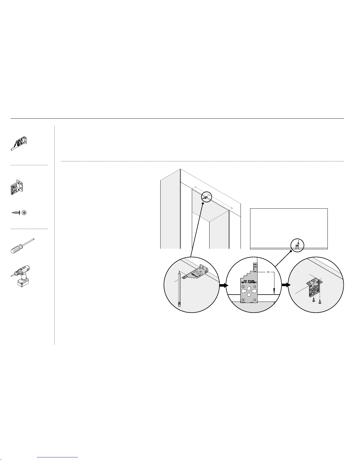
27
Attaching the central spacer to cabinetry
Note: The spacer must be attached between
the first and second products. The attachment
location of the spacer to the alcove ceiling
depends on the model of eachproduct.
1 Measure from the alcove side towards
thecentre.
Note: The alcove width for each side depends
on the size of the product to be installed.
Forexample,
– left side alcove width (A) = 457mm model
– right side alcove width (B) = 762mm model
Refer to ‘Cavity dimensions’ section for dual
install options.
2 Using one depth alignment gauge, mark the
location and depth position of the central spacer
on the alcove ceiling depending on the door
panel thickness (C).
– Make sure to follow the marked depth of
the alignment gauge relative to the door
panel (D).
3 Fix the central spacer to the alcove ceiling
with two 8Gx16 countersunk screws.
Tightenthescrews with a screwdriver or
Powered driver)(E).
IMPORTANT!
Dual installation applies to two products to be installed side by side.
A joiner kit is required and located in the Freezer model only.
The joiner kit is also available for purchase through an authorised
Fisher & Paykel dealer. Visit fisherpaykel.com for more information.
Refer to ‘Cavity dimensions’ section for cabinetry overall width for dual
install, and ‘Dual installation option’ for selecting applicable options.
We recommend to place the product (Freezer) with water connection
first into the cabinetry to allow you to check the connection before
placing the second product.
Follow the steps carefully for the correct installation of first and second
products inside the cabinetry.
A
B
E
D
C
Install fasteners kit
Cabinet depth alignment
gauge (1)
Top joiner
bracket kit
Central spacer
(1)
8Gx16 Mush washer screw
(2)
Tools
Cross-head screwdriver
Powered driver (optional)
!8 DUAL INSTALLATION
Page 30
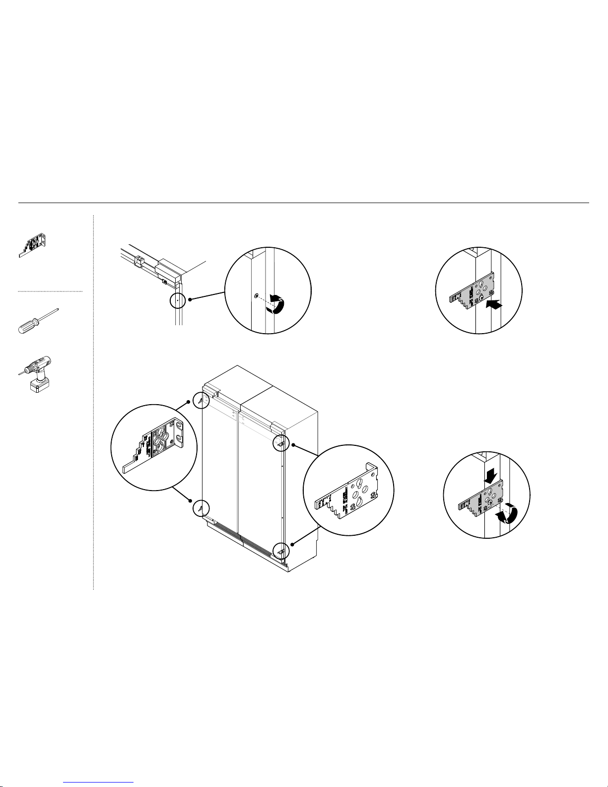
28
!8 DUAL INSTALLATION
Installing depth alignment gauges
Note: The alignment gauges are only temporary and removable after installation.
1 Loosen the screws at the right and left, top and bottom
corners of the door (A).
3 Attach the alignment gauges so that the screw
head passes through the keyhole (C).
4 Lock the position of the alignment brackets in
the keyhole, and tighten the screws just enough
to firmly hold the gauges (D).
A
2 Locate the alignment gauge
to the screws with the correct
orientation (B).
C
D
B
B
Install fasteners kit
Cabinet depth
alignment gauge
(4)
Tools
Cross-head screwdriver
Powered driver (optional)
Page 31
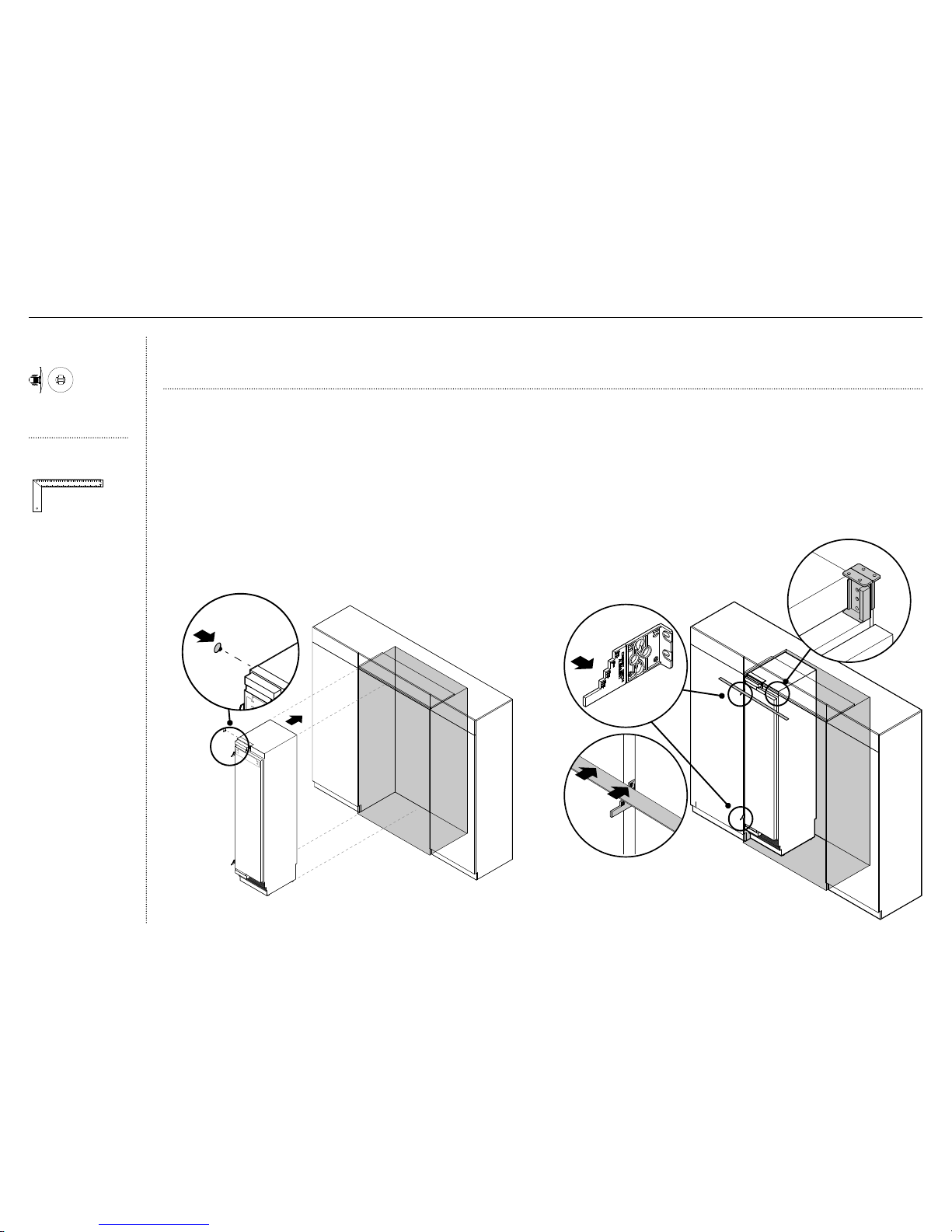
29
6 Align the top cap of the first product flush with the front of the spacer (C).
7 Mark the step (D) of each alignment gauge based on the thickness of the
door panel to be installed to the door.
8 Align the marked steps of the gauges flush with the front surface of
thecabinetry.
– Place a ruler on the steps of the alignment gauges to check if they
arein line (E) relative to the thickness of the door panel.
9 Check if the gaps between product and cabinetry side wall are even.
Positioning and aligning the first product inside the cabinetry
1 Coil the water hose flat behind the first product. (Refer to ‘Connect to
water and power supply’).
2 Before rolling the first product, insert a barbed plug into a large hole on
the cabinetry side of the product to protect the inside of the cabinetry
from being damaged by screws on the side of the product (A).
3 Roll the first product (preferably, Freezer) inside the cabinetry (B).
– Ensure that the water hose is not run over to prevent damage and
possible water leak.
4 Continue rolling the product into the cabinetry until the anti-tip bracket
overlaps [minimum 180mm the back top surface of the product.
(Refer to ‘‘Cavity Preparation’).
5 Check the clearance between the floor and the feet. Ensure the rollers
of the product can roll freely on the floor.
IMPORTANT!
Make sure that all feet engage the floor and evenly support the product.
Tighten the adjustment screw with screwdriver (do not use powered driver).
Note: The product can be rolled first into the left side or right side
of the cabinetry depending on your preference.
B
A
Install fasteners kit
Barbed plug
(2)
Tools
Ruler
E
D
C
!8 DUAL INSTALLATION
Page 32
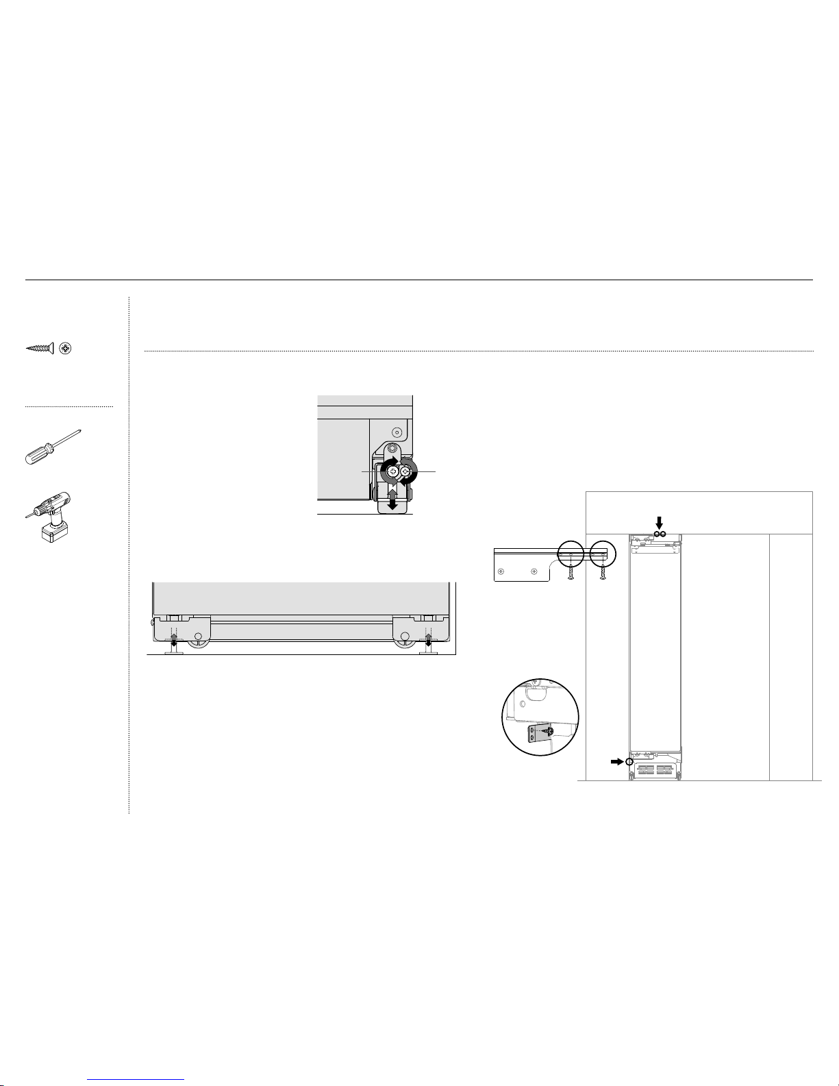
30
IMPORTANT!
Ensure the doors are in line with the cabinetry front and the product is centred.
All four corners of the product must be supported firmly onto the floor to eliminate any movement.
Installing the product on a soft, uneven, or not level floor may cause twisting and poor door sealing.
Fixing the first product inside the cabinetry
5 Fix each top bracket of first product to ceiling surface with two (2x) 8Gx16
countersunk screws (B).
– 457mm column = 1 bracket
– 610mm column = 2 brackets
– 762mm column = 2 brackets
Note: Ensure the product does not move as you open the door when you
install the screws.
6 Fix the alcove side bracket to alcove side surface with one 8Gx16
countersunk screw (C).
Note: Image shows 457mm (first product) with 1 top bracket.
B
C
Alcove side bracket
C
B
2 Continue turning the adjusting screws alternately between front
and rear feet until you achieve the correct alignment.
3 Once you are satisfied with the alignment, raise the height of the
product by alternately adjusting the front and rear feet until the
top surface contacts the alcove ceiling.
– Check the alignment gauges while adjusting the screws to
make sure you maintain the alignment of the product.
4 Ensure all feet are positively engaged with the floor.
Rear footFront foot
A
Front foot
adjustment
Rear foot
adjustment
1 Turn the front and rear adjustment
screws using a cross-head
screwdriver (or powered driver)
to extend the feet until it engages
the floor.
– One turn of height adjusting
nuts is equivalent to 0.5mm
of height adjustment.
Turnclockwise to raise the
height and counter-clockwise
to lower height (A).
Adjusting height of the product inside the cabinetry
Install fasteners kit
8Gx16 Countersunk screw
(5)
Tools
Cross-head screwdriver
Powered driver (optional)
!8 DUAL INSTALLATION
Page 33
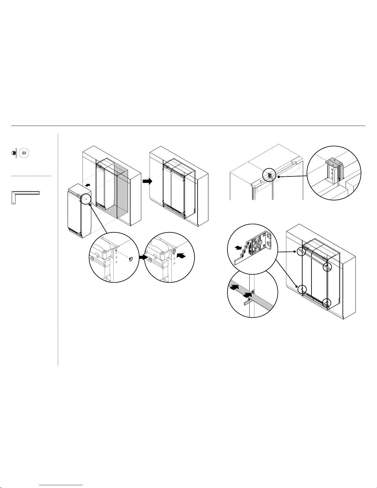
31
1 Before rolling the second product, insert a barbed plug into a large
hole on the cabinetry side of the product to protect the inside of the
cabinetry from being damaged by screws on the side of the product (B).
2 Roll the second product into the cabinetry side by side with the first
product. (A)
3 Continue rolling the product into the cabinetry until the anti-tip bracket
overlaps (min 180mm) the back top surface of the product. Refer to
‘Cavity Preparation’.
4 Check the clearance between the floor and the feet. Ensure the rollers of
the product can roll freely on the floor.
Positioning and aligning the second product inside the cabinetry
5 Align the top cap of the second product flush with the central spacer
and top cap of first product (C).
C
6 Mark the step (D) of each alignment gauge based on the thickness of
the door panel to be installed to the door.
7 Align the marked steps of the gauges flush with the edges of the
cabinetry side walls.
– Place a ruler on the steps of the alignment gauges to check if they
are in line (E) relative to the thickness of the door panel.
8 Check if the gaps between product and cabinetry side wall are even.
E
D
A
B
Install fasteners kit
Barbed plug
(2)
Tools
Ruler
!8 DUAL INSTALLATION
Page 34
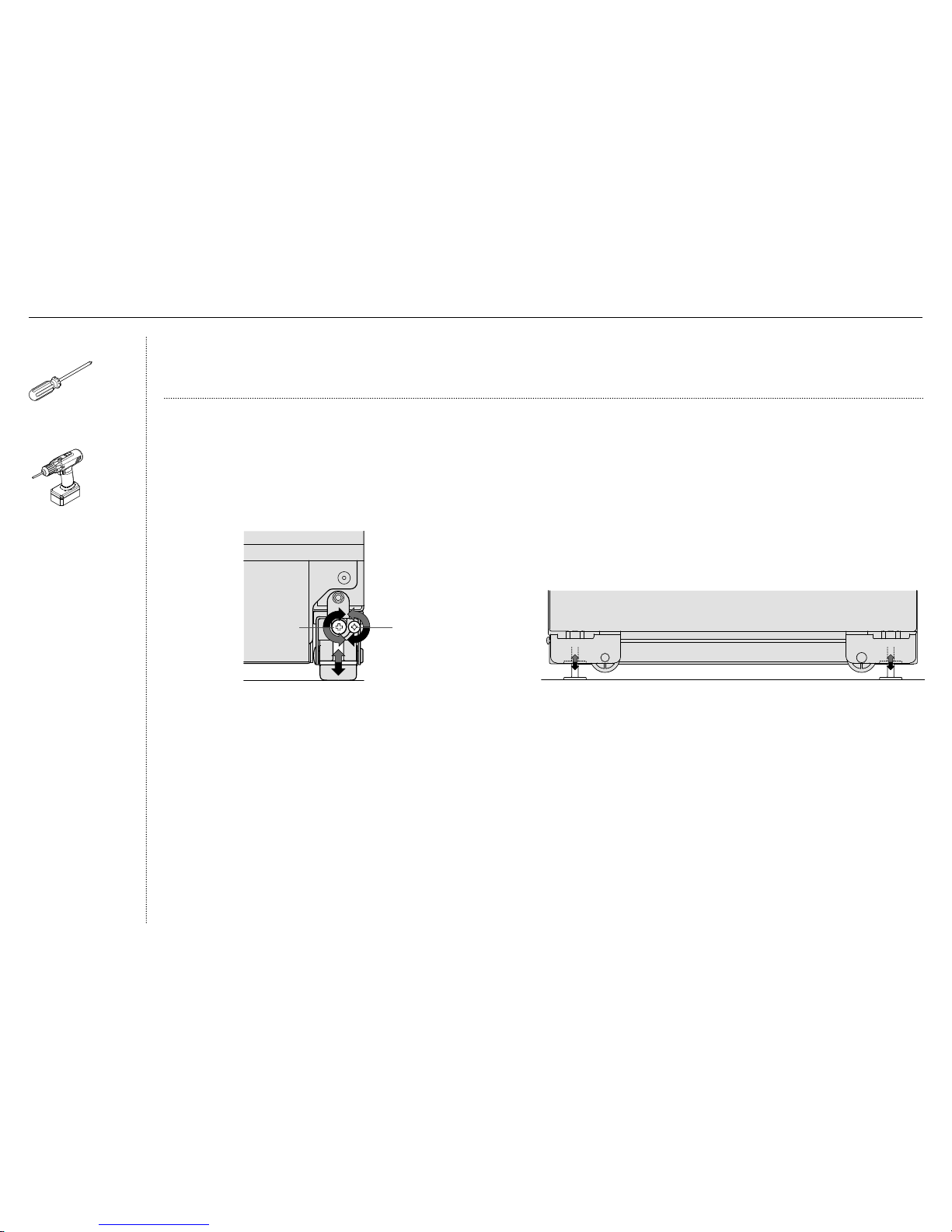
32
Rear footFront foot
Adjusting height of the second product inside the cabinetry
1 Turn the front and rear adjustment screws using a cross-head screwdriver
(or powered driver) to extend the feet until it engages the floor.
– One turn of height adjusting nuts is equivalent to 0.5mm of height
adjustment. Clockwise turn raises the height and counter-clockwise
turn lowers height (A).
2 Continue turning the adjusting screws alternately between front and rear
feet until you achieve the correct alignment of the second product with the
first product.
3 Once you are satisfied with the alignment, raise the height of the product
by alternately adjusting the front and rear feet until the top surface contacts
the alcove ceiling.
– Check the alignment gauges while adjusting the screws to make sure
you maintain the alignment of both products.
4 Ensure all feet are positively engaged with the floor.
IMPORTANT!
Ensure the door is in line with the cabinetry front and the product is centred.
All four corners of the product must be supported firmly onto the floor to eliminate any movement.
Installing the product on a soft, uneven, or not level floor may cause twisting and poor door sealing.
A
Front foot
adjustment
Rear foot
adjustment
Tools
Cross-head screwdriver
Powered driver (optional)
!8 DUAL INSTALLATION
Page 35
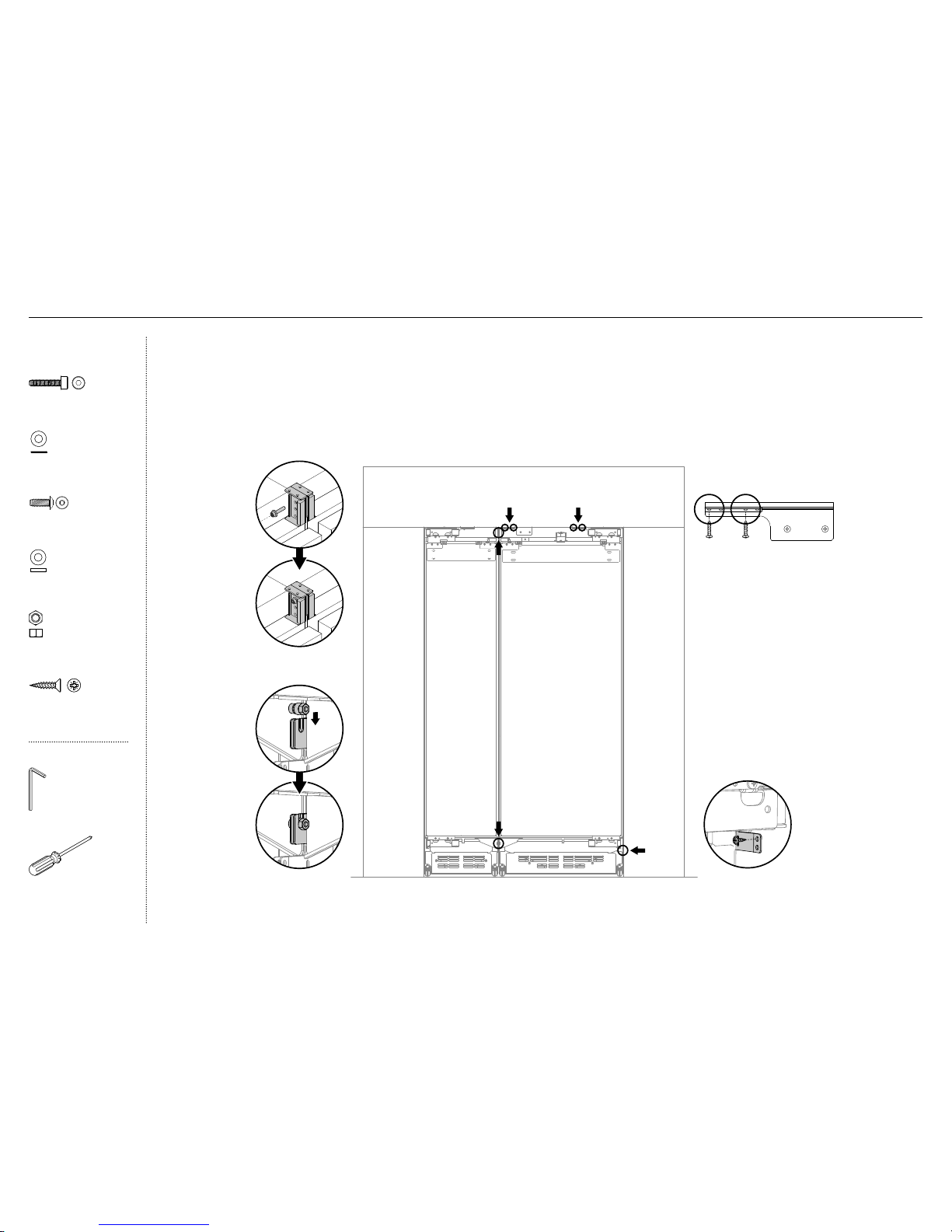
33
Fixing the second product inside the cabinetry
1 Fix the top caps of first and second products to the central spacer with the
top joiner fastener kit (A).
2 Fix the bottom joiner brackets of both products together with the bottom
joiner kit (B).
– Place the plastic washers between the bottom joiner brackets before
fixing with the screw and nut. Tighten with M4 hex key.
3 Fix the top brackets (C) and bottom alcove side bracket (D) of the second
product to the cabinetry with 8Gx16 countersunk screws.
4 Do final alignment check. Ensure the feet of both products are positively
engaged with the floor.
A
C
B
D
C
Note: Image shows 762mm (second product) with 2 top brackets.
Alcove side bracket
D
C
Bottom joiner brackets
B
Top joiner brackets
with central spacer
A
Dual install
joiner kit
M5x20 Cap
screw (1)
M5x16x1 Plain washer
(1)
M6 Washer
843453
M5 Washer
M5 x20
Cap Screw
847984
M6 x 12
Cap Screw
248072
8Gx16
Mush Washer
840371
10 x 50
Dual Lock
M6 Nut
839455
M5 Nut
839107
M6x16 Washer screw
(1)
M6x12x3.2 Plastic washer
(1)
M6 Hex nut
(1)
8Gx16 Countersunk screw
(5)
Tools
M4 Hex key
Cross-head screwdriver
!8 DUAL INSTALLATION
Page 36
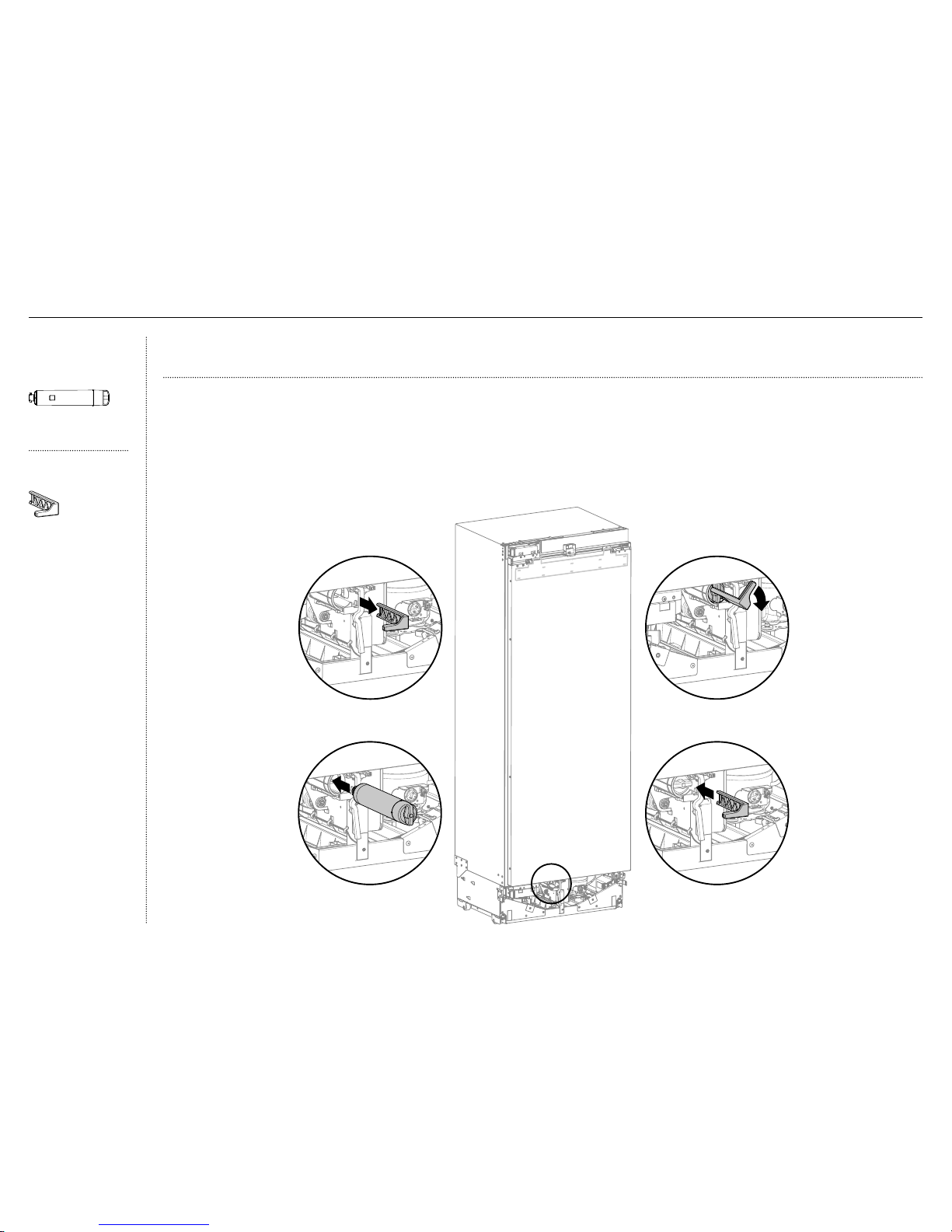
34
Water filter
install kit
Water filter
(1)
Tools
Filter cartridge tool
(1)
Install the water filter
1 Remove the water filter packaging.
2 Pull the filter tool gently to dislodge from the front of the product (A).
3 Insert the water filter all the way into the filter casing and press firmly
until the filter head is pushed further inside the casing (B).
4 Using the filter tool, rotate the filter head 90° to lock in place (C).
5 Return the filter tool to its storage position (D).
6 Turn on the water supply to check for leaks.
A
B
C
D
IMPORTANT!
The water filter head must be firmly pushed into the product and secured. incorrect installation can lead to water leaks.
!9 WATER FILTER INSTALLATION
Flushing the water filter
Before turning on your automatic ice maker, the water filter must
be flushed to remove any impurities or trapped air in the water
tank and filter system.
Refer to the user guide ‘Operating steps— Automatic ice maker
(freezer only)’.
Page 37
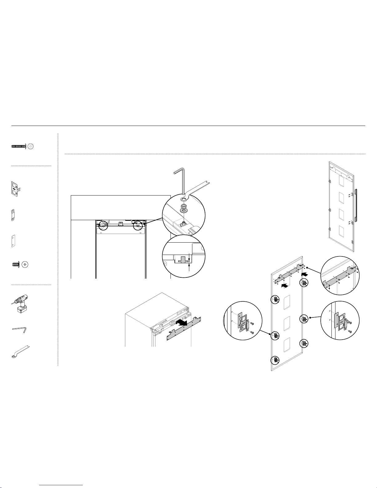
35
IMPORTANT!
Ensure to protect the finish of the Fisher & Paykel Stainless Steel door panels.
Leave the protective film on the panels when hanging and remove the film only when the installation is complete.
E
D
F
B
2 Remove the hanging bracket
from the top of the door
and set aside (B).
3 Unscrew the adjustment
screws by 3mm to move
close to the middle of
adjustment range (C).
Remove hanging bracket
1 Remove the M8 washer and M8 nut from
the M8 screws at the top the door (A)
using the supplied hex key and spanner.
Attach the door handle
4 Remove the plastic plugs from handle
holes(x4).
5 Align the handle to the holes and secure
withM5x25 hex screws (D).
Attach the hanging and side brackets
6 Align the screw holes of the hanging bracket
with the screw holes of the door panel, and
fix with 8Gx16 mush washer screws (E).
– 6x screws for 457mm
– 10x screws for 610mm and 762mm
7 Align the side panel bracket assembly
(bracket, slider and spacer) to the screw
holes on the side of the door panel and fix
with 8Gx16 mush washer screws (F).
D
Door handle kit
M5x25 Hex screw
(4x)
Door panel
attachment kit
Side bracket
(6)
Bracket slider
(6)
Bracket spacer
(6)
8Gx16 Mush washer screw
(30)
Tools
Powered driver
(with 2.5mm drill bit)
M4 hex key
(1)
13mm spanner (1)
@0 DOOR PANEL INSTALLATION (STAINLESS STEEL)
A
3mm
C
Page 38
36
Tools
Cross-head screwdriver
Powered driver
(with 2.5mm drill bit)
M4 hex key
(1)
13mm spanner
(1)
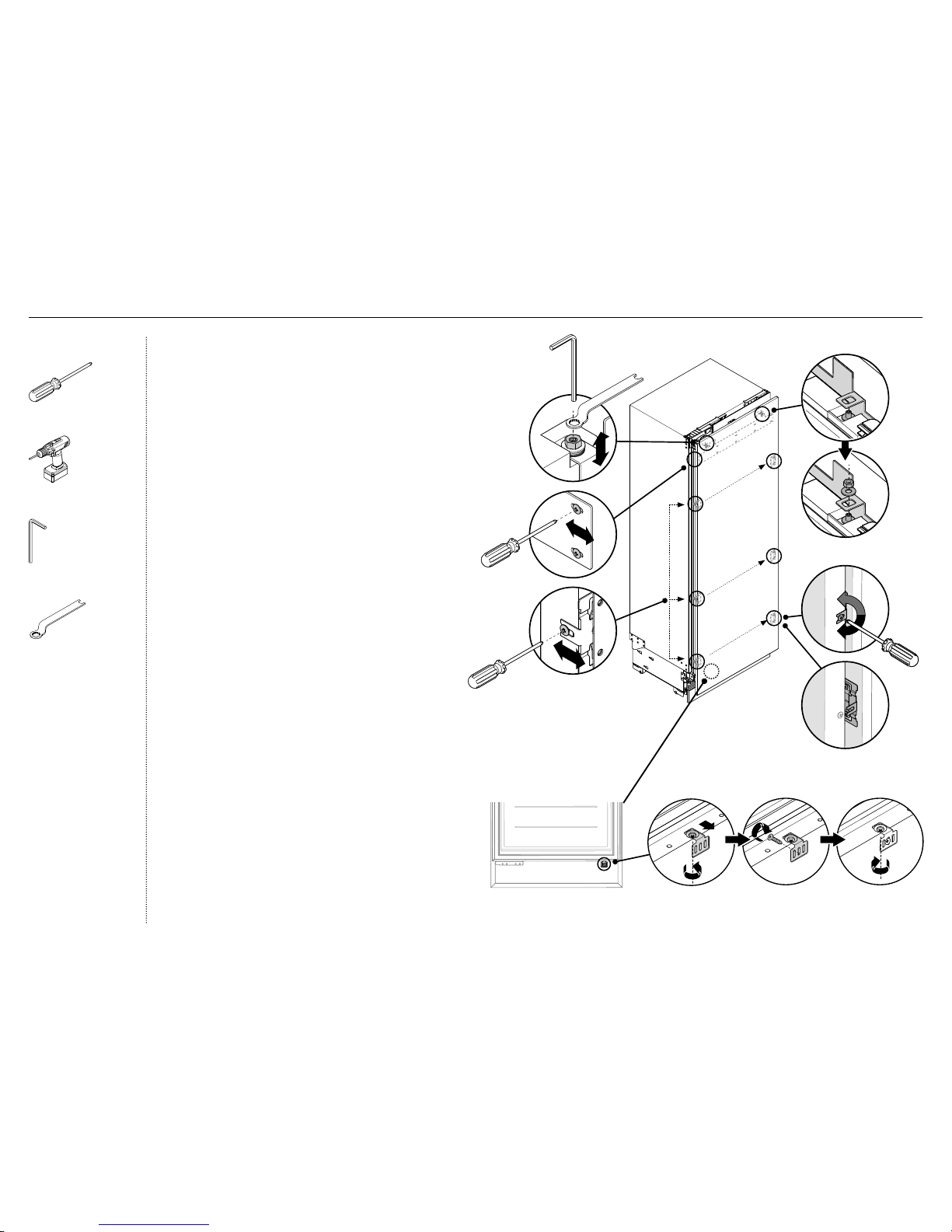
Hang the door panel
1 Remove the gauges and retighten the screws. Open the
door and loosen the screws at both sides of the door
(donot remove) (A).
2 Hang the door panel with a small angle to the door by
locating the holes of the top bracket to the M8 studs (B),
and rotate the door panel down so that the side attachment
brackets slide onto the side screws of the door. (C)
3 Screw the M8 washer and nut to the stud (D), and
re-tighten the side screws (A) to fix the door panel (donot
fully tighten). This will allow opening the door without
affecting adjustment of the door panel.
Note:
We recommended to load the shelves in the product door
with weights to ensure an accurate door panel gap width.
Weight recommendations:
– 457mm product: 10kg
– 610mm product: 15kg
– 762mm product: 20kg
Adjust the door panel
Note: Check the gaps between door panel/cabinetry using
the gauge (3mm). All door panels have full axis adjustment
to ensure they are flush with adjacent walls.
1 To adjust the height of the door panel relative to the door,
use M4 hex key to turn the top M8 screw (E) clockwise to
lower or counter-clockwise to raise the door panel until the
gap with the cabinetry above is 3mm.
2 To adjust the depth of the door panel, loosen the side
screws (F) from each side and slide the panel forward/
backward. Re-tighten once satisfied.
3 To adjust the door panels further, remove the door panels
then loosen the fixing screws for the hanging bracket and
move the bracket sideways to suit. (G)
4 Once satisfied with the door panel position, fully tighten M8
washer and nut to the stud using the supplied hex key and
spanner (E).
Fix the locking brackets
1 Loosen the screw at the bottom of the door, and slide the
locking bracket out until it touches the panel (H).
2 Fix the locking bracket to the door panel with 8Gx16
countersunk screw (I).
3 Re-tighten the screw at the bottom of door (J).
C
A
D
B
G
F
E
J
I
H
@0 DOOR PANEL INSTALLATION (STAINLESS STEEL)
Page 39
37
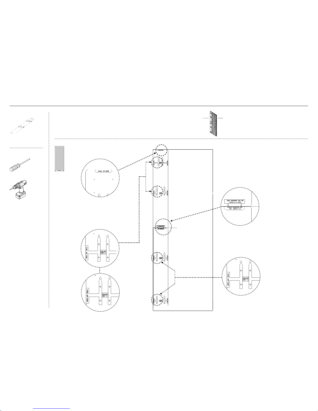
2 Align left side edge of
template with left side
edge of door panel.
back side of
door panel
front side of
door panel
IMPORTANT!
Place the template on the back side of the door panel.
Follow steps 1 – 2 if attaching a left hinge door panel, and steps
3 – 4 if attaching a right hinge door panel.
External box
Door panel template
(1)
Required tools
Cross-head screwdriver
Powered driver
(with 2.5mm drill bit)
1 Align the top edge of
the template with top
edge of top door panel.
5 Flip the template over and align the
left side edge of the template with
the left side edge of door panel.
4 Mark the reference line for the
bottom 3 and 4 holes.
3 Mark drill locations of the screw
holes for the hanging bracket and
side brackets. Drill screw holes (2mm
diameter) to the marked locations.
6 Mark drill locations of the screw holes for
the side brackets. Drill screw holes (2mm
diameter) to the marked locations.
@1 DOOR PANEL INSTALLATION (CUSTOM)
Using the installation template
(for left side of door panel)
Page 40
38
back side of
door panel
front side of
door panel
IMPORTANT!
Place the template on the back side of the door panel.
Follow steps 1 – 2 if attaching a left hinge door panel, and steps
3 – 4 if attaching a right hinge door panel.
External box
Door panel template
(1)
Required tools
Cross-head screwdriver
Powered driver
(with 2mm drill bit)
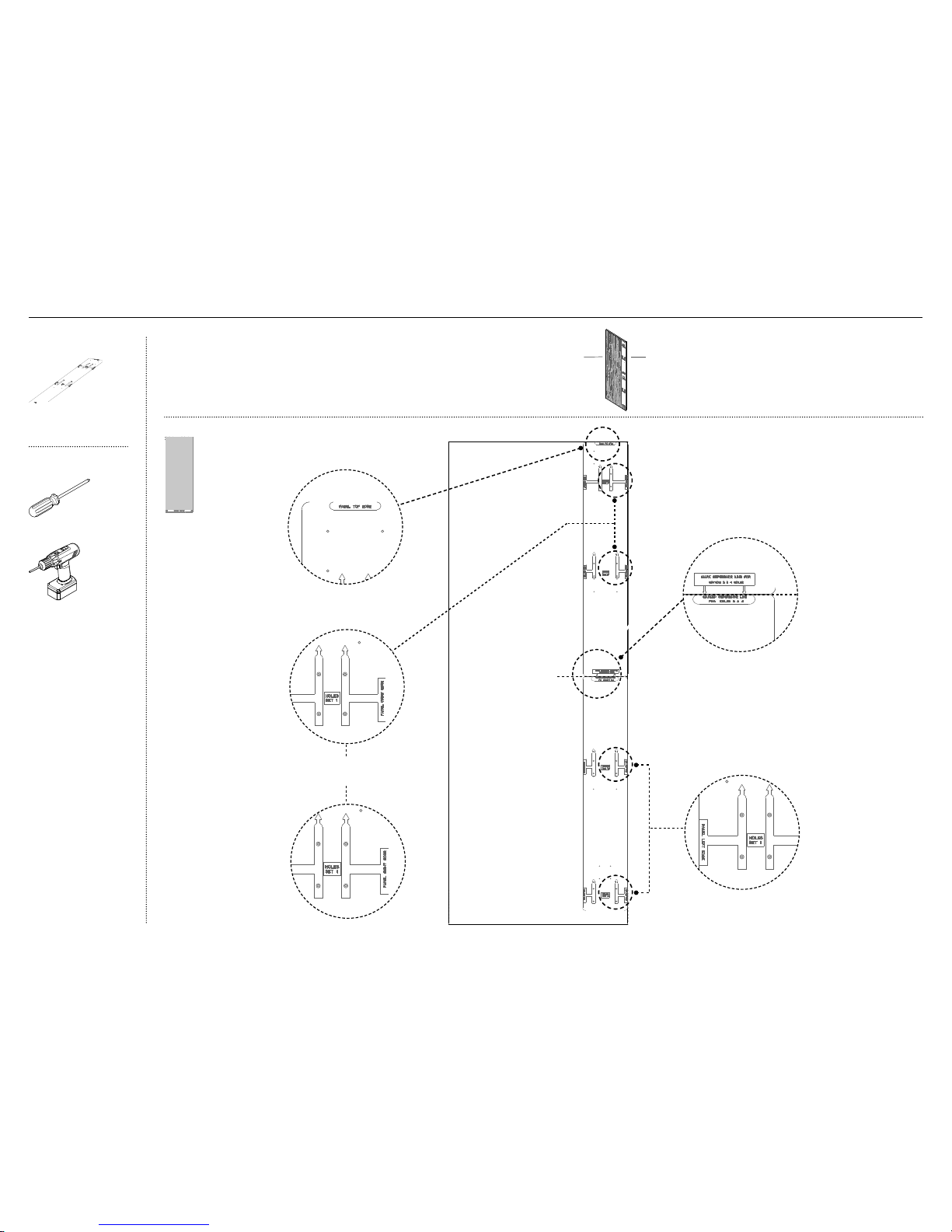
Using the installation template
(for right side of door panel)
1 Align the top of the
template with top edge
of top door panel.
4 Mark the reference
line for the bottom
3 and 4 holes.
5 Flip the template over and align
the right side edge of template
with right side edge of door panel.
2 Align right side edge of
template with right side
edge of door panel.
3 Mark drill locations of the screw
holes for the hanging bracket and
side brackets. Drill screw holes (2mm
diameter) to the marked locations.
6 Mark drill locations of the screw holes for
the side brackets. Drill screw holes (2mm
diameter) to the marked locations.
@1 DOOR PANEL INSTALLATION (CUSTOM)
Page 41
39
IMPORTANT!
Ensure the screw pilot holes do not penetrate the full depth of the panel.
Do not place the handle holes in marked areas to avoid clashing with panel attachment brackets.
Minimum panel thickness where screw hole is drilled must be 16mm.
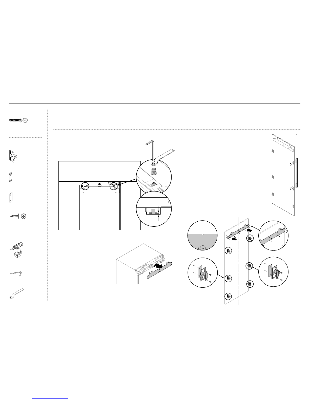
Remove hanging bracket
1 Remove the M8 washer and M8 nut fromthe
M8 screws at the top the door (A) using the
supplied hex key and spanner.
Attach the door handle
5 Fix the handle with M5x25 hex screws from the inner
edge of the panel (D). Refer to ‘Custom door panel
dimensions’ section to ensure door handle does not
interfere with side attachment brackets.
Attach the hanging and side brackets
6 Mark the centreline from the top of the Custom
panel and align with the ‘V’ notch in the bracket (E).
7 Align the screw holes of the bracket with the screw
holes of the door panel and fix the hanging bracket
to the door panel with M5x12 Cross-head screws (F).
– 6 screws for 457mm
– 10 screws for 610mm and 762mm
8 Align the side panel bracket assembly (bracket,
slider and spacer) to the screw holes on the side
of the door panel and fix with 8Gx16 mush washer
screws (G).
D
B
2 Remove the M8 washer and M8
nut fromthe M8 screws at the top
the door (B).
3 Unscrew the adjustment screws
by3mm to move close to the
middle of adjustment range (C).
4 Mark the location of the screw
holes and drill pilot holes to the
marked location.
Refer to the custom panel
template in the ‘Custom door
panel dimensions’ section.
F
G
G
E
Door handle kit
M5x25 Hex screw
(4x)
Door panel
attachment kit
Side bracket
(6)
Bracket slider
(6)
Bracket spacer
(6)
M5x12 Cross-head screw
(30)
Tools
Powered driver
(with 2.5mm drill bit)
M4 hex key
(1)
13mm spanner (1)
@1 DOOR PANEL INSTALLATION (CUSTOM)
A
3mm
C
Page 42
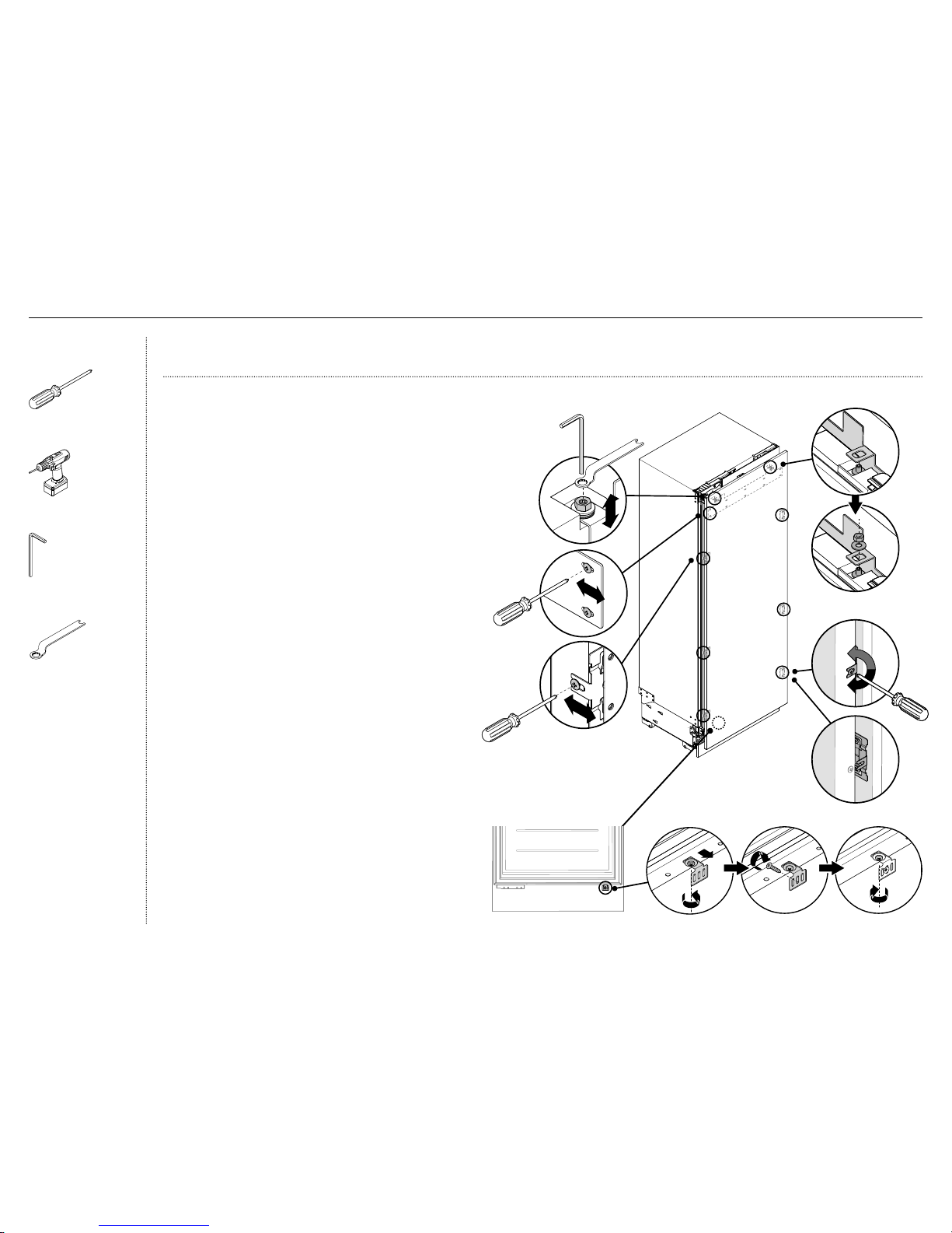
40
Tools
Cross-head screwdriver
Powered driver/drill
(with 2.5mm bit)
M4 Hex key
(1)
13mm spanner
(1)
Hang the door panel
1 Remove the gauges and retighten the screws. Open the door and
loosen the screws at both sides of the door (do not remove) (A).
2 Hang the door panel with a small angle to the door by locating
theholes of the top bracket to the M8 studs (B), and rotate the
door panel down so that the side attachment brackets slide onto
the side screws of the door. (C)
3 Screw the M8 washer and nut to the stud (D), and re-tighten the side
screws (A) to fix the door panel (do not fully tighten). This will allow
opening the door without affecting adjustment of the door panel.
Note: We recommended to load the shelves in the product door
with weights to ensure an accurate door panel gap width.
Weight recommendations:
– 457mm product: 10kg
– 610mm product: 15kg
– 762mm product: 20kg
Adjust the door panel
Note: Check the gaps between door panel/cabinetry using
the gauge (3mm). All door panels have full axis adjustment to
ensurethey are flush with adjacent walls.
1 To adjust the height of the door panel relative to the door, use
M4 hex key to turn the top M8 screw (E) clockwise to lower or
counter-clockwise to raise the door panel until the gap with the
cabinetry above is 3mm.
2 To adjust the depth of the door panel, loosen the side
screws (F) from each side and slide the panel forward/backward.
Re-tighten once satisfied.
3 To adjust the door panels further, remove the door panels then
loosen the fixing screws for the hanging bracket and move the
bracket sideways to suit. (G)
4 Once satisfied with the door panel position, fully tighten
M8washer and nut to the stud using a M4 hex key (E).
Fix the locking brackets
1 Loosen the screw at the bottom of the door, and slide the
lockingbracket out until it touches the panel (H).
2 Fix the locking bracket to the door panel with 8Gx16
countersunkscrew (I).
3 Re-tighten the screw at the bottom of door (J).
IMPORTANT!
If using Custom door panels, ensure they are prepared as per ‘Custom door panel dimensions’ section.
C
A
D
B
G
F
E
J
I
H
@1 DOOR PANEL INSTALLATION (CUSTOM)
Page 43
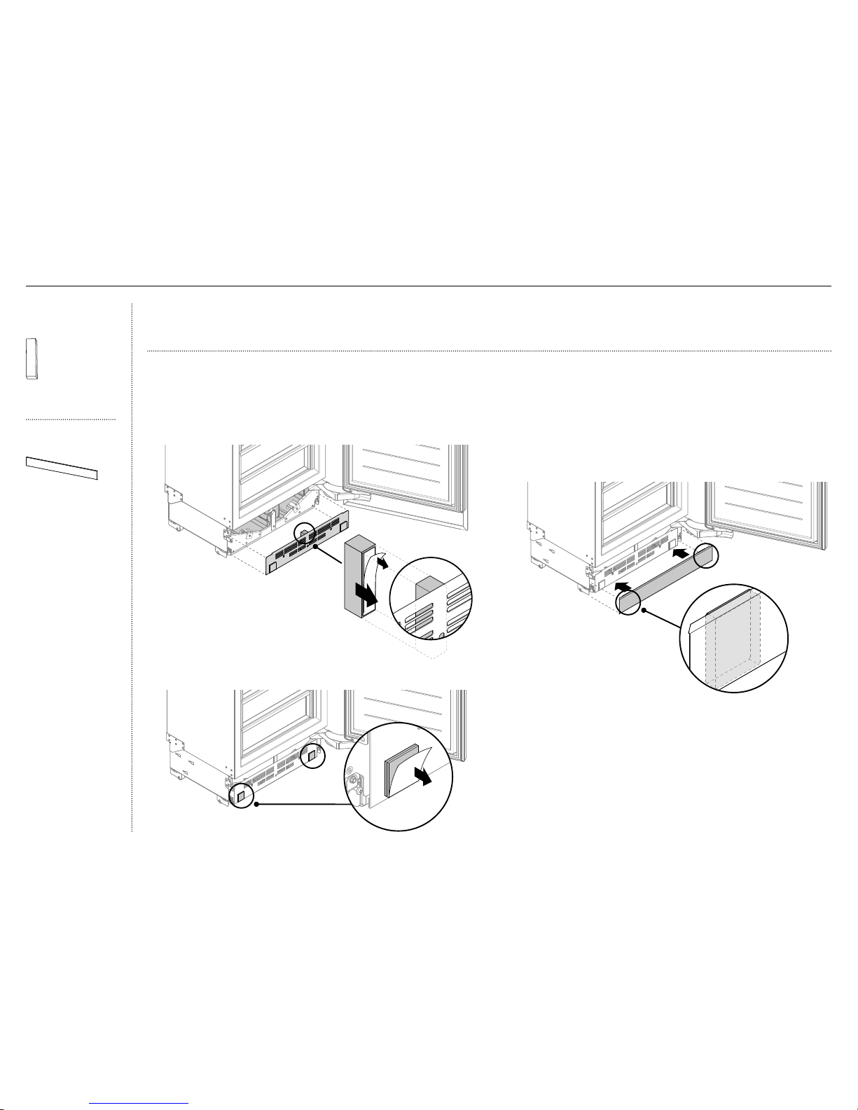
41
4 Place the toe kick in front of the mounting plate. Ensure that the spacers
at the back of the toe kick are aligned with the magnets (E).
– For custom toe kick, skip step 4 as spacers are not needed.
5 Attach the toe kick by pressing onto the mounting plate (F).
– For stainless steel: Ensure the adhesive tape of the magnets adhere
to the spacers of the toe kick.
– Ensure the bottom of the toe kick contacts the floor as you attach
to the mounting plate.
IMPORTANT!
Two magnets are pre-installed to the bottom corners of the toe kick mounting plate. Each magnet has double-sided tape to be attached to the toe kick.
This allows both Stainless steel and Custom panels to be attached to the magnet.
Install the toe kick mounting plate and toe kick
1 Reattach the toe kick mounting plate (A) to the plinth with 8x16mm
cross-head screws.
– If the toe kick depth is less than 3 5/8 in (92mm), attach an air toe kick
seal (B) to the middle of the back side of the mounting plate (C).
3 Peel off the adhesive tape backing of
the magnets located at the front bottom
corners of the toe kick mounting plate (D).
F
E
C
B
A
IMPORTANT!
For toe kick heights 114 – 127mm, shorten the lower grille by cutting
along the vertical ribs.
For 51mm toe kick height, an additional lower grille can be ordered.
For toe kick heights greater than 127mm, lower grille is not required.
Refer to ‘Door and toe kick panel dimensions’ for more information.
Miscellaneous
components
Air toe kick seal
(1)
Toe kick install kit
Toe kick
(1)
@2 TOE KICK INSTALLATION
D
Page 44
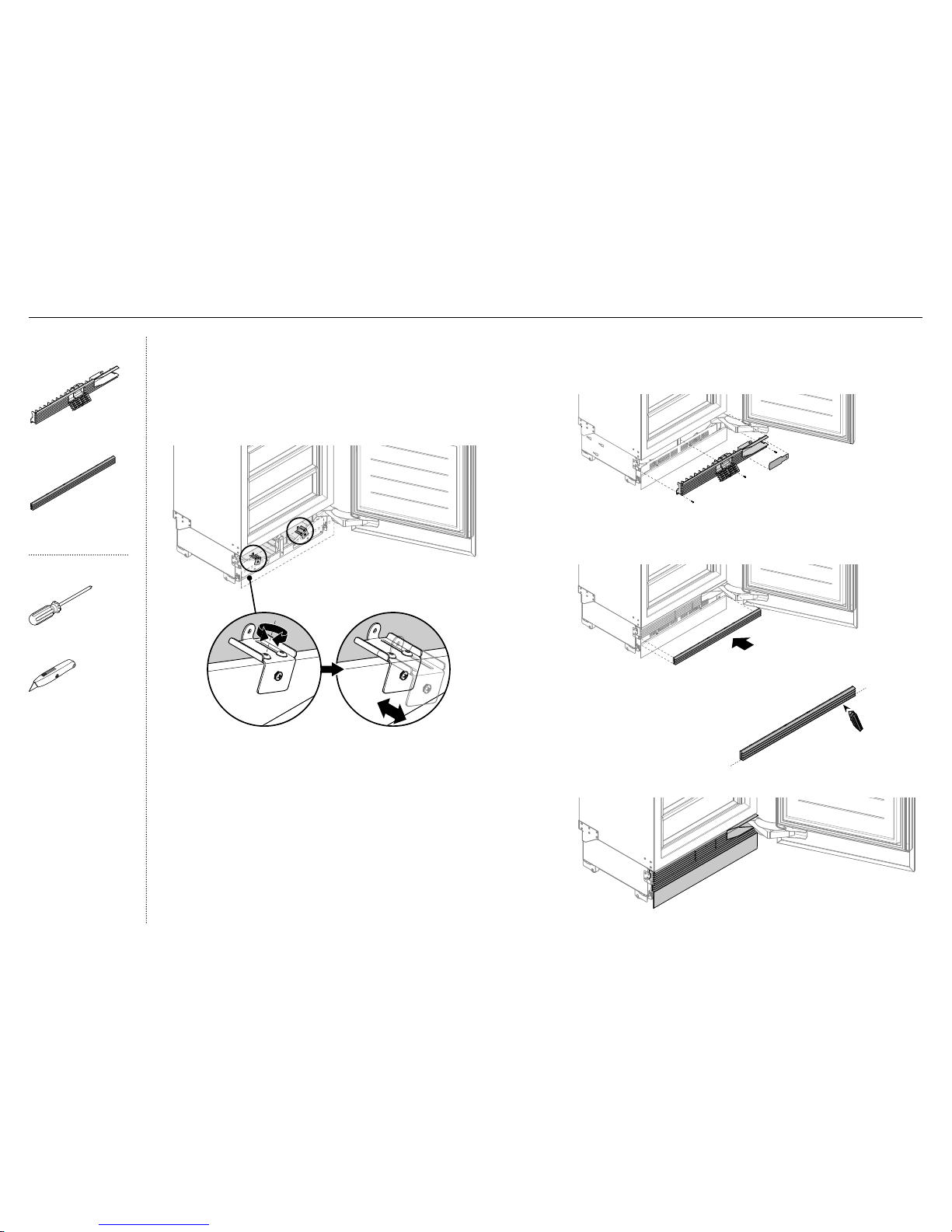
42
Toe kick and toe kick grille
complete installation
Adjusting the toe kick grille
1 Loosen the cap screws of the adjustment brackets from both
sides of the plinth using a hex key (A).
2 Adjust the toe kick to the desired depth by moving it forward/
backward (B).
3 Re-tighten the cap screws of the adjustment brackets on both
sides using the hex key.
5 Reinstall the bottom (movable) grille (E) to the mounting plate.
BA
For toe kick heights 114 – 127mm,
shorten the bottom grille by
cutting along the vertical ribs (F).
Attach the top and bottom grilles
4 Reinstall the top (fixed) grille (C) using the same screws set aside
previously, and reattach the cover (D) to the bottom hinge pocket.
C
D
E
Toe kick grilles
Top (fixed) grille
(1x)
Bottom (movable) grille
(1x)
Tools
Cross-head screwdriver
Cutter
@2 TOE KICK INSTALLATION
F
Page 45
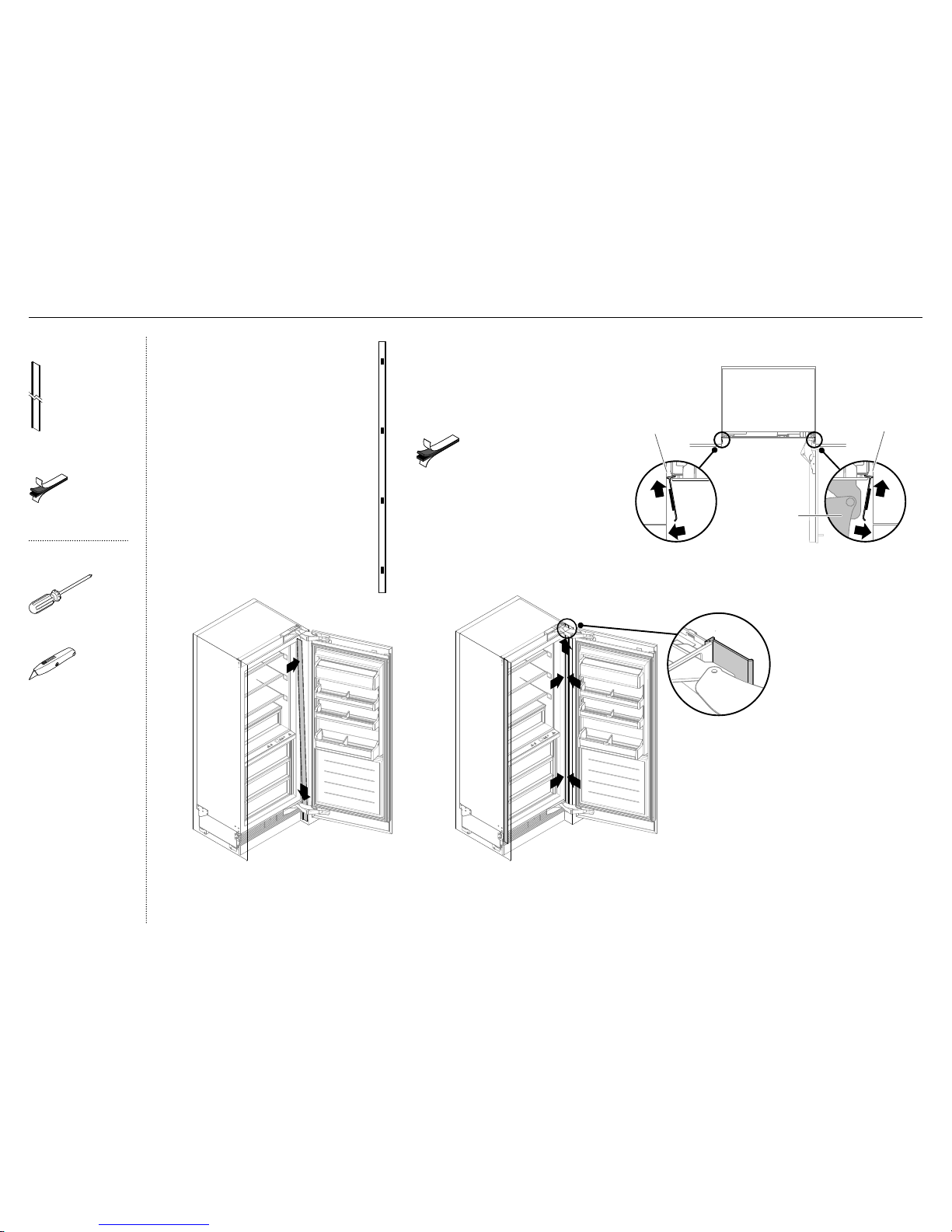
43
Install the side trims
Note: Four (4) dual-lock strips are
pre-installed along each side trim.
1 Peel off the liners from the
dual-lock strips (A).
A
3 Slide the trim behind the lower hinge (C),
then the top hinge (D). Hold the same angle
when sliding the trim.
D
C
2 Position the trim on the
throat with anangle (B).
B B
4 Slot trim in behind top hinge pocket (E),
then press (F) adhesive to cavity ensuring
trim is also tight against product inner face.
Install parts
Cabinet side trim
assembly (2)
Dual-lock strip
(4)
Tools
Cross-head screwdriver
Cutter
Note:
Press firmly on the dual-lock strip locations
toensure the side trims are securely attached.
For dual installation, do the same steps for
each product.
F
E
door hinge
trim
trim
@3 CABINET TRIMS INSTALLATION
Page 46
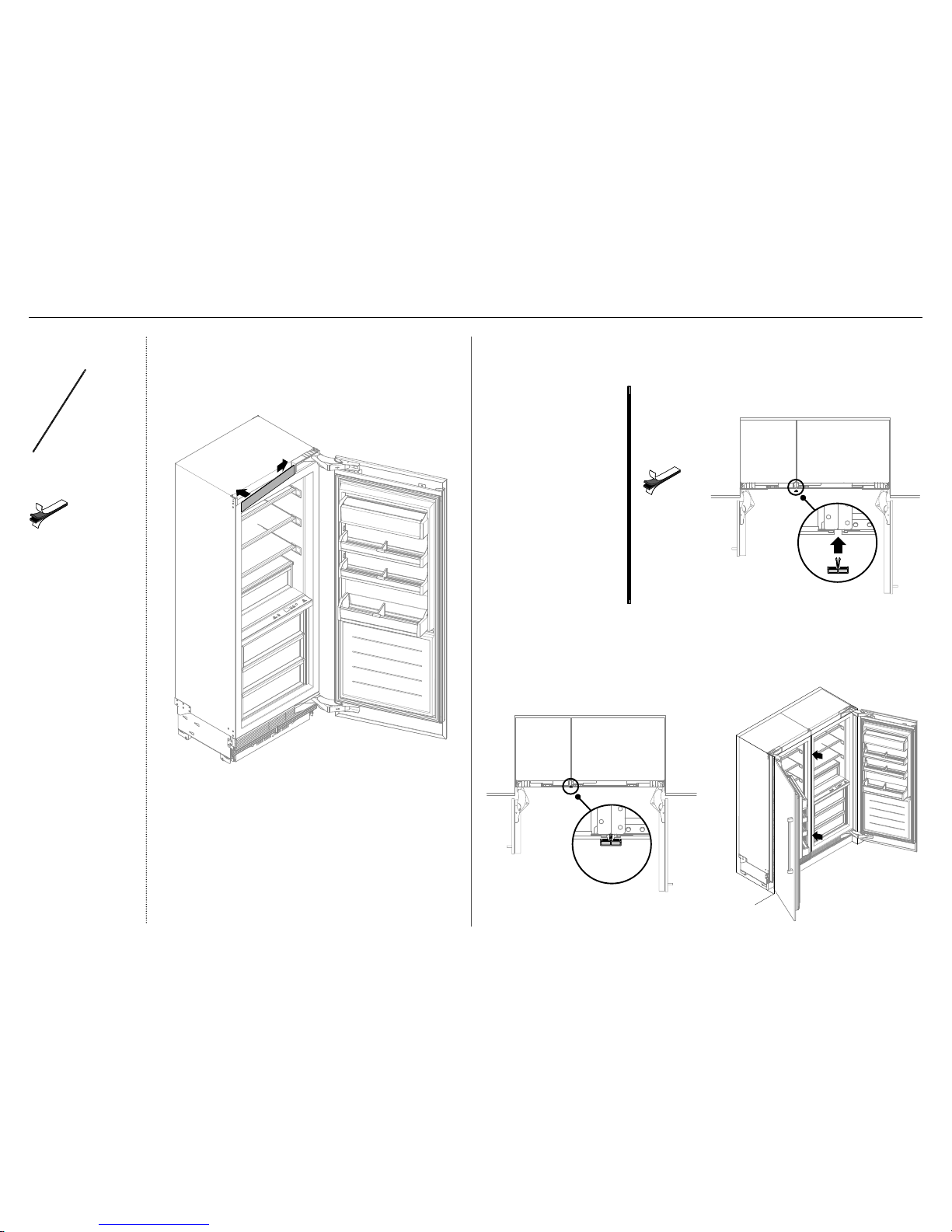
44
Reinstall the top trim
1 Slide the top trim into hinge pocket of the cabinet (A),
and then engage the dual lock at the non-hinge side (B).
B
A
Install the centre trims (for Dual install only)
Note: Four (4) dual-lock strips are pre-installed along the centre trim.
2 Position the trim between the
throats of both cabinets (D).
3 Push and press the trim on the
products/throat (E).
Note: Make sure the top end of the
trim is pushed up against the alcove
ceiling before fixing the position.
1 Peel off the liners from
the dual-lock strips (C).
4 Press the centre trim to fix
the position (F).
C
D
E
F
Dual install
joiner kit
Centre trim
(1)
Dual-lock strip
(4)
@3 CABINET TRIMS INSTALLATION
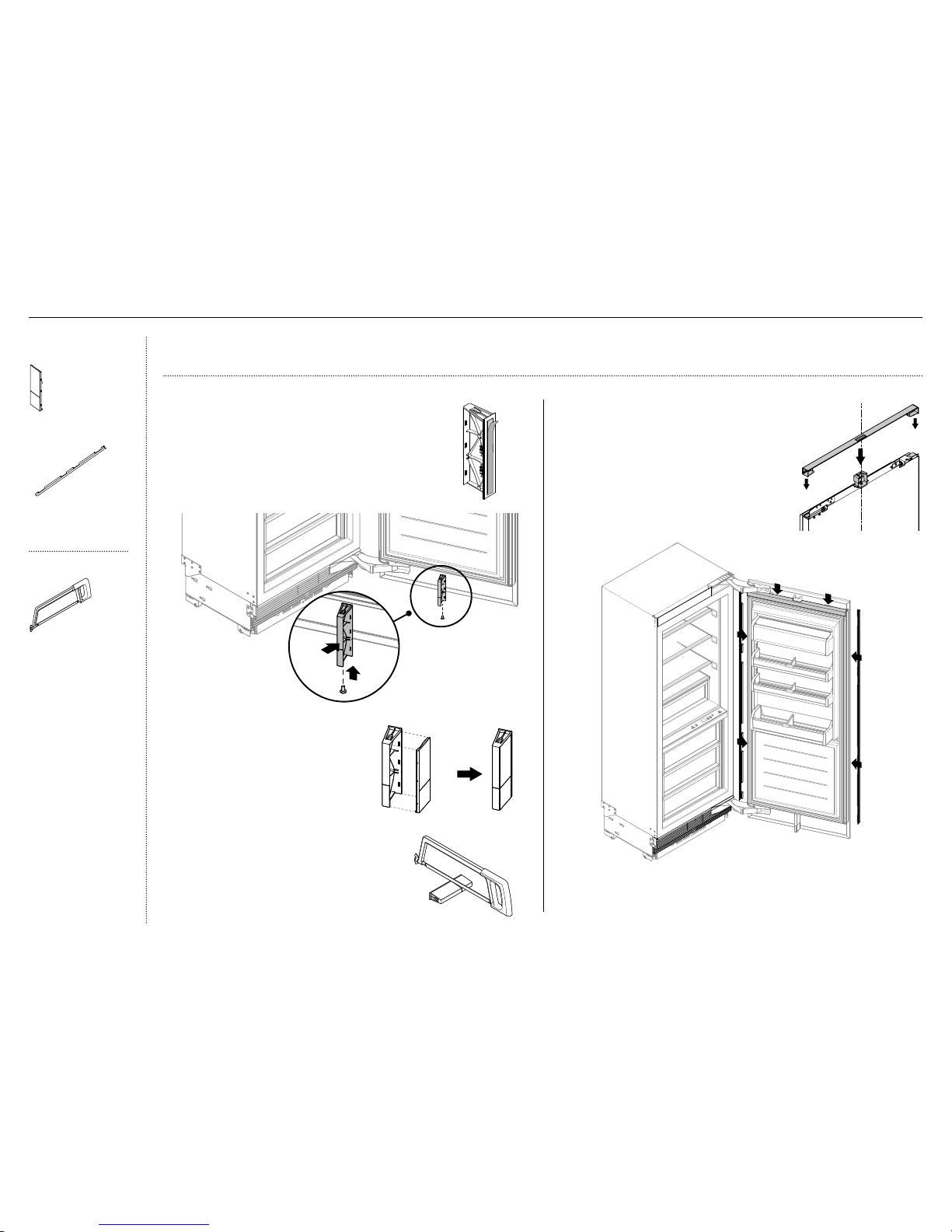
Page 47
45
IMPORTANT!
The door flow divider is pre-assembled to the door of the product. It blocks the air flow from bypassing in front of the bottom grille.
E
Note:
When fitting the air flow divider to the door
for a toe kick height greater than 102mm,
the divider requires shortening. Cutalong
the outline on both the divider and divider
cover (E) before installation to the door.
Ensure to file the cut portions of the divider
and cover.
5 Attach the flow divider cap to the
flow divider (D).
B
C
D
A
Install the door trims
1 Reinstall the door panel top extrusion to the
top of the door.
– Align the notch (F) of the extrusion with
the magnet housing at the top of door (G).
– Clip the trim caps (H) at both ends of
the extrusion to the top of the door.
– Press the top door panel extrusion down
into the top of the door (I) so that the
dual lock strips engage together.
2 Press the door panel side extrusion (J) into the gap between the door
and door panel. Align the top of the door panel side extrusion with the
top door panel extrusion. Do on each side.
J
J
J
J
I
I
H
F
G
H
Miscellaneous
components
Flow divider cap
(1)
Door panel side extrusion
(2)
Tools
Hacksaw
ReInstall the flow divider
1 Peel the adhesive layer off the flow divider (A).
2 Remove the 8Gx16 countersunk screw from the bottom
of the door and re-install the flow divider using the same
screw. (Do not tighten fully) (B).
3 Press the flow divider firmly against the door panel (C).
Make sure the adhesive layer contacts the door panel.
4 Re-tighten the screw fully.
@4 DOOR TRIMS INSTALLATION
Page 48
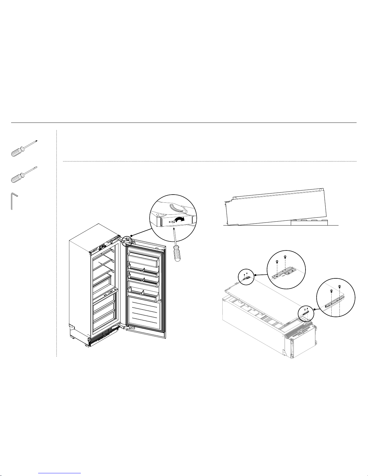
46
Removing the door
1 Release the hinge spring by turning the star T20 screws in the hinge
to the 0 position (A).
You have the option to change the door hinge side of your product from right hand hinge to left hand hinge or vice versa.
A hinge change kit is required for this installation.
IMPORTANT!
Ensure that you remove all the shelves, covers and trims from the product before changing the hinges. Take care not to damage the door.
We recommend to lay the product (door closed) onto its back on the pallet when removing the door hinges.
3 Detach the door from the product by unscrewing the door hinge
M6x10 hex screws at the top (B) and bottom (C) hinges.
2 Close the door and lay the product on its back on the pallet.
Top hinge
B
Bottom hinge
C
A
Tools
T2 star-head screwdriver
Flat-head screwdriver
Hex key
@5 OPTIONAL — CHANGING OVER DOOR HINGES
Page 49
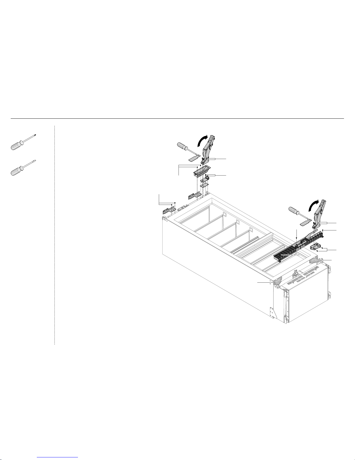
47
Removing the top door hinge
1 Rotate the top hinge (A) outwards and remove
the top hinge pocket cover (B) using the flat
head screwdriver in the slot of the cover.
2 Remove the hinge by unscrewing the M5x12
pan head screws (2x) (C), and set aside for
later use.
3 Remove the hinge pocket and top alcove
bracket by unscrewing M5x12 pan head screws
(2x) (D) from the hinge pocket.
4 Remove the top hinge bracket and spacer (E)
by unscrewing the M5x12 countersunk screws
(2x) from the top hinge bracket.
5 For the non-hinge side, remove the top alcove
bracket by unscrewing the M5x12 pan head
screws (2x) (F). (Not applicable for RS46).
Removing the bottom door hinge
6 Rotate the bottom hinge (G) outwards and
remove bottom hinge pocket cover (H) using
aflat head screwdriver in theslot.
7 Remove the hinge by unscrewing the M6x16
countersunk screws (2x) (I).
8 Open the water filter hatch on the bottom
(fixed) grille and unscrew the #8x16 screw (J)
while holding the grille in place.
9 Remove the bottom grille by unscrewing the
#8x16 screws (K) from the bottom left and
right of the grille.
!0
Remove bottom hinge bracket by unscrewing
M6x16 countersunk screws (L).
IMPORTANT!
Do not remove plinth-to-cabinet retention brackets!
A
G
E
C
D
F
J
L
B
K
I
K
H
Do not remove!
Do not
remove!
Tools
T2 star-head screwdriver
Flat-head screwdriver
@5 OPTIONAL — CHANGING OVER DOOR HINGES
Page 50
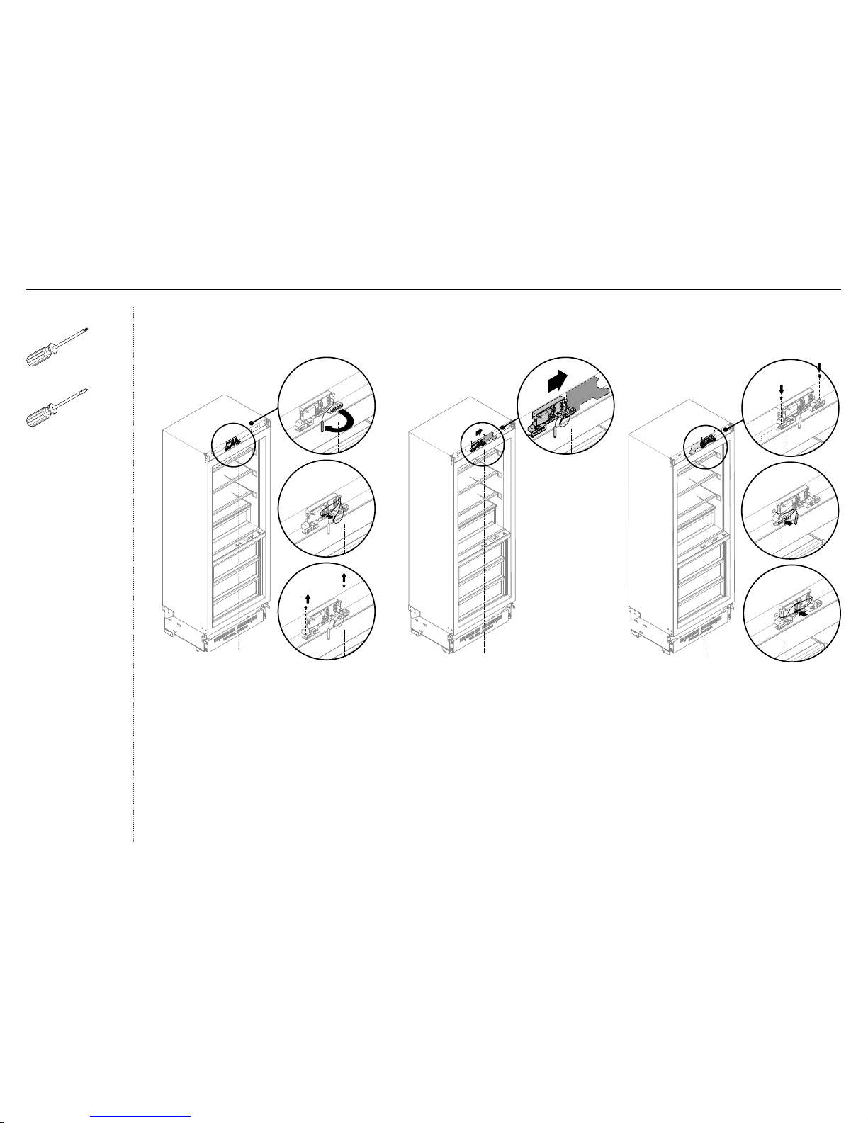
48
Moving the sensor housing
(RS46 & RS61 only)
1 Unclip the reed switch from the housing (A).
2 Unhook the interceptor board harness from
sensor housing so harness is loose (B).
3 Remove the #8x16 screws (2x) from the sensor
housing (C).
5 Reinstall the sensor housing using #8x16 screws
(2x) into the pre-drilled holes in the cabinet top
panel (E).
6 Clip the reed switch into the sensor housing in the
pocket closest to the centreline of the cabinet (F).
7 Press the harness from the interceptor board into
the forks on the sensor housing (G).
4 Move the sensor housing so that the
opposite reed switch clip is aligned with
the centre of the cabinet (D).
A
B
C
D
G
E
F
Tools
T2 star-head screwdriver
Flat-head screwdriver
@5 OPTIONAL — CHANGING OVER DOOR HINGES
Page 51
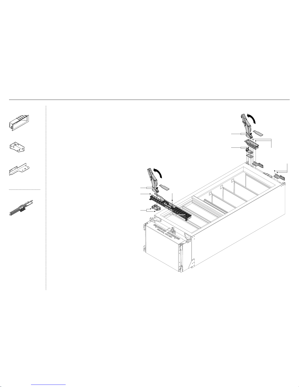
49
Top hinge installation
1 Reinstall the hinge top bracket and bracket
spacer with M5x12 countersunk screws (A)
onthe new hinge side at the other side of
theproduct.
2 Install the new hinge pocket and alcove top
bracket on the new hinge side using two (2x)
M5x12 pan head screws (B).
Note: The new hinge pocket and alcove top
bracket are supplied with the hinge kit.
3 Install the new hinge in the new hinge pocket
by screwing M5x12 pan head screws (2x) (C).
(Notapplicable to RS46).
4 Open the hinge and reinstall the top hinge
pocket cover (D) to the top hinge pocket.
5 Install a new alcove top bracket on the new
non-hinge side. (Not applicable to RS46) (E).
Bottom hinge installation
6 Install a new lower hinge bracket on the new
hinge side with M6x16 screws (2x) (F).
– Ensure that the tab on the top of the
bracket inserts into the slot in the plinth
front bracket.
7 Use the hinge that was removed from the top of
the product and insert the tabs into the hinge
lower bracket. Rotate the hinge into place and
fix with M5x12 countersunk screws (2x) (G).
8 Open the hinge (H), and install the new top
(fixed) grille assembly.
9 Fasten in place with #8x16 screws (3x) (I).
Oneeach at the bottom left and right of the
grille and one behind the water filter hatch.
!0
Reinstall the bottom hinge pocket cover to
thenew hinge pocket (J).
H
A
C
B
E
I
E
I
J
F
I
G
D
Hinge change
assembly
Hinge (right or left) top
pocket (1)
Lower (right or left) hinge
bracket (1)
K05 top (right or left)
adapter bracket (1)
Top (fixed) grille
assembly
Top (fixed) grille
(1)
@5 OPTIONAL — CHANGING OVER DOOR HINGES
Page 52
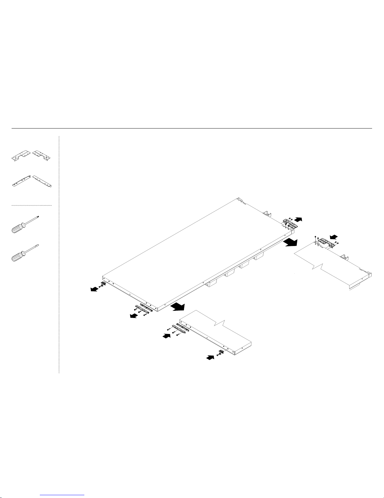
50
Door brackets
1 Remove the top adapter bracket from the top of the door
byunscrewing M5x10 screws (4x) (A).
2 Install the new top adapter bracket into the other side of
thetop of the door with M5x10 screws (4x) (B).
3 Remove the door panel locking bracket and washer from
thebottom of the door by unscrewing M6x25 screw (1x) (C).
4 Remove the bottom adapter bracket and spacer from the
bottom of the door by unscrewing M6x25 screws (2x)
andM5x30 screw (1x) (D).
5 Install the new bottom adapter bracket and existing spacer
to the other side of the door with M6x25 screws (2x) and
M5x30 screw (1x) (E).
6 Install the existing door panel locking bracket and washer
tothe other side of the door with M6x25 screw (1x) (F).
D
E
F
A
B
C
(use new bottom adaptor
bracket and spacer)
(use new top
adaptor bracket)
(use existing locking bracket)
Hinge change
assembly
K05 top adaptor
bracket R/L (1)
K05 bottom adaptor
bracket R/L (1)
Tools
T2 star-head screwdriver
Flat-head screwdriver
@5 OPTIONAL — CHANGING OVER DOOR HINGES
Page 53
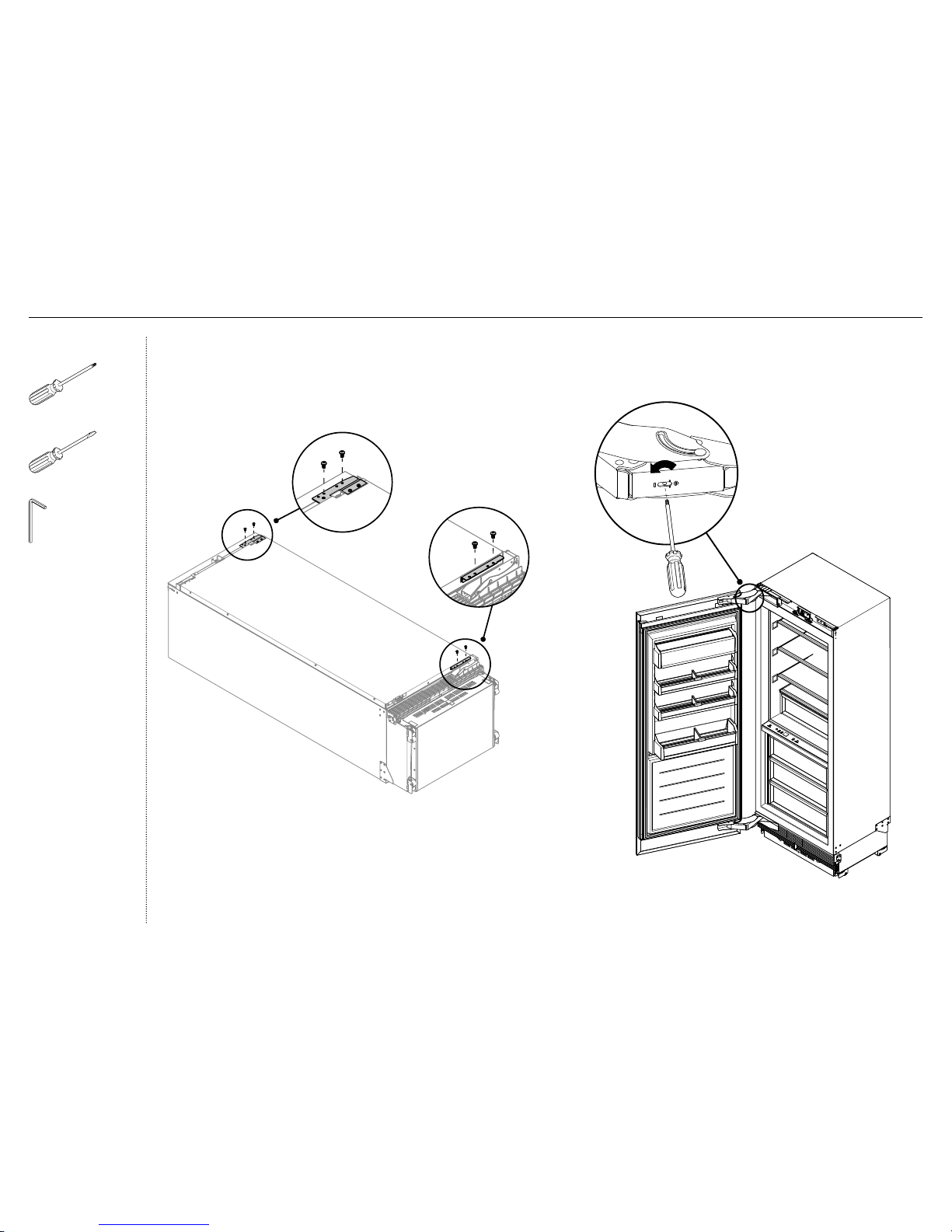
51
Top hinge
A
Bottom hinge
A
Door installation
1 Reinstall the door to the product by fixing
M6x10 hex screws (4x) into the hinges (A).
2 Activate the hinge spring by turning the
star T20 screws to the I position (B).
B
3 Return the product to the upright position.
4 Reinstall all covers and trims.
Tools
T2 star-head screwdriver
Flat-head screwdriver
Hex key
@5 OPTIONAL — CHANGING OVER DOOR HINGES
Page 54

52
TO BE COMPLETED BY THE INSTALLER
All models
Check all parts are installed.
Ensure the product is level.
Ensure the product is securely fastened to the cabinetry with the
supplied anti-tip bracket and fittings.
Ensure the door/drawer can open and close freely with no resistance
from surroundingcabinetry.
Ensure hinge limiting bolt is fitted for 90° door swing.
Ensure all internal and external packaging is removed from the
product before use.
Freezer models only
Ensure the water filtration system has been flushed.
Ensure a manual ice maker cycle has been forced.
Complete and keep for safe reference:
Model _________________________________________________________
Serial No. _________________________________________________________
Purchase Date _________________________________________________________
Purchaser _________________________________________________________
Dealer Address _________________________________________________________
Installer’s Name _________________________________________________________
Installer’s Signature _________________________________________________________
Installation Company _________________________________________________________
Installation Date _________________________________________________________
@6 FINAL CHECKLIST
Page 55

Page 56

FISHERPAYKEL.COM
NZ AU GB EU
862367A 03.19
© Fisher & Paykel Products 2019. All rights reserved.
The product specifications in this booklet apply to the specific products
and models described at the date of issue. Under our policy of continuous
product improvement, these specifications may change at any time. You
should therefore check with your Dealer to ensure this booklet correctly
describes the product currently available.
 Loading...