

Page 1

ACTIVESMART™ INTEGRATED
FRENCH DOOR/DRAWER REFRIGERATOR
RS6A72 models
INSTALLATION GUIDE
US CA
844185A 07.18
Page 2

Page 3

CONTENTS
FOLLOW THE INSTALLATION SEQUENCE RELEVANT TO YOUR CABINETRY
1 SAFETY AND WARNINGS
2 COMPONENTS LIST
3 PRODUCT AND CAVITY DIMENSIONS
4 CABINETRY OPTIONS
5 DOOR PANEL DIMENSIONS
6 CUSTOM DOOR PANEL INSTALLATION DIMENSIONS
7
DOOR OPENING ROTATION
8
ELECTRICAL AND PLUMBING
9
BEFORE INSTALLATION
!0 ATTACH ANTI-TIP BRACKET
!1 REMOVE HINGE END CAPS
!2 CONNECT TO WATER AND ELECTRICAL SUPPLY
!3 ALIGN YOUR PRODUCT INSIDE CABINETRY
!4 INSTALL WATER FILTER CARTRIDGE AND TOE KICKS
!5 ASSEMBLE DOOR PANEL SET
!6 HANG ICE & WATER DOOR PANEL
!7 HANG NON-WATER DISPENSING DOOR PANELS
!8 ATTACH TOP TRIM AND HINGE END CAPS
!9 ATTACH COVERS AND DOOR/DRAWER TRIMS
@0 ATTACH CABINET SIDE TRIMS
@1 FINAL CHECKLIST
1
Page 4

Page 5
1 SAFETY AND WARNINGS
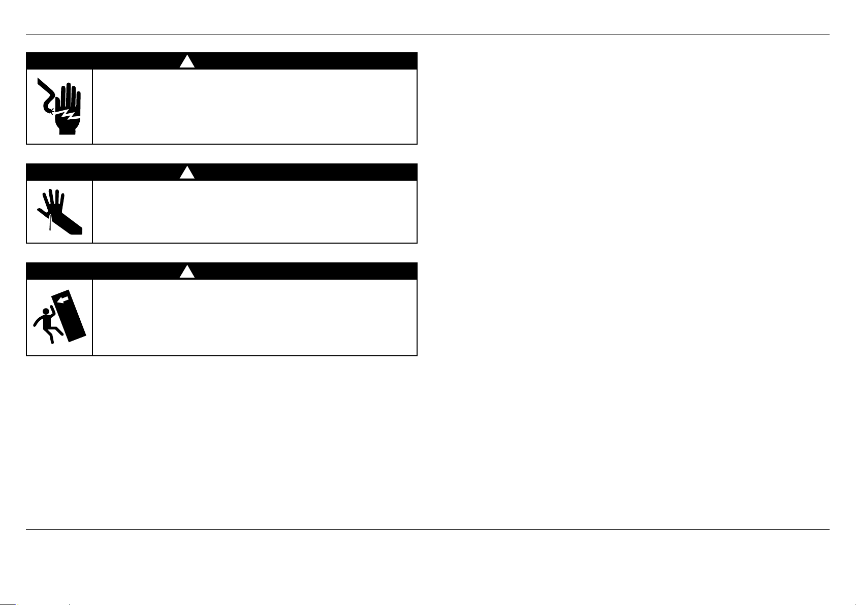
!
WARNING!
Electric Shock Hazard
Read and follow the safety and warnings outlined in this installation
guide before operating this refrigerator.
Failure to do so can result in death, electric shock, fire or injury
topersons.
!
WARNING!
Cut Hazard
Take care – panel edges are sharp. Failure to use caution could result
ininjury or cuts.
!
WARNING!
This refrigerator is top-heavy and must be secured to prevent the
possibility of tippingforward.
To ensure that the refrigerator is stable under all loading conditions,
theanti-tip bracket and fittings supplied must be installed according
tothe following installation instructions by a professional installer.
IMPORTANT!
The water connection to your Ice & water refrigerator must be installed by an
authorized plumber or Fisher & Paykel trained and supported service technician
andcomply with all state and local laws.
Installation and use MUST comply with all state and local plumbing codes.
Checkwithyour local public works department for plumbing codes. You must follow
their guidelines as you install the water filtration system.
To avoid serious illness or death, only connect your water filter to safe drinking water.
The water filter cartridge needs to be changed when the replacement indicator icon
illuminates. This will happen every 6 months.
If the water filtration system has been allowed to freeze, replace filter cartridge.
Failure to replace the disposable filter at recommended intervals may lead to reduced
filter performance and failure of the filter, causing property damage from water
leakage or flooding.
In cases of excessively reduced filter life – we recommend that you consult a local
plumber or your water supplier for advice on suitable filtration requirements for the
water supplied to your home.
Filter replacement is the consumer’s responsibility and will not be covered by the
warranty except in the case of faulty parts or materials within the filter cartridge.
If the water has not created ice for some time or ice has an unpleasant taste or
odor dispose of ice and refer to the flushing instructions detailed in the installation
sectionof this user guide/installation guide. If unpleasant taste or odor persists,
youmay wish to fit a new filter cartridge.
Use new tubing supplied with the refrigerator. DO NOT reuse old tubing from old
water and ice connections.
Your water filtration system can withstand up to 120psi (827kPa) of water pressure.
Ensure the supplied pressure reducing valve is installed before installing the water
filtration system. DO NOT install if water pressure exceeds 120psi (827kPa).
To reduce the risk associated with property damage due to water leakage or flooding:
DO NOT install systems in areas where ambient temperatures may go above 100°F
(38°C) or drop below 33°F (0.6°C).
DO NOT install on hot water supply lines. The maximum operating water temperature
of this filter system is 100°F (38°C).
DO NOT install where water hammer conditions may occur. If water hammer
conditions exist, you must install a water hammer arrester.
WARNING!
To reduce the risk associated with choking:
DO NOT allow children under 3 years of age to have access to small parts during
theinstallation of the water filter.
IMPORTANT!
SAVE THESE INSTRUCTIONS
The models shown in this installation guide may not be available in all markets and are subject to change at any time. For current details about model and specification availability in your country, go to our
website fisherpaykel.com or contact your local Fisher & Paykel dealer. Note that the word ‘refrigerator’, throughout this user guide, refers to the combination of refrigerator/freezer products.
3
Page 6
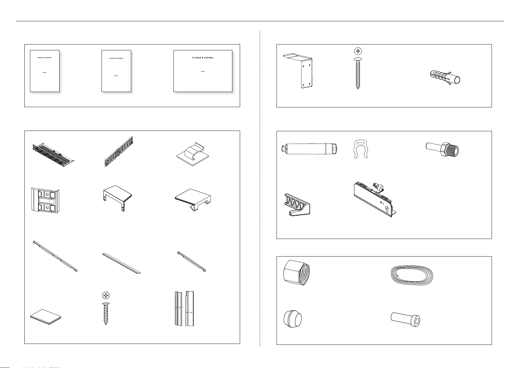
2 COMPONENTS LIST
MI (miscellaneous items) pack — included with the refrigerator
ACTIVESMART™
INTEGRATED REFRIGERATOR
RS90A, RS9120W,
RS36A72, RS36A80 & RS36W80 models
USER GUIDE
NZ AU GB IE HK SG IN US
SERVICE & WARRANTY
SERVICE ET GARANTIE
ΣΈΡΒΙΣ ΚΑΙ ΕΓΓΎΗΣΗ
SERVIZIO E GARANZIA
SERVICE & GARANTIE
HUOLTO JA TAKUU
SERVICE OG GARANTI
保修和维修
服務和保修
ACTIVESMART™ INTEGRATED
FRENCH DOOR/DRAWER REFRIGERATOR
RS36A72 models
INSTALLATION GUIDE
US CA
844185A 07.18
User guide (1x) Service & Warranty (1x) Installation guide (1x)
Product accessories — included with the refrigerator
Toe kick filter (1x) Toe kick grille (1x) Power cord clip (1x)
Anti-tip bracket fittings — included with the refrigerator
Anti-tip bracket (1x) #10x40 pan head
Masonry plug (4x)
Phillips screw (4x)
Water filter install kit — included with the refrigerator
Water filter (1x) Collet locking clip (1x) 1/4” (6mm) Adaptor (1x)
Cabinet side trim
Side cover (4x) Top cover (2x)
bracket (6x)
Door side trim (2x) Drawer top trim (1x) Drawer side trim (2x)
3M Dual Lock™ tabs
(10x)
#8x16 panhead
Philips screw (34x)
Cabinet side trim (2x)
4
Filter cartridge tool (1x) External display module (1x)
– included with Water dispensing models
Water fittings kit — not included with the refrigerator and purchased separately
1/4”(6mm) Compression nut (1x) 1/4” (6mm) tube (1x)
1/4”(6mm) Compression sleeve (1x) 1/4” (6mm) Tube insert (1x)
Page 7
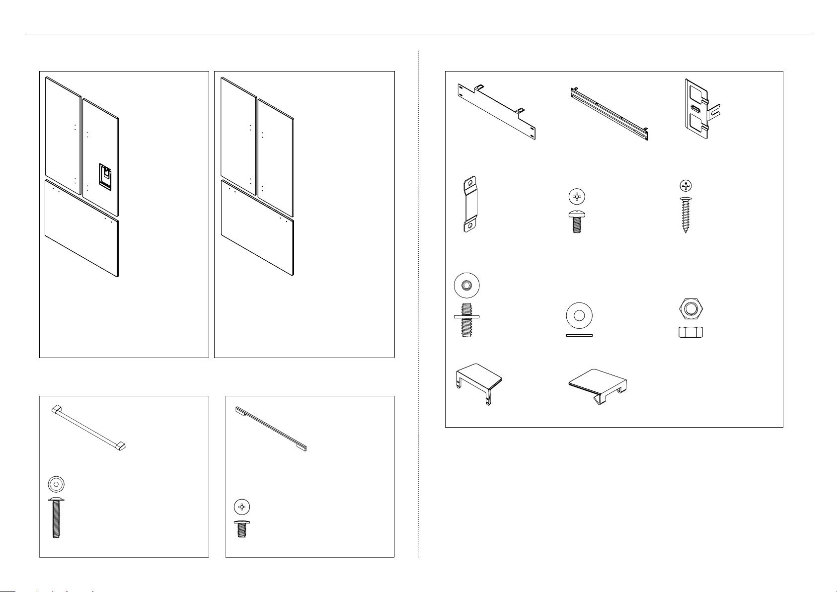
2 COMPONENTS LIST
Door panel set
Fisher & Paykel
(Stainless steel)
door panel set is
not included with
the refrigerator
and must be
purchased
separately.
Door panel set:
Non-Water dispensing French panel (1x)
Ice & Water French panel (1x)
Drawer panel (1x)
Model numbers:
RD3672 or RD3672U
Custom door panel
set is only applicable
for non-Water
dispensing models.
Customers can
supply their own
Custom door panel to
match their cabinetry.
Door panel set:
Non-Water dispensing French panels (2x)
Drawer panel (1x)
Door panel fittings — included with the refrigerator
French door hanging
bracket (2x)
Side strap (10x) M5x10 pan head Phillips
M8 stud (6x) M8 washer (6x) M8 nut (6x)
Drawer hanging bracket
(1x)
screw (10x)
Side bracket (10x)
#8x16 panhead Philips
screw (34x)
Door handle kit — not included with the refrigerator and must be purchased separately
Professional rounded door handle (3x)
M5x25 pan head socket screw (12x) M5x14 Mush Phillips SS (34x)
Contemporary square door handle (3x)
OR
Side cover (4x) Top cover (2x)
5
Page 8
d
L GF
F
g
e
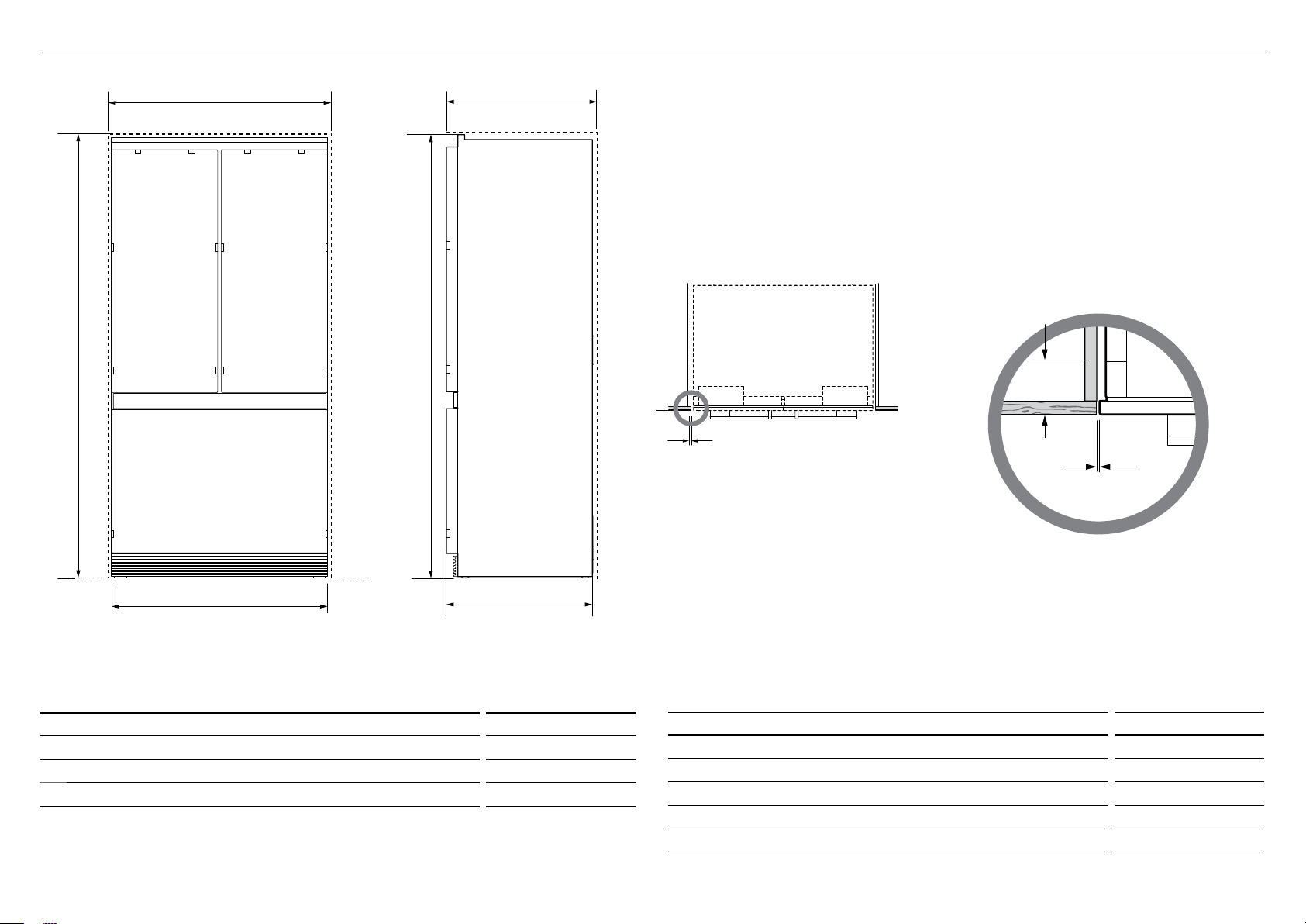
3 PRODUCT AND CAVITY DIMENSIONS
IMPORTANT!
f
A
For ease of installation, ensure cavity width is consistent
top to bottom and height isconsistent left to right.
g
Flush with
front of
cabinetry
h
b
FRONT VIEW PROFILE VIEW
PRODUCT DIMENSIONS inches (mm)
Overall height of product* 7127/32” (1825)
A
Overall width of product 3521/32” (890)
B
Overall depth of product (without door panels) 233/4” (603)
c
Includes mounted feet
*
6
C
PLAN VIEW
Frameless: Finished return top and sides
CAVITY DIMENSIONS inches (mm)
Overall height of cavity 72” (1829)
d
Overall width of cavity 36” (914)
e
Overall depth of cavity 25” (635)
f
Minimum cabinetry gap clearance from edge of product 3/16” (4)
g
Minimum required finished return min. 31/2’’ (89)
h
For integrated installation, ensure finished return dimensions are as shown.
g
Flush install
Page 9
4 CABINETRY OPTIONS
FRAMELESS CABINETRY
(Frameless: Aligns the product with the cabinetry)
Frameless Framed
FRAMED CABINETRY
(Framed: Aligns the product with the frame of the cabinetry)
Flush
installation
Proud
installation
Note: Drawings are only for reference and not the actual cavity width of the cabinetry.
7
Page 10

D
g
A
E
h
c b
5 DOOR PANEL DIMENSIONS
h
A
A
g
g
e
d
E
D
f
PROFILE VIEWFRONT VIEW
STAINLESS STEEL CUSTOM
DOOR PANEL DIMENSIONS inches (mm) inches (mm)
Height of each top door panel 44 7/32” (1123) 44 7/32” (1123)
A
Width of each top door panel 173/4” (451) 173/4” (451)
B
Gap between top door panels 5/32” (4) 5/32” (4)
C
Height of bottom drawer panel 23 15/32” (596) 23 15/32” (596)
D
Height from bottom of product to top of bottom drawerpanel 2715/32” (698) 2715/32” (698)
E
Width of bottom drawer panel 35 21/32” (906) 35 21/32” (906)
F
Gap between top door panels and bottom drawer panel 5/32” (4) 5/32” (4)
G
Depth of door panel (excluding handle) 3/4” (19) 5/8” – 3/4” (16 – 19)
h
Maximum weight of each top door panel
Maximum weight of bottom drawer panel
(with handle) 22 lbs (10kg) 22 lbs (10kg)
(with handle) 241/4 lbs (11kg) 241/4 lbs (11kg)
H
A
F
B
C
g
D
ISO VIEW
Note:
Optional Fisher & Paykel Stainless steel front panels. Model no. RD3672 (non-Water dispensing model) andmodelno.RD3672U (Ice&Water model).
Custom door panels to be manufactured and fitted by cabinetmaker min. 5/8” (16mm) – max. 3/4” (19mm) thickness.
Door handle kit is available as an optional accessory.
8
Custom door panels can be only be used for nonWater dispensing models.
Page 11

6 CUSTOM DOOR PANEL INSTALLATION DIMENSIONS
The drawings below apply to non-Water dispensing models only (RS36A72J). Dimensions apply for the preparation and installation of custom door panels.
For Dwg and Dxf files of the below panel preparation download the folder on thekitchentools.fisherpaykel.com.
15 15/32” (393mm)
23/16” (56mm)
Ø 3/32” (1.25mm) REF
12x Pilot holes recommended for bracket attachment.
(Do not penetrate front surface).
Ensure handle is mounted
29/16” (65mm) from inner edge
of panel to the center – this will
avoid interference with brackets.
4 31/32”
(126mm)
6 31/32”
(177mm)
24 31/32” (634mm)
26 31/32” (685mm)
40” (1016mm)
38 21/32” (982mm)
153/16” (386mm)
(129mm)
11/8”
(29mm)
5 3/32”
Ø 3/32” (1.25mm) REF
10x Pilot holes recommended
forbracket attachment.
(Do not penetrate front surface).
All measurements to be made
from inner bottom corner.
For the second panel mirror
and repeat dimensions using
inner bottom corner as the
reference point.
13/8” (35mm)
16 11/32” (415mm)
TOP PANEL – REAR VIEW
19 13/32” (493mm)
21 11/32” (542mm)
3 15/32”
(88mm)
Cut outs are located in attachment bracket for Fisher & Paykel handles only.
Iflocating custom handle in the shaded area above, ensure handle screw heads
arecounter sunk into back of panel to avoid interference with hanging bracket.
All measurements to be made
from top and centerline.
163/8” (416mm)
BOTTOM PANEL – REAR VIEW
9
Page 12

B
C
A
E
7 DOOR OPENING ROTATION
D
C
B
(FULL ROTATION)
DOOR CLEARANCE DIMENSIONS inches (mm)
Depth of door (widest opening) measured from front of door 175/16” (440)
A
Depth of drawer (open) measured from front of drawer, including handle 153/4” (400)
B
Depth of drawer (open) measured from front of drawer, excluding handle 14 3/16” (360)
C
Minimum door clearance* to adjacent wall (115° – full internal access) 1113/16” (300)
D
Minimum door clearance* to adjacent wall (90° – reduced internal access) 313/16” (100)
E
* Measured from front cabinetry edge.
A
Wall Wall
B
C
90° DOOR OPENING115° DOOR OPENING
E
A
For 90° door swing a hinge limiting pin is supplied with your
refrigerator. This pin fits in the boreholes of the top hinge
(refertoZ).
WARNING!
Before openining the doors, ensure that the appliance is stable.
Follow the correct instructions to avoid risks that can cause
serious injury or death.
Open door to 90°.
1
Align the hinge limiting pin vertically with the bore hole.
2
Use a hammer to drive the pin through the bore hole.
3
10
Page 13

!
WARNING!
Electrical shock hazard. Assume all parts are live.
Disconnect supply before servicing and installation.
Left side
of cavity
8 ELECTRICAL AND PLUMBING
!
215/16”
Floor
(75mm)
53/32”
(129mm)
411/32”
(110mm)
411/32”
(110mm)
Alternative electrical connection location
529/32”
(150mm)
529/32”
(150mm)
ELECTRICAL SPECIFICATIONS
Supply 115VAC, 60Hz
Service 10 amp circuit
PLUMBING SPECIFICATIONS
Supply 1/4” (6mm) hose or copper tubing*
Pressure min. 22psi (150kPa)
max. 120psi (827kPa) @ 68°F (20°C)
Note:
Electrical connection can be located in an adjacent cabinet to either side of the fridge or above the fridge cavity.
We recommend to use an isolating switch that is easily accessible to the user after the refrigerator is installed.
311/2”
(800mm)
Recommended area above
cavity for connections
Electrical
Plumbing
Electrical
Plumbing
Do not locate water or electricity in this area, keep clear of connections.
!
CAUTION: Central area can only fit electrical plug if it is placed within a recessed cavity.
* Water fittings kit – The standard refrigerator does not include water fittings. Standard Fisher & Paykel water fittings
kit are available (part number: 841301). These parts need to be purchased separately by the customer andcomply
with local regulations.
11
Page 14

Maximum distance of hose and power cord
8 ELECTRICAL AND PLUMBING
Power cord (excl. plug) – 31 1/2” (800mm)
12
LEFT HAND SIDE
Water inlet hose – 53 1/8” (1350mm) Water inlet hose – 83 1/2” (2120mm)
RIGHT HAND SIDE
Power cord (excl. plug) – 803/4” (2051mm)Power cord (excl. plug) – 803/4” (2051mm)
Page 15

9 BEFORE INSTALLATION
IMPORTANT!
Ensure your appliance is not exposed to any heat generating appliances eg cooktop, oven or dishwasher.
The refrigerator has front and rear rollers for moving forward and backward. Do not move the refrigerator sideways to avoid damaging the rollers or floor covering/surface.
The refrigerator must be installed by a qualified installer, or Fisher & Paykel trained and supported service technician to avoid faulty electrical connection and water leaks.
All connections for water, electrical power and grounding must comply with local codes and ordinances and be made by licensed personnel when required.
Avoid installation of the refrigerator/s under a ground fault circuit interrupter (GFCI).
Ensure the refrigerator is installed properly. Improper installation that results in refrigerator failure is not covered under the refrigerator warranty.
Check the installation location
Check the cabinetry
Check the dimensions of the cabinetry (width, depth, height, floor level, finished
alcovereturns).
Ensure that the ventilation openings in the cabinetry are clear of obstruction.
For integrated installation, a finished return of solid material is required across the top
andsides of the new or existing alcove.
It is recommended that the return should be at least 3 1/2” (89mm) deep across the sides.
Refer to ‘Cavity Dimensions’ prior to installation of the refrigerator.
Check the power supply connection
Ensure that there is a separate power outlet for each refrigerator.
Avoid sharing the power point with other appliances to prevent accidental switching off
ofthe refrigerator.
For power requirements, refer to the information on the serial plate. This is located athe
front right-hand side of the drawer when open.
Ensure your refrigerator is properly grounded (earthed).
Connect the refrigerator to the electrical supply (115VAC, 60Hz) with fitted plug and lead.
We recommend to use an isolating switch that is easily accessible to the user after the
refrigerator is installed.
Follow the National Electrical Code and all local codes and ordinances when installing
thisrefrigerator.
Check the water supply connection (for Ice & Water models only)
Your product must be installed by a qualified refrigerator installer as incorrect plumbing
canlead to water leaks.
Fisher & Paykel is not liable for damage (including water damage) caused by faulty
installation or plumbing.
Prepare the door panel set
The refrigerator does not include a door panel set.
Custom door panels are designed only for non-Water dispensing models.
To complete the integrated refrigerator for non-Water dispensing models, the
customershould supply their own custom door panel set.
– All the hardware required to mount the door panel sets to the refrigerator doors
issupplied with the refrigerator.
Door panel sets are available through your Fisher & Paykel dealer.
– Fisher & Paykel door panel sets are available (Stainless steel door panels)
modelnumbers: RD3672 and RD3672U.
Handle sets are optional for custom door panels and can also be purchased through
yourFisher & Paykel dealer.
Check your refrigerator
Ensure that your refrigerator is the correct model as per your order.
Ensure that the packaging is not damaged upon delivery.
Check that the components and install kits are complete.
13
Page 16

!0 ATTACH ANTI-TIP BRACKET
IMPORTANT!
Ensure the refrigerator door is closed when rolling into cabinetry.
DO NOT attempt to open the door until refrigerator is fully installed.
The anti-tip bracket and fittings supplied must be fitted to the wall of finished enclosure
to withstand 220 lbs (100kg) load.
Ensure that anti-tip bracket is installed correctly to prevent the refrigerator tipping
forward when door is open.
Project the end of the above finished enclosure to the
1
center of the back wall and measure 11/4” (31mm)
vertically from the projection line (A).
– This will locate the contact surface between
thebracket and the top surface at the back end
oftherefrigerator.
23/8” min.
(60mm) overlap
A
Mark the screw locations of the anti-tip bracket on the
2
wall based on the most central wall stud (B).
– If there are no wall studs, the bracket can be
installed to solid brick walls with masonry plugs.
(However,notrecommended to be used on
perforatedbrick or hollow concrete bricks.)
Bracket
For wooden/plaster board wall installation:
4
Fix the bracket to the wall #10x40 pan head
Phillipsscrews (4x), and screw tightly (C).
For solid wall installation:
5
Hammer masonry plugs (4x) into the wall until flush.
Fix the bracket to the wall with #10x40 pan head
Phillips screws (4x), and screw tightly (D).
WARNING!
Read the following reminders before fastening with masonry plugs and/or screws:
Ensure the screws avoid electrical, gas and water conduits.
Ensure the surface of the bracket is fastened to withstands a 220.5 pound (100kg) load.
Ensure light-weight masonry material such as cinder block and new concrete
(nocuringtime) are not used in installation.
Do not use metallic materials that may corrode, stain and/or damage the enclosure.
IMPORTANT!
When positioning the refrigerator in the cabinetry,
ensure that the bracket overlaps the refrigerator
byaminimum 2 3/8" (60mm) for a secure hold.
23/8” min.
(60mm) overlap
C
Bracket
If the minimum 2 3/8" (60mm) overlap cannot be
achieved, installa solid spacer to the wall stud behind
the bracket.
23/8” min.
(60mm) overlap
B
Drill Ø 1/4” x 13/8” (Ø 6mmx35mm) deep screw holes
3
tothe marked locations.
14
D
Spacer
Bracket
Page 17

!1 REMOVE HINGE END CAPS
150
C
180
L
O
P
150
C
O
P
P
WARNING!
Be careful when working with the refrigerator outside of the finished enclosure.
Ensure that the refrigerator is secured to prevent tipping forward.
Tippingofrefrigerator can lead to serious injury or death.
Open the refrigerator French doors carefully
1
and remove the left hinge end cap.
Hold onto the corner of the end cap,
firmlypush to the right to disengage
securing hook and pull down (A).
Pull cap gently towards the left hinge
2
to remove (B).
A
Secure M8 studs into the refrigerator doors,
4
ensure the open end faces the top and the
studs go all the way in.
Repeat this process for all refrigerator doors.
Reserve end hinge cap for later
installation.
Remove the right hinge end cap.
3
Pressonthe center of the cap and
pushtowards the right hinge to remove.
Reserve end hinge cap for later installation.
Loosely screw (1–2 turns) M5x10 pan head
5
Phillips screws into doors.
B
Repeat this process for all refrigerator doors.
1 – 2 turns
15
Page 18

!2 CONNECT TO WATER AND ELECTRICAL SUPPLY
IMPORTANT!
The water connection instructions below are intended only for the professional installer.
Water fittings are not included in the refrigerator and must be purchased separately.
Fisher & Paykel water fittings are available (part number: 841301) and comply with local regulations.
Ensure the refrigerator is NOT plugged into a power supply.
Ensure there is enough tubing for the water connection and to pull the refrigerator outforservice, if required.
REAR VIEW
Uncoil the 1/4” (6mm) water tubing and thread one end through
1
the opening intherear cover until it exits the front.
B
C
A
FRONT VIEW
At the front of the product, dislodge the PRV.
2
Grasp the PRV from the clips by pulling ittowards you (A).
16
Firmly insert water tubing into the PRV. The tube should push in at least
3
5/8” (16mm) before reaching the stop. Once inserted, pull gently on tubing
to ensure it is locked in(B).
Secure the connection by attaching the locking key in between the
PRVand water tubing (C). Mount the PRV back into the clip.
Page 19

!2 CONNECT TO WATER AND ELECTRICAL SUPPLY
IMPORTANT!
Ensure water tubing is routed away from any sharp objects, sharp corners, and not in a location where it can be kinked or squashed.
Beware of kinking the tube as this will stop water flow.
Ensure a firm contact is observed as the refrigerator engages the anti-tip bracket, 23/8” min. (60mm) overlap.
Move the refrigerator in front of the cabinetry close enough to allow access behind
4
for power and water connections.
At the back of the refrigerator, cut the water tube to a suitable length for connecting
to the water outlet. Ensure there is enough tubing to pull the refrigerator out for
service, if required.
Assemble the following water fittings onto the other end of the water tube.
5
Insert tube Compression
sleeve
Compression
nut
Final water tube connection
Water tube
NOTE:
If using a braided water line hose (not
supplied), connect an adaptor to one
end of the hose before inserting into
the PRV.
Fasten the faucet connection to the cold water supply. Take care not
6
to over-tighten the faucet connection. Turn isolating faucet on and
check that all connections are dry and free of drips.
Connecting power
7
Attach the power cord clip to the back of your refrigerator
Connect the refrigerator to the electrical supply (115VAC, 60Hz
with thefitted plug and lead, and turn on. Ensure the refrigerator
isconnected to its own isolating switch.
Ensure excess power cord length is secured onto the clip (D).
When pushing the refrigerator into position, take care not to roll
over ordamage the power cord and/or water tubing.
D
17
Page 20

!3 ALIGN YOUR PRODUCT INSIDE CABINETRY
IMPORTANT!
Ensure that all four corners of the refrigerator are supported firmly onto the floor to
eliminate any movement.
Installing the refrigerator on a soft, uneven, or not level floor may result in twisting
oftheproduct and poor door sealing.
Raise the refrigerator using a 7/16” (11mm) hex socket or 3/16” (4mm) hex key.
Oneturnof height adjusting nuts is equivalent to 1/16” (1mm) height travel.
Note: Maximum turn is 13/16” (20mm).
Use low torque setting to avoid damage to height adjustment system.
Failure to achieve flushness across all sides greater than 1/16” (1.5mm) can lead to
difficulties achieving final alignment. Final alignment will be achieved once door panels
have been installed and the refrigerator is pushed back to sit flush with cabinetry.
Turn the front and rear adjustment nuts
1
(A) using a hex key to extend the feet
until it engages the floor.
– Clockwise turn raises the height
and counter-clockwise turn lowers
the height.
Continue turning the adjusting nuts
2
alternately between front and rear feet
to align the front of the doors top to
bottom on both sides, and until you
achieve the correct alignment.
– Depending on your installation
design, alignment may be flush
with your adjacent cabinetry or
your framework.
Place a ruler on the front of the product (B) to check flushness
C
3
top and bottom, left and right. Check the gaps between
refrigerator and adjacent cabinetry are even on both sides (C).
– This step will help ensure the refrigerator is level with the
adjacent cabinetry.
Gently push the front of the product to check the stability.
4
Place a ruler on the
front of the product to
check flushness top and
bottom, left and right.
B
AA
18
Rear roller adjustment
Front roller adjustment
Page 21

!4 INSTALL WATER FILTER AND TOE KICK GRILLE
IMPORTANT!
The water filter head must be firmly pushed into the product and secured. incorrect installation can lead to water leaks.
Installing the water filter
Remove the plastic wrapping of the new filter.
1
Pull the freezer drawer out slightly and insert the filter into the casing at the bottom
2
left corner of the refrigerator. Ensure the filter handle is positioned vertically (A).
Push the cartridge firmly inside the casing all the way into the filter head.
3
A
FRONT VIEW
Align the filter removal tool over the filter handle and turn
4
90° clockwise to tighten (B). Remove filter removal tool
and close the freezer drawer.
Installing the toe kick filter and grille
Remove filter from inside the product. Fit the filter onto the
6
rails and push to the rear until it clips securely (C).
C
Align clips on the back of the grille with openings on front face of plinths.
7
Push grille firmly onto refrigerator until the clips engage (D).
B
Filter in locked position
Flushing the water filter
Before turning on your automatic ice maker, the water filter must be flushed to remove
5
any impurities or trapped air in the water tank and filter system. Refer to the user guide
‘Operating instructions — Automatic ice maker’ for more information.
D
19
Page 22

!5 ASSEMBLE DOOR PANEL SET
The assembly of Fisher & Paykel (Stainless steel) door panels and custom door panels are outlined below.
Toprotect the finish of the Fisher & Paykel Stainless steel door panels, leave protective film on the panels
when hanging and remove film only when installation is complete.
If using custom door panels, ensure they are prepared as per ‘Custom door panel installation dimensions’ section.
French door panels
Mounting handle (A)
1
For Fisher & Paykel door panel sets, remove
theplastic plugs from the handle holes (4x).
Alignthe handle to the holes and secure with
M5x25 pan head socket screws (4x).
For custom panels, ensure the handle is secured
29/16” (65mm) from the inner edge of the panel
to the center. This will avoid interference with the
bracket installation.
Hanging bracket (B)
2
For Fisher & Paykel door panel sets, align the
bracket to the holes and secure with M5x14 mush
Phillips SS screws (4x).
For custom panels, secure bracket with #8x16 mush
washer screws (4x).
Side brackets and straps (C)
3
For Fisher & Paykel door panel sets, align bracket
and strap to the holes on the side of the panel and
secure with M5x14 mush Phillips SS screws (2x).
For custom panels, secure bracket with #8x16 mush
washer screws screws (2x).
Repeat this process for
allbrackets and straps,
andremaining French
door panel.
Drawer door panel
Mounting handle (D)
4
For Fisher & Paykel door panel sets, remove
B
the plastic plugs from the handle holes (4x).
Align the handle to the holes and secure with
M5x25 pan head socket screws (4x).
For custom panels, ensure handle screw heads
are counter sunk into the back of the panel to
avoid interference with hanging bracket.
D
A
Hanging bracket (E)
5
For Fisher & Paykel door panel sets, align the
bracket to the holes and secure with M5x14
mush Phillips SS screws (6x).
For custom panels, secure bracket with #8x16
mush washer screws (6x).
Side brackets and straps (F)
6
For Fisher & Paykel door panel sets, align
bracket and strap to the holes on the side of
the panel and secure with M5x14 mush Phillips
SS screws (2x).
For custom panels, secure bracket with #8x16
mush washer screws (2x).
Repeat this process for all brackets
andstraps.
E
20
C
F
Page 23

For Fisher & Paykel Stainless steel door panels only.
Remove the external display module
1
from inside the product.
Thread the display harness through the
door panel cavity. Ensure the grommet
is engaged.
Angle top display tabs into the door panel.
2
Ensure the harness is free of pinching.
Firmly push against bottom display tabs
and insert into the door panel until you
feel it clip securely. Ensure the display is
flush with the door panel.
!6 HANG ICE & WATER DOOR PANEL
Connect display harness onto the refrigerator door
5
by inserting firmly until you feel it clip securely (B).
On the external display, enable the dispenser lock,
this will help prevent any water from dispensing
during water connection. To lock, press the
button for 4 seconds. The LED above the button
will illuminate.
B
Remove water tube from holder
3
on the refrigerator door.
Hang door panel onto M8 studs.
4
Ensure the panel is free to pivot
for water connections (A).
A
Push the water tube firmly into the spigot behind the
6
door panel until the marked line is not visible.
Ensure the water tube is routed away from any sharp
objects, sharp corners, and not in a location where it can
be kinked or squashed when the door panel is secured,
(as this will stop water flow).
To secure door panel, refer to ‘Hang non-Water
dispensing door panels’.
21
Page 24

For Fisher & Paykel Stainless steel door panels only.
IMPORTANT!
Remove the protective film before hanging
thedoor panels.
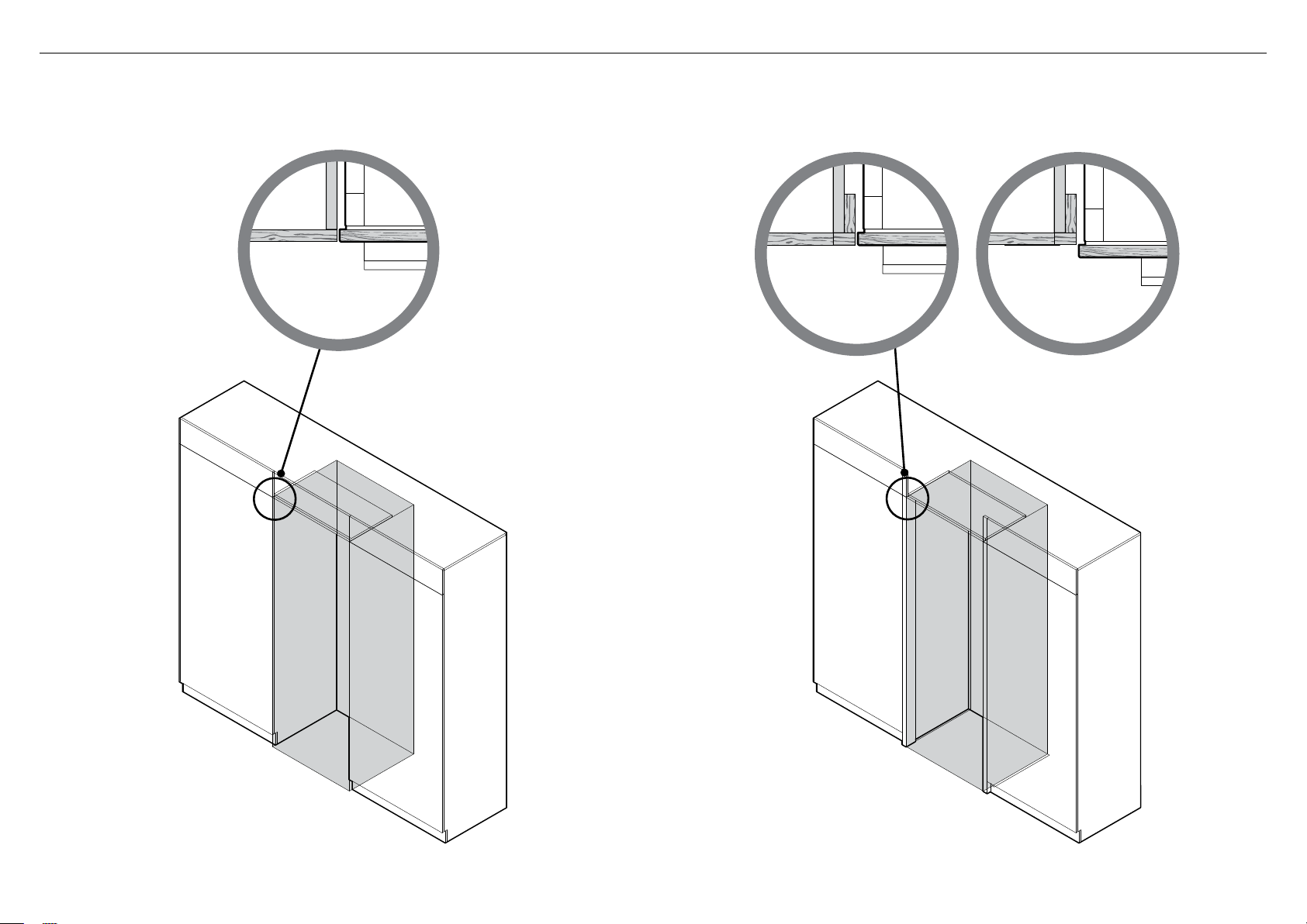
!7 HANG NON-WATER DISPENSING DOOR PANELS
Hang all door panels onto M8 studs and
1
alignthe side bracket forks onto the
refrigeratordoor (A).
– Ensure the forks are positioned around
thebody of the side screws (M5x10 pan
head Phillips screw).
Push the product until the door panels are flush.
2
– Depending on your installation design this
will be flush with your adjacent cabinetry
or your framework.
Place a ruler on the front of the product to check
3
flushness top and bottom, left and right (B).
Ensure the gap between the top of the door
4
panel and the top cabinetry is no greater than
1/4” (7mm).
– To reduce this gap, raise the product
byturning all four adjustment nuts the
same number of turns.
IMPORTANT!
Failure to follow these steps can lead to
difficulties in door panel adjustment and
cosmetic cap fitment.
Lock top inner panel side screws to allow
5
opening the doors without affecting
adjustment. (Open the left door to lock the
right screws and vice versa (C).)
A
D
E
All door panels have
6
full axis adjustment to
ensure they are flush
with adjacent walls.
To adjust the height
of each panel, turn
the stud clockwise
to raise or counterclockwise to lower
the door panel (D).
Once satisfied with
7
the alignment, secure
M8 studs with M8
washer and M8 nut
(E). The top of the
stud must remain
below the top face of
the door panel.
F
22
B
Secure side bracket forks by tightening
C
Place a ruler on the
front of the product to
check flushness top and
bottom, left and right.
8
side screws (F).
Repeat this process for all door panels.
Note:
For depth adjustment loosen side screws x4,
adjustpanels and then retighten oncesatisfied.
Further adjustment of door panels can be achieved
by removing door panels then loosening the fixing
screws for the hanging bracket and moving the
bracket sideways to suit.
Page 25

!8 ATTACH TOP TRIM AND HINGE END CAPS
P
150
C
O
P
A
B
Secure the top trim to the ceiling of the enclosure
1
with screw x1 (#8 x 16 mush washer screw).
Repeat this process on the opposite side.
Replace the left hinge end cap. Align hinge cap to the product,
2
press and firmly slide the cap to the right (refer to A).
Hold onto the corner of the end cap, firmly push up and to the left
to engage securing hook. Ensure cap is flush with the product.
Replace right hinge end cap. Align hinge cap to product, press and
3
firmly slide the cap to the left (refer to B). Ensure cap is flush with
the product.
23
Page 26

If applicable, remove any remaining protective film
1
on your door panels.
A
!9 ATTACH COVERS AND DOOR/DRAWER TRIMS
F
B
Open the refrigerator French doors, firmly push top cover (A)
2
over the top studs.
Open the refrigerator French doors, firmly push side cover (B)
over the side studs.
C
E
Press the dual adhesive tabs together to form pairs (E) and remove
4
the adhesive backing on one side only.
Press firmly to install on the underside of the drawer top trim in the
indicated locations (F).
D
Door side trims
3
Install the side trims by inserting into the panel gaps on each side of the door(s) (C).
Align the trim to the top of the door and press evenly into the panel gap until fully
seated (D).
24
Drawer side trims
5
Install the side trims in the same manner (refer to step 3).
Drawer top trim
6
Remove the remaining adhesive backing from the dual adhesive tabs.
Locate the trim against the back surface of the panel and press down
firmly. Ensure the trim is fully seated against the drawer surface.
Page 27

@0 ATTACH CABINET SIDE TRIMS
IMPORTANT!
Before installing your refrigerator, ensure the dimensions of the finished enclosure are
correct for your refrigerator following the‘Product and cavity dimensions’ sections.
Side trim
bracket
Discard
Break off the datum lip to each side trim bracket and discard (A).
1
Repeat for all side trim brackets.
A
Side trim
Top view of side trim engaged
correctly in side trim bracket
B
IMPORTANT!
Each bracket has two engagement points for the side trim to locate.
Ensure the trim is engaged in both points (B).
Position 3 side trim brackets onto each side trim.
2
Note: Measure from the top of the trim, with the shorter lip at the bottom.
Repeat this process for the remaining side trim.
B
25
Page 28

@0 ATTACH CABINET SIDE TRIMS
Spring clip
Side trim lip
D
Top view of spring clip correctly inserted
between side trim and side trim bracket
E
IMPORTANT!
Ensure spring clip is correctly oriented with the open loop facing the side trim lip.
G
F
IMPORTANT!
Ensure the side trim is positioned as high as it will go.
Insert the spring clip into the gap between the side trim and side trim bracket,
3
orientation as shown in figures (D) and (E).
Repeat this process for the remaining side trim.
26
Open refrigerator doors. Place the assembled side trim with brackets and spring
4
clips against the alcove side wall with the shorter lip facing the bottom (F).
Push the side trim at each bracket location until there are no visible gaps
between the trim and cabinetry (G).
Repeat this process for the remaining side trim.
Page 29

TO BE COMPLETED BY THE INSTALLER
All models
Check all parts are installed.
Ensure the refrigerator is level.
Ensure the refrigerator is securely fastened to the cabinetry with the
supplied anti-tip bracket and fittings.
Ensure the doors/drawer can open and close freely with no resistance
from surrounding cabinetry.
Ensure hinge limiting pin is fitted for 90° door swing.
Ensure all internal and external packaging is removed from the
refrigerator before use.
Ensure a manual ice maker cycle has been forced.
Ice & Water models only
Ensure the water filtration system has been flushed.
@1 FINAL CHECKLIST
Complete and keep for safe reference:
Model
Serial No.
Purchase Date
Purchaser
Dealer Address
Installer’s Name
Installer’s Signature
Installation Company
Installation Date
FISHERPAYKEL.COM
© Fisher & Paykel Appliances 2018. All rights reserved.
The product specifications in this booklet apply to the specific products
and models described at the date of issue. Under our policy of continuous
product improvement, these specifications may change at any time. You
should therefore check with your Dealer to ensure this booklet correctly
describes the product currently available.
27
Page 30

 Loading...