

Fisher & Paykel OD301, OD301MV1-87818, OD301MV1-87893, OD301MV2-87930, OD301MV2-87932 Installation Guide
...
PAGE1OF8
P/N 545855E
DATEOFISSUE
11 / 2003
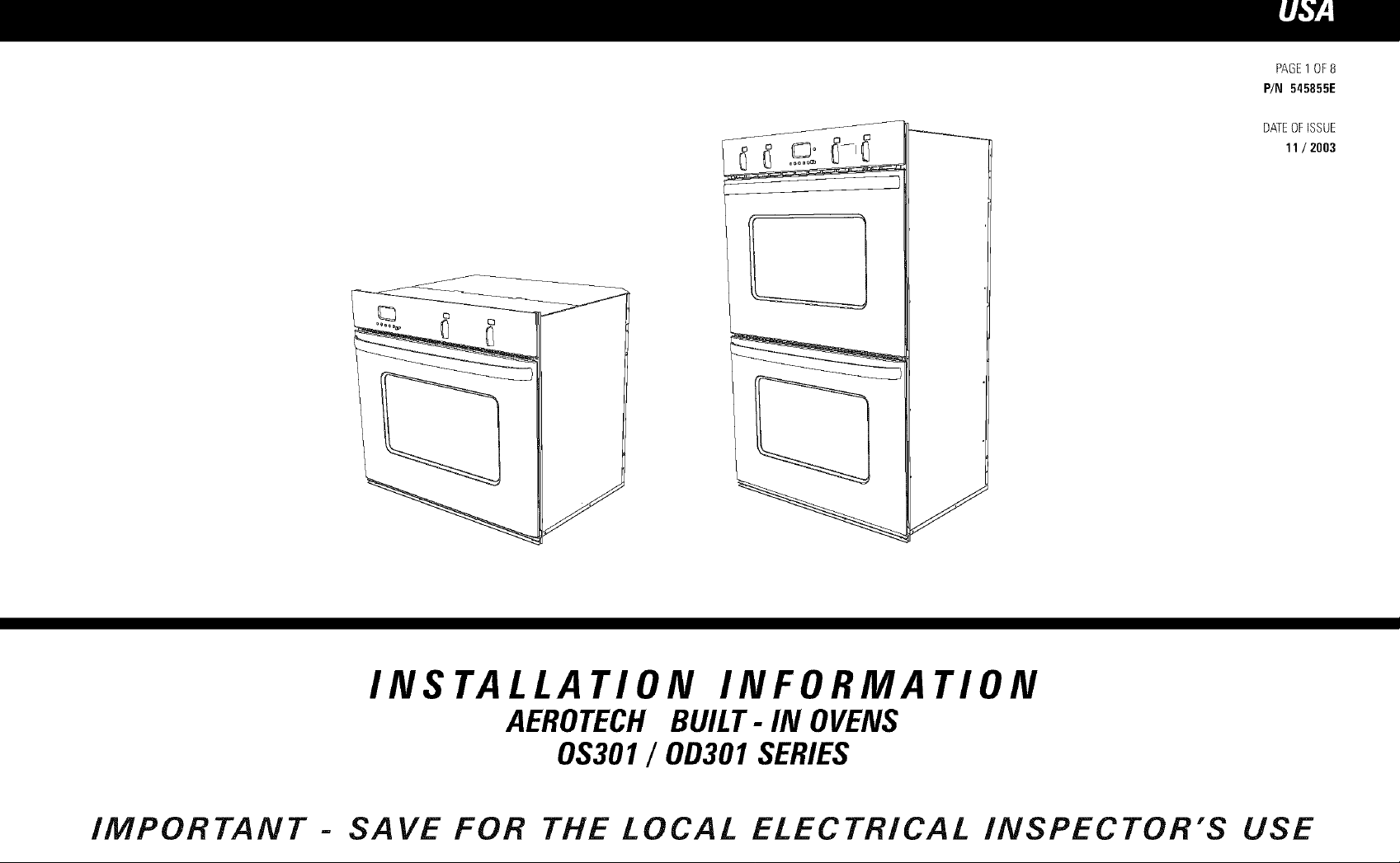
INSTALLATION INFORMATION
AEROTECH BUILT- IN OVENS
0S301 / 0D301 SERIES
IMPORTANT- SAVE FOR THE LOCAL ELECTRICAL INSPECTOR'S USE
BEFORE YOU START
Correct installation is the responsibility of the customer.
Ensure that the installer is properly qualified to install this oven.
= Make surethat the oven is locatedaway from anystrong and/orhot drafts of air,
• Thecabinetopeningdimensionsspecifiedare the absoluteminimum. Thesedimensionsallow a clearance
of upto 1/4"(6mm).
° Theproductmust beelectrically grounded.See"ElectricalConnection"for details,
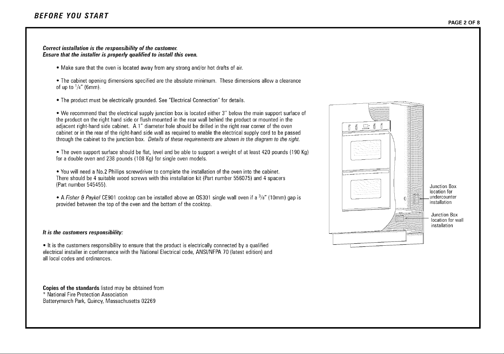
* We recommendthat the electricalsupplyjunction boxis locatedeither3" belowthe mainsupportsurfaceof
the productonthe right handsideor flush mountedinthe rear wall behindthe productor mountedin the
adjacentright-handsidecabinet. A 1"diameterholeshouldbe drilledin the right rearcorner of the oven
cabinetorinthe rearofthe right-handsidewall as requiredto enablethe electricalsupplycordto be passed
throughthe cabinetto the junction box, Detailsofthese requirementsareshownin thediagramto the right.
* Theoven supportsurfaceshouldbeflat, leveland beableto supporta weight of at least 420 pounds(190 Kg)
for a doubleovenand 238 pounds(108 Kg)for single ovenmodels,
• Youwill needaNo,2 Phillipsscrewdriverto completethe installationof the oven intothe cabinet.
Thereshouldbe4suitablewood screwswith this installationkit (Partnumber556075)and4 spacers
(Partnumber 545455),
* A Fisher8 PaykelCE901cooktopcan beinstalledabovean 0S301single wall ovenif a 3/8" (10mm)gap is
providedbetweenthe top of theovenandthe bottomof thecooktop.
It is thecustomersresponsibility:
PAGE 2 OF 8
Junction Box
location for
undercounter
--installation
Junction Box
-- location for wall
installation
• It isthe customersresponsibilityto ensurethat the product is electricallyconnectedbya qualified
electricalinstallerin conformancewith the NationalElectricalcode,ANSI/NFPA70(latest edition)and
all localcodes andordinances,
Copiesof the standardslisted may beobtainedfrom
* NationalFireProtectionAssociation
BatterymarchPark,Quincy,Massachusetts02269

PRODUCT DIMENSIONS
28 1/4" (718mm)
PAGE 3 OF 8
28 1/4" (718mm)
.\
AE
E
O
,\
E
O
LO
v
_U --_ US
LO
v
%
Z-
51
29 3/4" (757mm)
......
0S301
0D301
29 3/4" (757mm)
o
p,..
F,
.C..
%
-.T.
p..
EA
E

PROUD DiMENSiONS RECESSED DiMENSiONS
PAGE 4 OF 8
Minimum Distance
Under Benchtop
for Single
2 3/4" (70ram}
TOP VIEW
TOP VIEW
Minimum Distance
Under Benchtop
for Single ovens
2 314"{70ram)
._
= o
__
etN/idt h
-4r_
, _etWidth

PREPARING THE OVEN ELECTRICAL REQUIREMENTS
PAGE 5 OF 8
Unpacking the oven
Donot usedoorhandlesor anypart of the controlpanel forliftingthe product.
Beforethe productis lifted, theoven doorsandracks are to beremoved.
-] ARNING: Extremecare is to betaken when liftingthe productas it
is veryheavy. Failureto do somay resultin injury.
1. Carefullylaythe product on its back. Removethe externalwrappingandthe
bottom polystyreneprotectorandpallet. Standthe productupand removeall
other polystyrenepackaging.
2. Removethe ovendoors.This isdoneby:
• Openthe ovendoorfully.
• Liftthe catcheson bothofthe hingesovertowards you ontothe hooks
of the hingearm (seepicture below).
• Raisethe doorslightly,holdingon eitherside nearthe handle,making
surethat the clips stay on the hooks.
WARNING: Do notlift the doorout bythe handleas thismay cause
damageto the product.
• Liftthe doorout.
Door Hinge
Door
Theelectricalvoltageandfrequencythat is correctfor this ovenis stated onthe
serialnumberplate locatedinsidethe top vent. It isthe customerresponsibilityto
ensurethat this ovenis connectedto the correctelectrical supply.
WARNING :Theoven mustbe connectedto a permanentand
groundedsupply.
Maximum currentdraw: MaximumLoad:
Double: 3&2 amps 9.2 kW
Single: 21 amps 5.1 kW
CONNECTOVENWITH COPPERWIREONLY
• Theflexible armouredcableshouldbe connecteddirectlyto the junction box.
• Donot cut the conduit,
• A U.L.listedconduit connectormust be providedat the junction box.
• Donot groundto a gaspipe.
• Donot haveafuse in the groundingor neutralcircuit.
• Fusebothsidesof the line.
• Atime delayfuseor circuit breakeris recommended. If usinga time delay
fuse,thenfuseboth sidesofthe line.
• Flexiblearmouredcablefrom the applianceshouldbe connecteddirectlyto
the junction box.
--_ ARNING: Do notdisengagethe hingehookswhen thedoorhas
been removedas theyarediffercult to re-engage.
3. Removethe wire shelvesand oventrays by slidingthem out. Useboth hands
to removeeachitem. Removethe cardboardpackagingfrom the ovencavity.
• Connectdirectlyto the fused disconnect(orcircuit breakerbox)throughflexible,
armoredor non-metallicsheathed,coppercable(with groundingwire).
• If codespermit andaseparategroundingwire is used,it is recommended
that a qualifiedelectriciandeterminethat the groundingpathand wire gauge
is in accordancewith local codes.
• Donot usean extensioncordwith this appliance.

ELECTRICAL CONNECTION
This oven is manufactured with white (neutral) power supply wire and a cabinet-connected green grounding wire taped together.
Feedthe ovencablethrough the openingin the cabinet.Makethe electrical connectionfollowing thesteps appropriatefor your installation,
1. Disconnectthe power supply.
------_WARNING : Failureto disconnectthe powersupplymayresult indeathor injury.
PAGE 6 OF 8
2. Removethejunction boxcover.
3. Connectthe ovencableto the junction box throughthe U.L-listed conduit connector,
4. Connectthe two blackwirestogetherwith twist-on connectors,
5. Connectthe two redwires togetherwith twist-on connectors.
6. Connectelectricalconnectionaccordingto localcodesand ordinances,
If localcodesPERMITconnectingcabinet-groundingconductorto neutralwhite wire in
the junctionbox:
7. Connectthe factory-crimpedgreenandwhite ovencablewires to the
neutral(white) wire inthe junction box,
8. Replacethe junctionboxcover,
0,9
If localcodesDO NOTPERMITconnectingcabinet-groundingconductorto neutral
(white) wire injunctionbox:
7. Separatethe factory-crimpedgreenandwhite ovencablewires,
8. Connectwhite ovencablewire to neutral(white) wire in junctionbox.
9. Connectthe greengroundingoven cablewire to a groundedwire in the junction box,
10. Replacethejunction box cover.
0,9 If connectingto afour-wire electrical system:
7. Separategreenandwhiteoven cablewires.
8. Connectwhite ovencablewire to neutral(white) wire in junctionbox.
9. Connectthe greengroundingoven cablewire to the (green)groundingwire inthe junction box.
Donot connectgreen groundingwire to neutral(white)wire injunction box,
18. Replacethejunction boxcover,
Cable from
JrlnuCt_i n box po_ _pply wires
grounding oven wires
- factory crimped _ " " - ! nector
Cable from
junction box
red wires
green grounding
wires- oven wire
factory crimped
po_ upply
white wires
U,L. - listed
conduit connector

A TTA CHMEN T
1. Feedthe electricalsupplycableinto 1" holecutout of the rear
of the oven cabinet.
WARNING : Extremecare is to betakenwhen liftingthe productas it
isvery heavy. Failureto do somay resultin injury.
Slidethe productintothe ovencabinet,pushingthe product betweenthe two oven
cavitiesor bythe edges ofthe oven cavity.
PAGE 7 OF 8
Make surethat the electricalsupplycablecan dropstraightdown usingthe
recesson the rearof theoven intothe cable entryholeinthe rear of the oven
cavity. If the productdoesnotsitflushwith the frontof the oven cabinet,
makecertainthatthe electrical supplycable hasnotjammedbehindthe
product. Ensurethe bottomventis notblockedoff or damaged.
,
Securelyfastenthe oven to the cabinetusingthe screwsprovided. Insert the
screws throughthe holes inthe sideextrusionsandthroughthe spacersplaced
betweenthe sideextrusion andthe kitchenjoinery(seediagramopposite).
Do notover tightenscrews.
,
Replacethe oventrays and wire shelves. Theshelveshavea
front and back. Insertthem intothe ovenin the correctwayto
ensurethat the 'stop-lock' featureofthe shelf works correctly
(seediagramapposite).
4,
Refitthe ovendoors. This isdone by:
Placeboth upperhingearms inthe top slots andboth lower
hingearmsinthe lowerslots.
Pushthe hingesasfar asthey will go until the slot inthe lower
armlocatesinthe hingesupport.
Lowerthe doorgently. Pushthe catchesaway from youoff the
hooks. Makesurethat they disengageproperly.
Raisethe doorslightlyand ensurethe catchesarereleasedfrom
the hooks. Thedoorcan now be closed.
\ J
/
--_ WARNING : Donot standor sit onthe doors.

CHECKLIST TROUBLE SHOOTING
PAGE 8 OF 8
1. Make sureproductis levelandsecurelyfitted to the cabinetryand
both ovendoorsopenandclosefreely.
2. Make sureallthe internalpackaginghasbeenremovedfrom the oven cavity.
3. Make surealloven ventsand openingsareclearandare freeof anyobstruction.
F_ WARNING :
4. Turnthe powerto the ovenon. Theclock shouldlight up and blink12:00pm.
5. Set the clockto the currenttime.
6. Turnthe ovenfunctionswitch to 'Bake'and theoven tempswitch to 350' F.Air
[_ WARNING :
7. Turnboththe ovenfunction switch and oventemp switch backto off andrepeat
Failureto dosomay resultin a fire or poorproductperformance.
shouldblow out ofthe ventat the bottomof the oven. Insidethe ovencavity allthree
ovenlights shouldcomeon. After 5 minutesopenthe ovendoorandthe air inside
shouldfeel warm. Thetop elementshouldbe glowing redandthe bottomsurfaceof
the ovencavity shouldfeel warm to lightly touch.
Donottouchthetop elementas this may resultin injury.
for the other ovenif product isa double.
IF THEOVENDOESNOTOPERATE:
* Checkthatthe circuit breakerhas nottripped orthe fuseblown.
• Makesurethatthe electricalconnectionshavebeencorrectly made.
• Makesurethat power is beingsuppliedto the oven.
, Makesurethe voltageis correctacrossallphases.
IF YOUNEEDASSISTANCE:
• If a fault occursconsultthe ProblemSolverSectionof yourUserGuidebook.
• CallyourlocalCustomerCarerepresentativeon 1-8889FNPUSA(1-8889 367 872).
• Pleasehavethe modelandserialnumber ofyour productreadyforthe
CustomerCarerepresentative.
 Loading...