

Fisher & Paykel OB60 Series Installation Instructions And User Manual

Built-in oven
Installation instructions
and User guide
NZ AU GB IE
OB60 electronic and pyrolytic models


1
Safety and warnings
2
Installation instructions
5
ELECTRONIC MODELS
Using your oven for the first time
11
Using the control buttons
12
Selecting the cooking functions
14
Selecting the temperature
15
Cooking functions
16
Manual and automatic cooking
18
Error codes
19
Care and cleaning
20
PYROLYTIC MODELS
Using your oven for the first time
30
Clock and timer
31
Selecting the functions and temperature
32
Cooking functions
33
Automatic cooking
35
Care and cleaning
36
Warranty and service
42
Important!
SAVE THESE INSTRUCTIONS
The models shown in this User Guide may not be available in all markets and are
subject to change at any time. For current details about model and specification
availability in your country, please go to our website www.fisherpaykel.com or
contact your local Fisher & Paykel dealer.
Contents
2
Safety and warnings
WARNING!
Cut Hazard
Take care - panel edges are sharp.
Failure to use caution could result in injury or cuts.
WARNING!
Electrical Shock Hazard
Always disconnect the oven from the mains electricity supply before
carrying out any maintenance operations or repairs.
Failure to do so may result in death or electrical shock.
Important safety precautions
To avoid hazard, follow these instructions carefully before installing or using this product.
Please make this information available to the person installing the product as it could reduce
your installation costs.
This oven is to be installed and connected to the electricity supply only by an authorised person.
If the installation requires alterations to the domestic electrical system call a qualified electrician.
He should also check that the socket cable section is suitable for the electricity drawn by the oven.
The oven must be earthed.
To connect the oven to the mains, do not use adapters, reducers or branching devices as they can
cause overheating and burning.
Installation must comply with your local building and electricity regulations.
Failure to install the oven correctly could invalidate any warranty or liability claims.
Before you install the oven, please make sure that
A suitable disconnection switch is incorporated in the permanent wiring, mounted and positioned
to comply with the local wiring rules and regulations. The switch must be of an approved
type installed in the fixed wiring and provide a 3 mm air gap contact separation in all poles in
accordance with the local wiring rules.
In Australia and New Zealand, a switch of the approved type with a 3 mm air gap must be
installed in the active (phase) conductor of the fixed wiring.
The location of the oven connection socket (if fitted) is outside the cavity if the product is flush to
the rear wall.
The electrician allows at least 1.5 m (and not more than 2 m) free length of connection cable
within the cavity for ease of installation and servicing of the product. The mains cable should not
touch any hot metal parts.
Installation
3
The oven will rest on a surface that can support its weight.
The benchtop and oven cavity are square and level, and are the required dimensions.
The height from the floor suits the user.
The oven door can open fully without obstruction.
If the supply cord is damaged, it is replaced by the manufacturer, its service agent, or a similarly
qualified person in order to avoid a hazard.
When you install the oven
Do not seal the oven into the cabinetry with silicone or glue. This makes future servicing difficult.
Fisher & Paykel will not cover the costs of removing the oven, or of damage caused by this
removal.
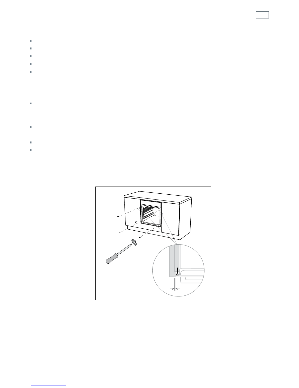
Use the supplied screws to secure the oven to the cabinetry. Do not over-tighten the screws. (See
Fig. 1)
Do not stand on the door, or place heavy objects on it.
Do not lift the oven by the door handle.
Safety and warnings
Figure 1 Securing the oven to the cabinetry
2.5 mm
4
Operation
Your built-in oven has been carefully designed to operate safely during normal cooking
procedures. Please keep the following guidelines in mind when you are using your oven:
WARNING!
Hot Surface Hazard
Accessible parts will become hot when this oven is in use.
To avoid burns and scalds keep children away.
Do not touch hot surfaces inside the oven.
Use oven mitts or other protection when handling hot surfaces such as oven
shelves or dishes.
Take care when opening the oven door.
Let hot air or steam escape before removing or replacing food.
Failure to do so could result in burns and scalds.
WARNING!
Electrical Shock Hazard
Switch the oven off at the wall before replacing fuses or the oven lamp.
Failure to do so may result in death or electrical shock.
Important safety precautions
Isolating switch: make sure this oven is connected to a circuit which incorporates an isolating
switch providing full disconnection from the power supply.
Household appliances are not intended to be played with by children.
Children, or persons with a disability which limits their ability to use the appliance, should have
a responsible person to instruct them in its use. The instructor should be satisfied that they can
use the appliance without danger to themselves or their surroundings.
Safe food handling: leave food in the oven for as short a time as possible before and after
cooking. This is to avoid contamination by organisms which may cause food poisoning. Take
particular care during warmer weather.
Do not place aluminium foil, dishes, trays, water or ice on the oven floor during cooking as this
will irreversibly damage the enamel.
Do not stand on the door, or place heavy objects on it.
Do not use harsh abrasive cleaners or sharp metal scrapers to clean the oven door glass since
they scratch the surface, which may result in shattering of the glass.
Do not use a steam cleaner to clean any part of the oven.
Caution. Hot air can blow from under the control panel as part of the oven's cooling system.
Safety and warnings
5
Installation diagrams for illustration purposes only
2.5 mm
16-20 mm
L
A
C
E
D
F
G
H
J
K
L
I
I
I
J
I
B
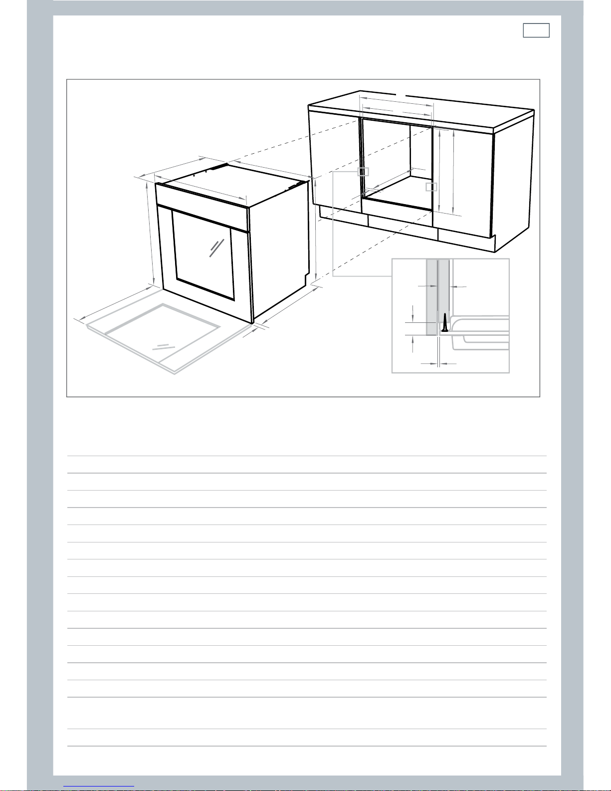
Figure 2 Product and cabinetry dimensions
Installation instructions
Product and cabinetry dimensions (mm)
A overall height* of product 597
B overall width of product 595
C overall depth of product
(excluding handle and knobs) 567
D height of chassis 582
E width of chassis 556
F depth of chassis 545
G depth of oven frame and control panel
(excl. knobs) 22
H depth of oven door
(open) (measured from front of oven frame) 445
I minimum inside width of cavity 560
I
I
overall width of cavity 600
J inside height of cavity 585
J
I
overall height of cavity 600
K minimum inside depth of cavity 550
L flush fitting cabinetry clearance 22
Note: If installing a cooktop above the oven ensure adequate clearance is provided for the
cooktop as per the cooktop manufacturer’s instructions.
*All height measurements include mounted feet.

6
Important:
Please take extra care not to damage the lower trim of the oven.
The space between the bottom of the door and the lower trim is important for the correct air
circulation into the oven.
Ensure the oven sits on wooden blocks or similar supports when it is removed from the carton as
shown in Fig. 3. This will prevent any damage to the lower trim.
After installation check the lower trim is still undamaged. Open the oven door slowly to its fully
open position ensuring there is adequate clearance between the bottom of the door and the
lower trim.
Should the lower trim become damaged, straighten the trim and ensure the oven door opens
fully without obstruction from the lower trim.
Note: You can remove the feet but ensure that the oven does not sit on the lower trim.
The manufacturer does not accept responsibility for any damage to the oven resulting from
incorrect installation.
OVEN DOOR
LOWER TRIM
AIR FLOW
Figure 3 Correct and incorrect placement of trim
Air circulation
7
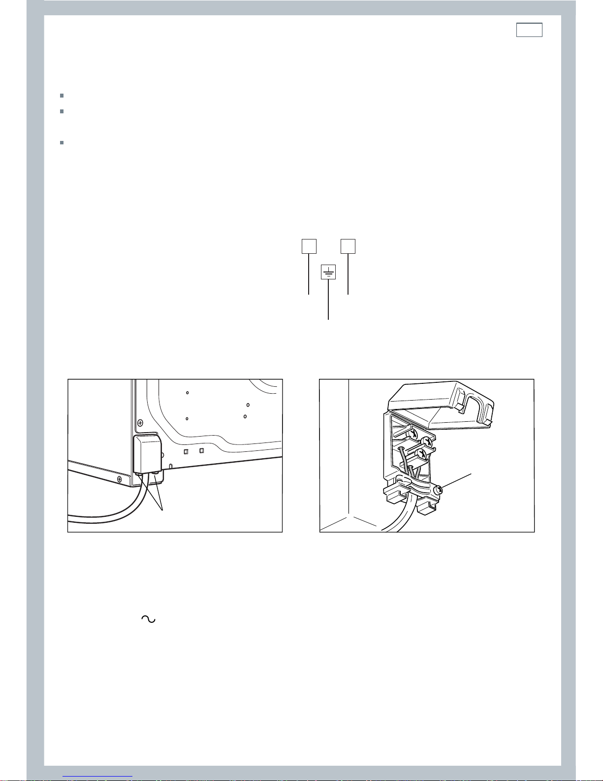
Replacing the power supply cable
Unhook the terminal board cover by inserting a screwdriver into the two hooks “A” (fig. 5).
Open the cable crimp by unscrewing screw “F” (Fig. 6), unscrew the terminal screws and remove
the cable.
Connect the new supply cable, of suitable type and section, to the terminal board following the
diagram in Fig. 4.
230-240 V~ 3095-3370W
230-240 V~ 3600-3830W
E
N
L
1 (L )2
230- 240 V 3 x 1.5 mm
2
A
F
Figure 5 Figure 6
Feeder cable section type HO5RR-F
Figure 4
Electronic
Pyrolytic
8
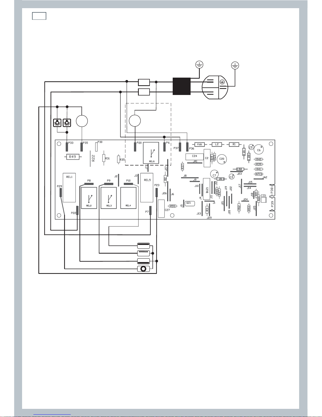
Electronic models
Wiring diagram
Figure 7 Electronic oven wiring diagram
TE
GE
BE
CE
M
N
L
Filter
TL
TL
VT
VR
LF2LF1
T
T
9
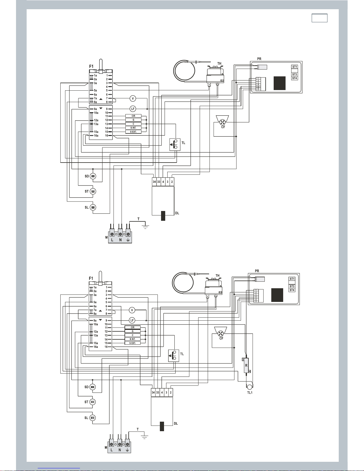
Wiring diagram
Pyrolytic oven NZ AU models
Figure 8a Pyrolytic oven wiring diagram
Figure 8b Pyrolytic oven wiring diagram
Pyrolytic oven GB IE models

10
11
Before using your new oven, please:
1
Read this user guide, taking special note of the ‘Safety and warnings’ section.
2
Remove all accessories and packaging.
3
Set the clock. The oven will not work until the clock has been set.
4
Condition the oven:
Put in the shelves and trays. If you are not using
the sliding shelf supports, then slide in the shelves
and grill pan as shown in Fig 10. Fit them between
the metal runners, with the safety stop notch down
and at the back.
If the shelf supports and catalytic panels are not
already fitted, see ‘Care and cleaning’ for how to do this.
Heat the oven on maximum for:
60 minutes in the
position
30 minutes in the
position
15 minutes in the
position
5
Wipe out the oven with a damp cloth and mild detergent,
and dry thoroughly.
Note: the oven cooling fan comes on automatically at
different stages of the cooking cycle. It blows out warm
air above the door. When the oven is turned off, the
cooling fan may stay on until the oven cools down.
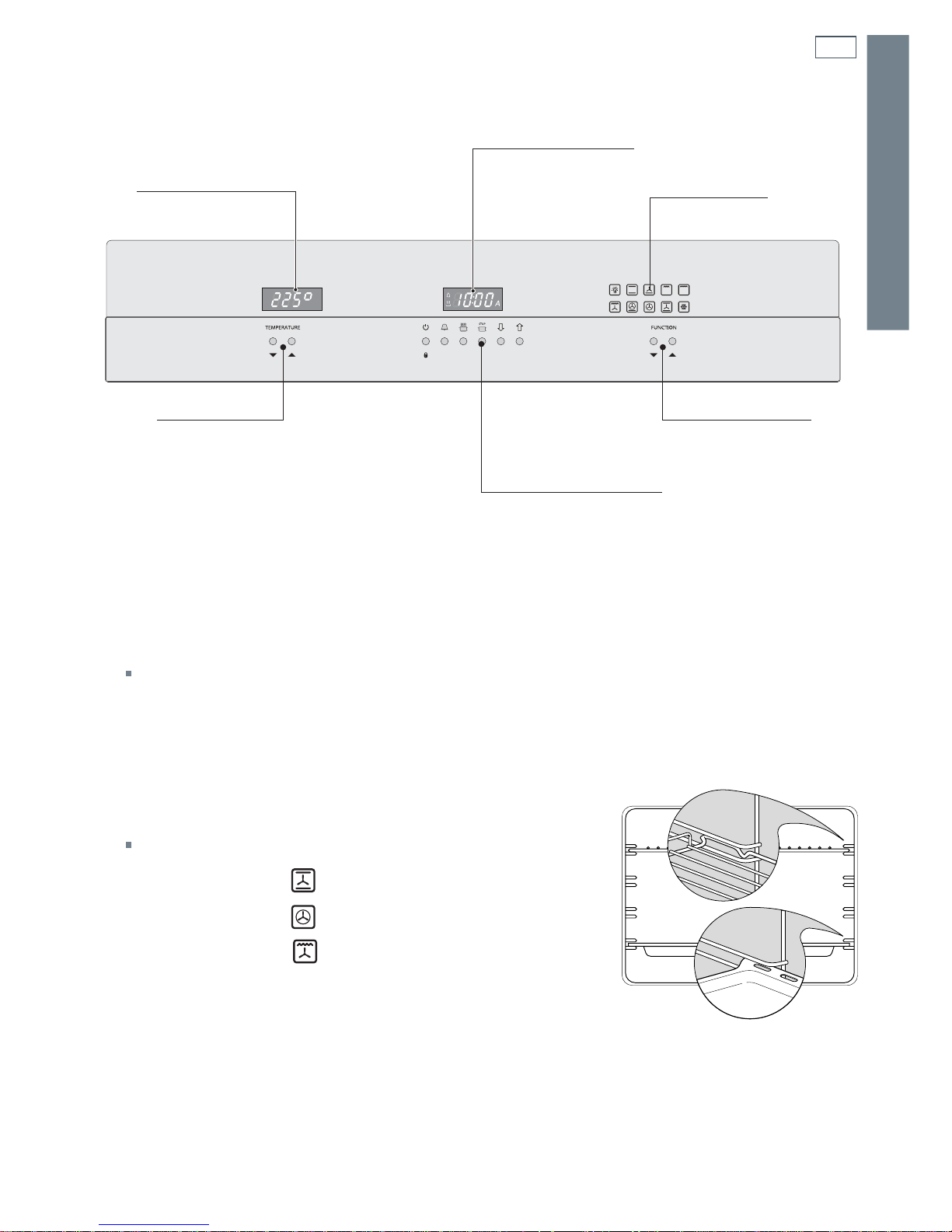
Figure 9 Control panel
Temperature display
Clock display
Functions display
Cooking functions
buttons
Control
buttons
Tem pe ra tu re
buttons
Figure 10 Correct position of shelves and pan
Using your oven for the rst time
ELECTRONIC MODELS
12
ELECTRONIC MODELS
Using the control buttons
Note: After using the control buttons, wait for three beeps to confirm that you can proceed.
To select the volume of the beeps, press the
button.
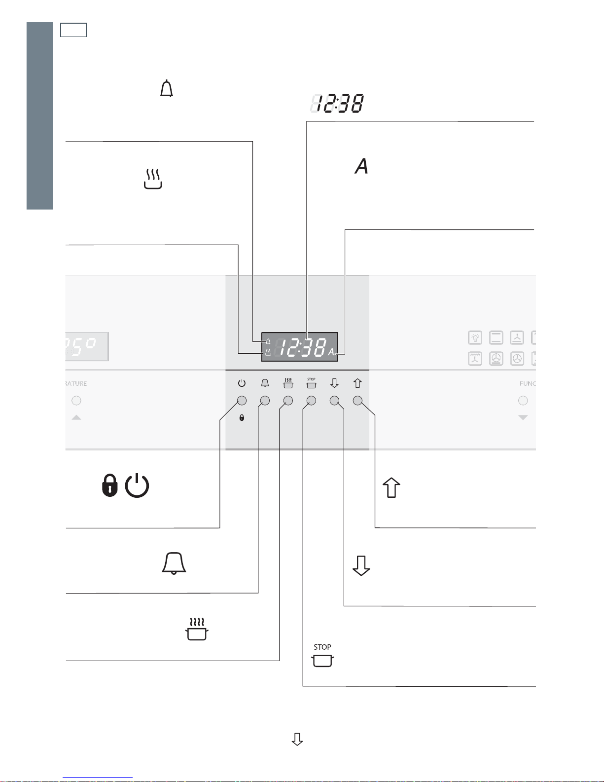
Figure 11 Clock display and control buttons
SYMBOL
Lit = minute minder in operation
Flashing = countdown completed
by the minute minder
SYMBOL
Lit = operation of heating
elements (cooking functions)
Flashing = automatic cooking
completed
DIGITS
Normally time of the day
SYMBOL
Lit = automatic cooking
programmed
Flashing = automatic cooking
completed
BUTTON
ON/OFF or
Childlock selection
BUTTON
Minute minder selection
BUTTON
Cooking time selection
BUTTON
To increase the numbers
on the programmer display
BUTTON
To decrease the numbers
on the programmer display
BUTTON
End cooking time selection
13
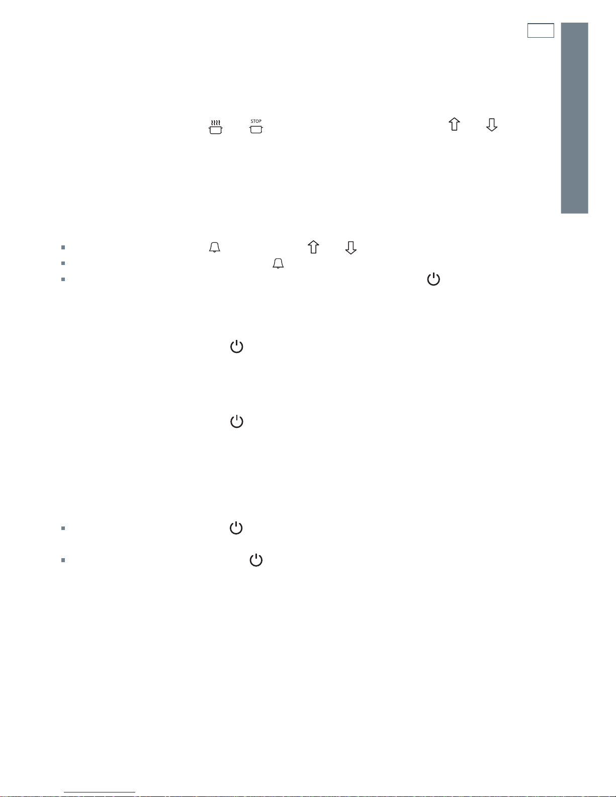
Setting the clock
When first connected, or after a power failure, ‘0:00’ will show on the display.
To set the clock, press the
and buttons together and then press the and buttons.
Note: Changing the time will delete any automatic program.
Using the timer
You can use the timer at any time, even when the oven is not in use. The timer does not turn the
oven off.
The timer can be set for up to 23 hours and 59 minutes.
To set the timer, press the
button, then the and buttons.
To check the remaining time press the
button.
When the time is up, the timer will beep. Press any button (except the
button) to turn it off.
Turning the oven on and off
To turn the oven on, press the button. ‘On’ appears for two seconds on the display, the oven
lamp lights up, and then the time appears on the display. You can now operate your oven.
If you do not use your oven within three minutes, it automatically goes back to stand-by. ‘OFF’
appears for some seconds on the display, the oven lamp goes off, and then the time appears on
the display.
To turn the oven off, press the
button.
Note: do not turn the oven off if you have set it for automatic cooking.
Childlock
In Childlock you can only turn the oven off, use the timer, and check the remaining cooking time
or the end of the cooking time. You can set Childlock during cooking.
To set the Childlock, press the
button for about five seconds. The display shows ‘n--O’, ‘On’ and
then the time appears again.
To release the Childlock, press the
button for about five seconds. The display shows ‘n--O’,
‘OFF’ and then the time appears again.
Using the control buttons
ELECTRONIC MODELS
 Loading...