

Page 1

BUILT-IN OVEN
OB30SP & OB30DP
models
INSTALLATION GUIDE
US CA
Page 2
SAFETY AND WARNINGS
!
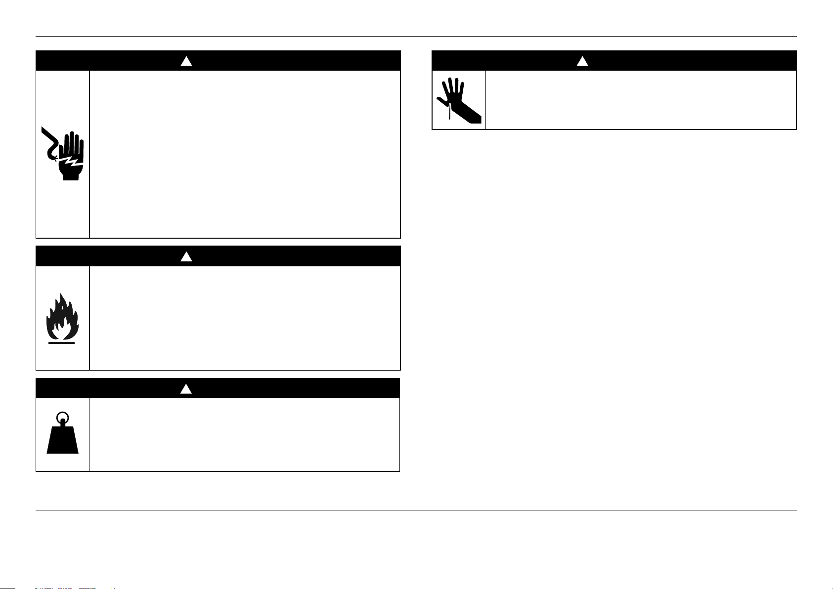
WARNING!
Electric Shock Hazard
Failure to follow this advice may result in
electric shock or death.
• Before carrying out any work on the electrical
section of the appliance, it must be disconnected
from the mains electricity supply.
• Connection to a good earth wiring system is
absolutely essential and mandatory.
• Alterations to the domestic wiring system must
only be made by a qualified electrician.
!
WARNING!
Fire Hazard
Failure to follow this advice may result in
overheating, burning, and injury.
• Do not use adapters, reducers, or branching
devices to connect this appliance to the mains
power supply.
!
WARNING!
Very Heavy
Failure to follow this advice may result in
serious injury.
• Do not attempt to lift this product unassisted.
!
WARNING!
Cut Hazard
Failure to use caution could result in injury.
• Take care – some panel edges are sharp.
WARNING!
To avoid hazard, follow these instructions carefully before installing or using this appliance.
z
Save these instructions for the local inspectors use.
z
Please make this information available to the person installing the appliance — doing so
could reduce your installation costs.
z
This oven is to be installed and connected to the electricity supply only by an
authorized person.
z
If the installation requires alterations to the domestic electrical system, call a qualified
electrician. The electrician should also check that the socket cable section is suitable
forthe electricity drawn by the oven.
z
The oven must be grounded.
z
Installation must comply with your local building and electricity regulations.
z
This appliance must be installed and connected to the mains power supply only by a
suitably qualified person according to these installation instructions and in compliance
with any applicable local building and electricity regulations. Failure to install the
appliance correctly could invalidate any warranty or liability claims.
z
If the power supply cable is damaged, it must be replaced by the manufacturer,
itsservice agent or similarly qualified person in order to avoid a hazard.
z
A circuit breaker is recommended.
z
Do not use adaptors, reducers or branching devices to connect the oven to the mains
electricity supply, as they can cause overheating and burning.
z
Ensure the cavity is completely sealed with no gaps. This is to ensure the oven cooling
system functions correctly.
z
The appliance must not be installed behind a decorative door in order to avoid overheating.
Electrical requirements
z
Connect oven with copper wire only.
z
Do not cut the conduit.
z
A U.L. listed conduit connector must be provided at the junction box.
z
Do not ground to a gas pipe.
z
Do not have a fuse in the grounding or neutral circuit.
z
Fuse both sides of the line.
z
A time delay fuse or circuit breaker is recommended. If using a time delay fuse,
thenfuse both sides of the line.
z
Flexible armored cable from the appliance should be connected directly to the junction box.
z
Connect directly to the fused disconnect (or circuit breaker box) through flexible,
armored or non-metallic sheathed, copper cable (with grounding wire).
z
If codes permit and a separate grounding wire is used, it is recommended that
a qualified electrician determine that the grounding path and wire gauge are in
accordance with local codes.
IMPORTANT!
SAVE THESE INSTRUCTIONS
The models shown in this installation guide may not be available in all markets and are subject to change at any time. For current details about model and specification availability in your country,
please go to our website www.fisherpaykel.com or contact your local Fisher&Paykel dealer.
2
Page 3

PARTS SUPPLIED
Screws
Single oven models (2)
Double oven models (4)
Spacers
Single oven models (2)
Double oven models (4)
Long Trim (1)
To be fitted in
a flush installation.
PRIOR TO INSTALLATION
IMPORTANT!
Some environmental factors and cooking habits can cause condensation in and around the oven during use. To protect surrounding cabinetry from possible damage caused by
frequent or excessive condensation, we recommend moisture-proofing the oven cavity.
z
the countertop and oven cavity are square and level, and are the required dimensions.
z
the installation will comply with all clearance requirements and applicable standards and regulations.
z
the isolating switch will be easily accessible to the customer with the oven installed.
z
the electrician provides sufficient free length of power supply cable to reach from the bottom rear of the cavity to at least 1.5 metres in front of the bottom edge of the opening.
z
the cable may enter the cavity from the side, top or bottom, but top entry must be at the rear of the cavity.
z
the oven connection socket (if fitted) is outside the cavity if the oven is flush to the rear wall.
z
the oven will rest on a surface that can support its weight.
z
the height from the floor suits the customer.
z
you consult local building authorities and by-laws if in doubt regarding installation.
AFTER INSTALLATION
IMPORTANT!
Please take extra care not to damage the lower trim of the oven during installation. The trim is important for correct air circulation and allows the
door to open and close without obstruction. The manufacturer does not accept any responsibility for damage resulting from incorrect installation.
z
the oven door(s) can open fully without obstruction.
z
do not seal the oven into the cabinetry with silicone or glue. This makes future servicing difficult. Fisher&Paykel will not cover the costs of
removing the oven, or of damage caused by this removal.
z
the power supply cable does not touch any hot metal parts.
z
the isolating switch is easily accessible to the customer with the oven installed.
z
you complete the ‘Final checklist’ at the end of the installation.
z
if, after following the instructions given, correct performance cannot be achieved, please contact your nearest Fisher&Paykel Authorized Service
Center, Customer Care, or contact us through our local website listed at the end of this document.
3
Page 4

PRODUCT DIMENSIONS — SINGLE OVENS
A
H
B
G
PRODUCT DIMENSIONS
Ed
F
PROFILEFRONT
OB30S
INCHES MM
A Overall height of product 27 1/8 689
B Overall width of product 29 13/16 757
C Overall depth of product (excl. handle and dials) 23 15/16 608
C
PLAN
4
D Depth of oven front and control panel (excl. handle and dials) 1 9/16 39
E Depth of chassis (does not include oven front) 22 3/8 569
F Height of chassis 26 9/16 675
G Depth of door (open) (measured from front of door) 21 5/8 550
H Overall width of chassis 28 5/16 719
Note: If flush installing, you need to replace the lower trim with the supplied long trim at the base of the
oven, and the depth of the control panel D with the fitted spacer is larger than conventional ovens. Ensure
you have created a 1 5/8" (42mm) recess incabinetry.
Page 5
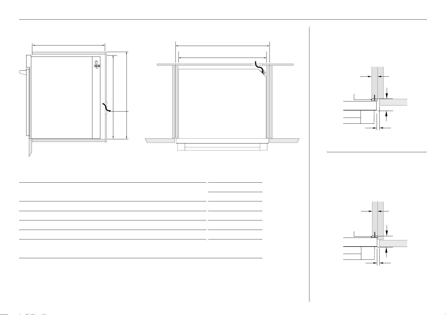
CABINETRY DIMENSIONS — SINGLE OVENS
e b
CABINETRY DIMENSIONS
c d
Electrical
Supply
PROUD INSTALL
a
5/8 – 13/16"
(16-20mm)
spacer
1 – 5/8"
(42mm)
min 1/16"
(2mm)
PLANPROFILE
FLUSH INSTALL
OB30S
INCHES MM
A Minimum inside width of cavity 28 1/2 724
B Overall width of cabinetry 30 1/8 764
C Minimum inside height of cavity 26 13/16 681
D Overall height of cabinetry 27 3/8 693
E Minimum inside depth of cavity
z
Proud install
z
Flush install
22 5/8
24 3/16
575
614
Notes:
If installing a cooktop above the oven, ensure adequate clearance is provided for the cooktop as per the cooktop
manufacturer’sinstructions.
Ensure the cavity is completely sealed with no gaps. This is to ensure the oven cooling system functions correctly.
spacer
5/8 – 13/16"
(16-20mm)
1 – 5/8"
(42mm)
min 1/16"
(2mm)
5
Page 6

PRODUCT DIMENSIONS — DOUBLE OVENS
A
B
ED
F
G
h
i
PRODUCT DIMENSIONS
A Overall height of product 48 1/2 1232
B Overall width of product 29 13/16 757
C Overall depth of product (excl. handle and dials) 23 15/16 608
D Depth of oven front and control panel (excl. handle and dials) 1 9/16 39
C
PLAN
6
E Depth of chassis (does not include oven front) 22 7/16 569
F Height of chassis 47 15/16 1218
G Depth of upper door (open) (measured from front of door) 21 5/8 550
H Depth of lower door (open) (measured from front of door) 20 7/8 530
I Overall width of chassis 28 5/16 719
Note: If flush installing, you need to replace the lower trim with the supplied long trim at the base of the
oven, and the depth of the control panel D with the fitted spacer is larger than conventional ovens. Ensure
you have created a 1 5/8" (42mm) recess incabinetry.
PROFILEFRONT
OB30D
INCHES MM
Page 7

e
c d
Electrical
Supply
CABINETRY DIMENSIONS — DOUBLE OVENS
b
a
PROUD INSTALL
5/8 – 13/16"
(16-20mm)
spacer
1 – 5/8"
(42mm)
min 1/16"
(2mm)
PROFILE PLAN
CABINETRY DIMENSIONS
INCHES MM
OB30D
A Minimum inside width of cavity 28 1/2 724
B Overall width of cabinetry 30 762
C Minimum inside height of cavity 48 3/16 1224
D Overall height of cabinetry 48 11/16 1236
E Minimum inside depth of cavity
z
Proud install
z
Flush install
22 5/8
24 3/16
575
614
Notes:
If installing a cooktop above the oven, ensure adequate clearance is provided for the cooktop as per the cooktop
manufacturer’sinstructions.
Ensure the cavity is completely sealed with no gaps. This is to ensure the oven cooling system functions correctly.
FLUSH INSTALL
spacer
5/8 – 13/16"
(16-20mm)
1 – 5/8"
(42mm)
min 1/16"
(2mm)
7
Page 8

Single model shown for illustration purposes only
IMPORTANT!
z
When you remove the oven from the carton
be careful not to damage the lower trim.
Thetrimisimportant for both ventilation and to
ensure the door opens fully without obstruction.
z
Ensure you remove the Long Trim
from thepackaging.
UNPACKING THE OVEN
Lower trim
Remove the accessories box from
the top of the oven and set aside.
Recycle responsibly.
8
Page 9

REMOVING AND REFITTING THE DOOR(S)
IMPORTANT!
z
Take care, the oven door is heavy.
z
Do not lift the oven door by its handle. Doing so may damage the door.
z
Ensure the oven and the door are cool before you begin to remove the door.
z
Before removing the door, ensure there is a large enough clear, protected surface in the kitchen to rest the door on.
To remove the door(s)
1
2
3
Open the door completely.
Open the hinge locks fully
on both sides
Holding the door on both
sides, lift door back up to 45°
and carefully pull the door out
and away from the hinges.
To refit the door(s)
1
2
3
Holding the door at 45°, carefully
align the hinge tongues with the
hinge slots. Push the door in until
you feel the latches locate into
position on each side.
Open the door completely and
ensure both hinges are secured
by the correct notches.
Rotate the locks up into the
closed position ensuring they rest
inside the slots completely. Note:
Incorrect installation will prevent
door from correctly sealing.
4
Close the oven door ensuring that
when closed, the door is vertical and
parallel to any surrounding cabinetry
9
Page 10
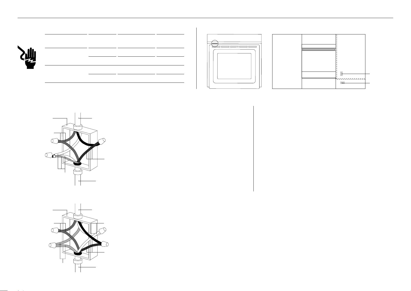
ELECTRICAL CONNECTION TO JUNCTION BOX
MODEL VOLTAGE
OB30 Single 208 V 16.6 A 3.5 kW
OB30 Double 208 V 33.2 A 7.0 kW
Connection methods
box
red
wires
a
white and
green grounding
oven wires –
factory taped
MAX CURRENT
DRAW
MAX LOAD
240 V 19.4 A 4.6 kW
240 V 38.3 A 9.2 kW
If local codes permit connecting the cabinet-grounding
cable from
power supply
conductor to the neutral (white) wire in the junction box:
1 Disconnect the power supply.
2 Remove the junction box cover.
3 Connect the oven cable to the junction box through
the U.L. listed conduitconnector.
4 Connect the two black wires together with
twist-on connectors.
5 Connect the two red wires together with twist-on
black
wires
connectors.
6 Connect electrical connection according to local
codes andordinances.
7 Connect the factory-taped green and white oven cable
U.L.-listed
conduit
connector
wires to the neutral (white) wire in the junction box.
8 Replace the junction box cover.
Nameplate location
Junction box locations
junction box
location for
undercounter
installation
junction box
location for
wall installation
If local codes DO NOT PERMIT connecting the cabinet-grounding
conductor to the neutral (white) wire in junction box:
1 Disconnect the power supply.
2 Remove the junction box cover.
3 Connect the oven cable to the junction box through the U.L.-
listed conduit connector.
4 Connect the two black wires together with twist-on connectors.
5 Connect the two red wires together with twist-on connectors.
6 Connect electrical connection according to local codes and
ordinances.
7 Separate the factory-taped green andwhite oven cable wires.
8 Connect the white oven cable wire to the neutral (white) wire
in junction box.
9 Connect the green grounding oven cable wire to a grounded
wire in the junctionbox.
!0 Replace the junction box cover.
B
10
box
red
wires
green grounding
oven wires –
factory taped
cable from
power supply
white
wires
black
wires
U.L.-listed
conduit
connector
Four-wire electrical system
1 Disconnect the power supply.
2 Remove the junction box cover.
3 Connect the oven cable to the junction box through the U.L.-listed conduit connector.
4 Connect the two black wires together with twist-on connectors.
5 Connect the two red wires together with twist-on connectors.
6 Connect electrical connection according to local codes and ordinances.
7 Separate the green and white oven cablewires.
8 Connect the white oven cable wire to theneutral (white) wire in junction box.
9 Connect the green grounding oven cable wire to the (green) grounding wire in thejunction box.
Do not connect the green grounding wire to the neutral (white) wire in junction box.
!0 Replace the junction box cover.
Page 11

spacer
SECURE THE OVEN TO THE CABINETRY
IMPORTANT!
z
Do not lift the oven by the door handle.
z
Do not over-tighten the screws.
z
Do not seal the oven into the cabinetry with silicone or glue.
This makes future servicing difficult. Fisher & Paykel will not
cover the costs of removing the oven, or of damage caused
by this removal.
1 Position the oven in the prepared cavity.
2 Open the oven door fully.
3 Mark and pre-drill the screw holes.
4 Use the supplied screws to secure the oven to the cabinetry.
Ensure supplied spacer is fitted between oven and cabinetry.
11
Page 12

FLUSH INSTALLATION ONLY — REPLACE THE LOWER TRIM WITH THE SUPPLIED LONG TRIM
Unscrew and remove
the installed lower trim
12
Replace with the
supplied long trim
Page 13

FINAL CHECKLIST
TO BE COMPLETED BY THE INSTALLER
Ensure the oven is level and securely fitted to the cabinetry.
Check the lower trim is undamaged.
Open the oven door slowly until it is fully open and check there is
adequate clearance between the bottom of the door and the lower trim.
This is to ensure correct air circulation. Should the lower trim become damaged,
straighten the trim and ensure the oven door opens fully without obstruction.
Ensure you remove all internal packaging (including the circular yellow packing
retainers holding the accessory box in place).
Ensure all oven vents and openings are clear and free of any obstruction or damage.
IMPORTANT!
Failure to ensure all oven vents are clear may result in poor product performance.
Ensure the isolating switch is accessible by the customer.
TEST OPERATION:
Turn the power to the oven on. The display should light up.
Set the clock following the instructions in the ‘User guide’.
Set the oven to Bake at 120°F (50oC). The light should come on inside the oven cavity
and air should blow out of the vent at the top of the oven. After five minutes, open
the oven door: the air inside should feel warm. Turn the oven off.
Have you demonstrated the basic operation to the customer?
Complete and keep for safe reference:
Model
Serial No.
Purchase Date
Purchaser
Dealer Address
Installer’s Name
Installer’s Signature
Installation Company
Installation Date
13
Page 14

FISHERPAYKEL.COM
The product specifications in this document apply to the specific products
and models described at the date of issue. Under our policy of continuous
product improvement, these specifications may change at any time. You should
therefore check with your Dealer to ensure this booklet correctly describes the
© Fisher & Paykel Appliances 2019. All rights reserved.
product currently available.
US CA
592096A 10.19
 Loading...