

Fisher & Paykel Intuitive DEIX2, Intuitive DGIX2, DE27CW1 Installation Instructions And User Manual
Page 1
DEIX2, DGIX2
Secadora de ropa Intuitive™
Instructivo de instalación
y guía del usuario US CA (ES)
Installation instructions
and user guide
US CA (EN)
Intuitive™ clothes dryer
Page 2

2
The Governor of California is required to publish a list of substances known to the
state of California to cause cancer or reproductive harm and requires business to
warn customers of potential exposures to such substances.
Gas appliances contain or produce substances, which can cause death, or serious
illness and which are known to the State of California to cause cancer, birth defects,
or other reproductive harm. To reduce the risk from substances in fuel or from
fuel combustion, make sure this appliance is installed, operated, and maintained
according to the manufacturers instructions.
English Page 2 – 56
Español Pág 57 – 110
WARNING: For your safety the
information in this manual must be
followed to minimize the risk of fire or
explosion or to prevent property
damage, personal injury or death.
—Do not store or use gasoline or other
flammable vapors and liquids in the
vicinity of this or any other appliance.
—WHAT TO DO IF YOU SMELL GAS
• Do not try to light any appliance.
• Do not touch any electrical switch; do
not use any phone in your building.
• Clear the room, building or area of all
occupants.
• Immediately call y our gas supplier from
a neighbor’s phone. Follow the gas
supplier’s instructions.
• If you cannot reach your gas supplier,
call the fire department.
—Installation and service must be
performed by a qualified installer, service
agency or the gas supplier.
Page 3

3
Contents
Dryer Safety
5
Important Safety Instructions
6
Warranty 8
Installation Instructions
9
Installer Responsibilities, Location Requirements 10
Dimensions 12
Mobile Home Installation 13
Exhausting 14
Alternative Installation for Close Clearances 18
Exhaust Venting 19
Installation 20
Grounding Instructions 22
Electrical Requirements 23
Gas Requirements 29
Level Machine, Final Installation Checklist 32
Features
33
Operating Instructions
34
Fabric Type
Heavy, Mixed, Casual, Dry and Wear 37
Light, Air Dry 38
How Dry?
Autosensing, Dryness Levels 39
Display Screen
40
All About the Options Button
40
Progress Screen
41
The Options
Wrinkle Free, Time Dry 42
End of Cycle Beeps, Reminders, Cycle Tips, Troubleshooting 43
Lifecycles™
Family Allergy, Towels, Shirts, Lingerie 44
Special Freshen Up, Warm Up, Dry Clean 44
Bulky Blankets, Jeans, Comforter 45
Using Your Dryer
Sorting, Loading 46
Lint Bucket 47
Lidlock
Power failure 48
Care Labels
49
Cleaning
50
If your Intuitive™ Dryer Beeps for Help
51
Trouble Shooting
52
Limited Warranty
54
US
CA
Page 4
4
Thank you for buying a Fisher & Paykel Intuitive™ dryer.
We hope you enjoy using the Intuitive™ dryer as much as we have enjoyed designing it. We’ve
developed this dryer to treat your clothes with the utmost care, drying them gently so they
will look better for longer. We know you’ll enjoy the benefits of its easy loading drum, reverse
tumbling and lint removal system.
Please take the time to read this User Guide carefully. It will help you to operate and maintain
your new Intuitive™ dryer.
Your safety, and the safety of others is very important. Located on your dryer and throughout this
guide are safety messages and instructions; it is important that you understand and follow them.
Page 5
5
Dryer Safety
Symbols
Symbols will be used in this Guide to highlight when extra care is required. Abide by these at
all times to ensure you and your family are not harmed while operating your dryer.
It is important to always act with caution and use common sense when operating your dryer.
Use only as per instructed by the User Guide.
DANGER
This is the safety alert symbol. This symbol alerts you to hazards that can kill
or hurt you and others.
The safety alert symbol and the word DANGER or WARNING will precede all
safety messages. These words mean:
You can be killed or seriously injured if you don’t
immediately follow instructions.
You can be killed or seriously injured if you don’t
follow instructions.
All safety messages will identify the hazard, tell you how to reduce the chance of injury,
and tell you what can happen if the instructions are not followed.
WARNING
US
CA
Page 6
6
Important Safety Instructions
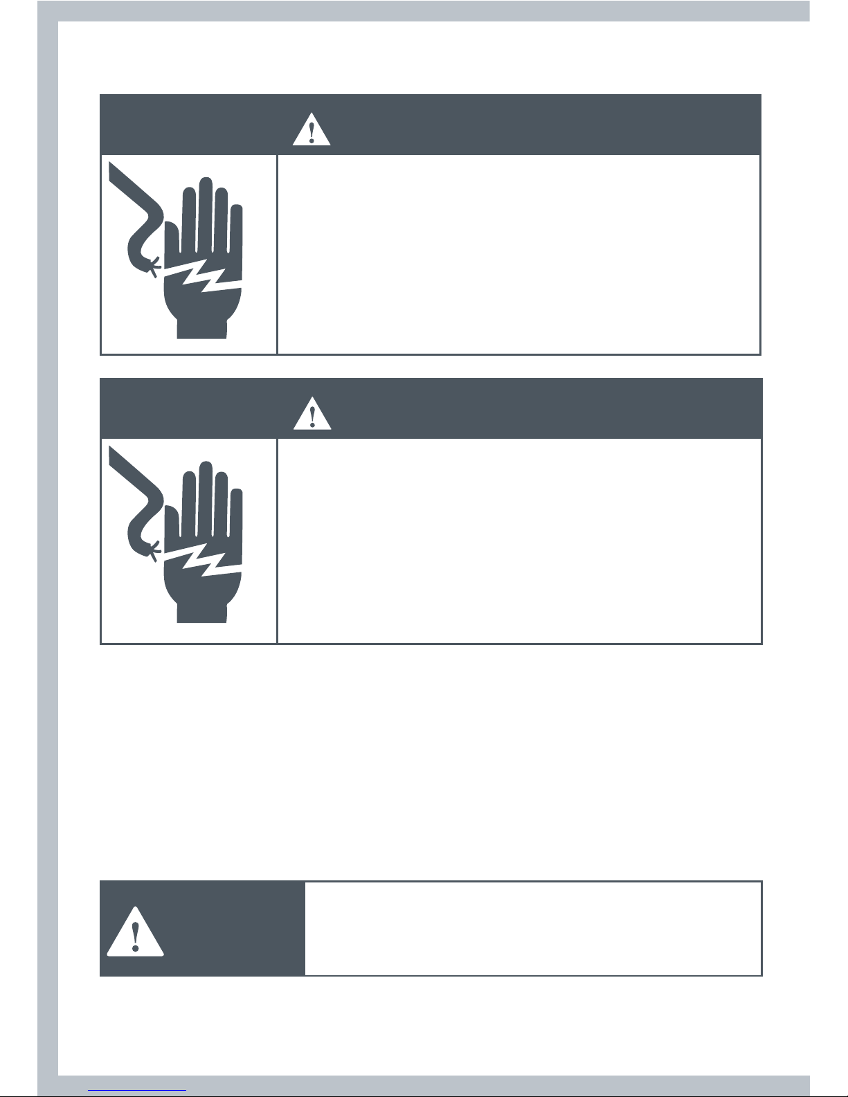
WARNING
Electric Shock Hazard
Follow the safety precautions outlined in this User Guide.
Failure to do so can result in death or electric shock.
Safety Precautions
Read all instructions carefully before using this dryer.
Use this dryer only for its intended purpose as described in this User Guide.
To minimize the possibility of electric shock, unplug this dryer from the power supply or
disconnect the dryer at the household distribution panel (by removing the fuse or switching
off the circuit breaker) before attempting any user maintenance or cleaning.
Installations must be performed by a qualified or licensed contractor, plumber or gasfitter
qualified or licensed by the state, province, or region where this appliance is being installed.
This dryer must be properly installed and located in accordance with the Installation Instructions
before it is used.
This dryer must be properly grounded to conform with all governing codes and ordinances.
Follow details in Installation Instructions.
Do not install or store the dryer where it will be exposed to water or exposed to the weather.
Connect to a properly protected, rated and sized power supply circuit to avoid electrical overload.
Do not repair or replace any part of the appliance or attempt any servicing, unless specifically
recommended in the published user repair instructions that you understand and have the skills
to carry out.
When disconnecting the dryer, pull by the plug rather than the cord or junction of the cord plug,
to avoid damage to the cord or junction of the cord plug.
Make sure the cord is located so that it will not be stepped on, tripped over or otherwise subject
to stress or damage.
Do not tamper with the controls or the lid lock.
Note: Pressing the POWER button does NOT disconnect the dryer from the power supply, even
though the lights are out.
Do not operate this dryer if it is damaged, malfunctioning, partially disassembled or has missing
or broken parts, including a damaged cord or plug.
This dryer must be directly connected to an approved fixed electrical outlet. It cannot be
plugged into an extension cord.
Page 7

7
Important Safety Instructions
WARNING
Fire Hazard
Only dry fabrics that have been washed with water.
Do not use heat to dry articles containing foam rubber or
similarly textured rubber-like materials. Dry on the Air Dry cycle.
A clothes dryer produces combustible lint and must be
exhausted outdoors. Take care to prevent the accumulation of
lint around the exhaust opening and in the surrounding area.
Do not use fabric softeners or products to eliminate static
unless recommended by the manufacturer of the fabric softener
or product.
Failure to follow these instructions can result in death or
personal injury.
To Reduce the Risk of Fire in a Tumble Dryer the Following Should
be Observed:
Do not place items in a tumble dryer that have previously been cleaned in, washed in, soaked
in, or spot cleaned with flammable liquids or solids. They are a fire or explosion hazard. Highly
flammable substances commonly used in domestic environments include acetone, denatured
alcohol, gasoline, kerosene, some brands of spot removers and dry cleaning solvents, turpentine,
waxes, wax removers, vegetable oil, fish oil, massage oil, and cooking oil.
Do not leave hot oil-affected items in a pile or stack. This can prevent heat from escaping and
can create a fire hazard. Oil-affected items can ignite spontaneously, especially when exposed to
heat sources such as a tumble dryer. The items become warm causing an oxidation reaction in
the oil. This oxidation creates heat. If the heat cannot escape the items can become hot enough
to catch fire.
Do not use heat to dry items containing rubber, foam rubber, plastic or similar materials, (such as
padded bras, bath mats, rugs, bibs, baby pants, plastic bags, pillows etc), as these materials might
melt or burn. Some rubber materials when heated can under certain circumstances produce fire
by spontaneous combustion. Dry only on the AIR DRY cycle.
Unless specifically recommended by their manufacturer, do not use fabric softeners or similar
products in a tumble dryer.
Do not store or use gasoline or other flammable gases and liquids near this or any other appliance.
Keep the area around and underneath your dryer free from the accumulation of combustible
materials such as lint, paper, rags, chemicals etc.
Do not store any items that may burn or melt (such as paper materials, plastics or plastic
containers etc) next to the dryer.
Empty the lint bucket before the lint reaches the top of the transparent section. (usually once
a week).
US
CA
Page 8

8
Important Safety Instructions/Warranty
The dryer must be exhausted to the outside. Carefully follow the venting details in the
Installation Instructions.
Keep the floor around your dryer clean and dry to reduce the possibility of slipping.
If your dryer is running and you want to unload or add clothes, press START/PAUSE and wait
until the machine has unlocked the lid. Do not force it open.
Do not reach into the appliance if the drum is moving.
Close supervision is necessary if this dryer is used by or near children. Do not allow children to
play inside, around or with this dryer or any other appliance.
Never climb on, climb into, or stand on the dryer top, lid or drum.
Undergarments that contain metal reinforcements should not be placed directly in the dryer.
Damage to the dryer can result if the metal reinforcements come loose during drying.
The interior of the appliance and exhaust duct should be cleaned periodically by qualified
service personnel.
Before the appliance is removed from service or discarded remove the lid and the drum door to
the drying compartment.
SAVE THESE INSTRUCTIONS
Warranty
Your dryer has been made to the highest standards. Years of development and rigorous testing
ensure that you have bought a world-class product, in the unlikely event that a problem should
occur, refer to the Warranty section at the back of this Guide (refer to page 54).
If you have a problem with your dryer refer to our troubleshooting section. If your problem
is not referenced, please always contact your Fisher & Paykel Authorized Service Agent or our
Customer Care Center (Toll Free 1 888 9 FNP USA (1 888 9 367 872)) rather than attempting to fix
it yourself.
Page 9
9
Installation Instructions
Read the Important Safety Instructions on pages 6 – 8 before you start
installing the dryer.
Check to make sure you have all the tools and parts necessary to correctly install this appliance.
Tools Required
¼’’ nut driver or socket wrench
Phillips screwdriver
Flat-blade screwdriver
Adjustable wrench 8” or 10” (20cm or 25cm) for gas connections
Pipe joint compound (pipe dope or tape) for gas pipe connections that is resistant to LP Propane,
Butane and Natural Gas (Gas models only)
Level
Caulking gun and compound (for installing new exhaust vent)
Gloves
Safety glasses
Knife
Duct tape
Parts Supplied
2 feet inserts for front feet.
A power supply cord is supplied already connected to the gas dryer (Gas models only)
Check to make sure all parts have been supplied.
Accessories
Mobile Home Installation Kit Part No 395488
Natural Gas to LP Conversion Kit Part No 395489 (Gas models only)
LP to Natural Gas Conversion Kit Part No 395490 (Gas models only)
Kit Element 208V Part No 395500 (Electric models only)
Parts Needed
Check with local codes and read electrical, gas and venting requirements before purchasing parts.
US
CA
Page 10
To the Installer
The correct installation of the dryer is your responsibility.
Be sure you read the following instructions carefully before you start to install the dryer. These
instructions should be left with the home owner for future reference.
It is Your Responsibility to:
Observe all governing codes and ordinances.
Check code requirements. Some codes limit or do not permit installation of clothes dryers in
garages, closets, mobile homes or sleeping quarters. Contact your local building inspector.
Adhere to these installation instructions.
Allow for spacing requirements with side by side installations (refer page 11).
Make sure you have all items necessary for correct installation.
Properly install the dryer.
Contact a qualified installer to ensure that the electrical and gas installation meets all national
and local codes and ordinances. (See page 6).
Location Requirements
WARNING
Explosion Hazard
Keep flammable materials and vapors, such as gasoline, away
from the dryer.
Place dryer at least 18 inches (46 cm) above the floor for a
garage installation.
Failure to do so can result in death, explosion, fire, or burns.
The dryer must be installed or stored in an area which is not exposed to water or weather.
It is extremely important that the dryer is installed in a well ventilated location. This dryer must
exhaust air outdoors. Do not install the dryer in any room or closet which does not permit the
free flow of replacement air.
The free area of any opening for the introduction of outside air shall not be less than twice the
area of the dryer exhaust outlet.
Before installing the dryer ensure that there is sufficient height to fully open the lid. Allow
sufficient room behind the dryer for the exhaust. The air intake is at the rear of the dryer. Ensure
that there is a sufficient air passage on each side of the dryer for intake air.
10
Page 11
Location Requirements
The area in which the dryer is located must be
kept clear and free from combustible materials,
gasoline and other flammable vapors and liquids.
A dryer produces combustible lint so the area
around the dryer must be cleaned regularly to
keep it free of lint.
This dryer can only be vented from the rear and
must be exhausted to the outdoors.
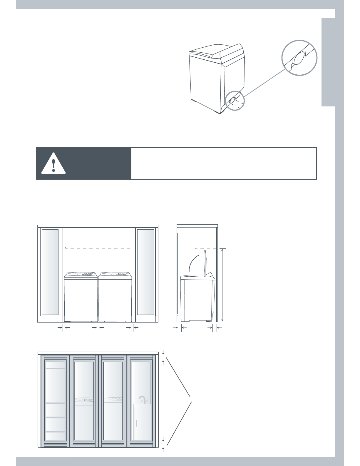
Alcove or Closet Installation
WARNING
When installing a dryer in a closet/alcove it must be
exhausted to the outdoors. No other fuel burning
appliance can be installed in the same closet or alcove.
The top opening area in the door must be a minimum of 48 square inches (310cm
2
) and the
bottom opening area must have a minimum of 24 square inches (155cm
2
). These openings must
never be obstructed (a louvred door with the minimum air opening is acceptable). Minimum
installation clearances are required but more clearance is recommended.
1” (25mm) 1” (25mm) 1” (25mm)
min 2” (50mm) min 3” (76mm)
min 56 /”
(1430mm)
48 sq” (310cm
2
)
total ventation area
72 sq” (465cm
2
)
24 sq” (155cm2)
11
US
CA
Page 12
12
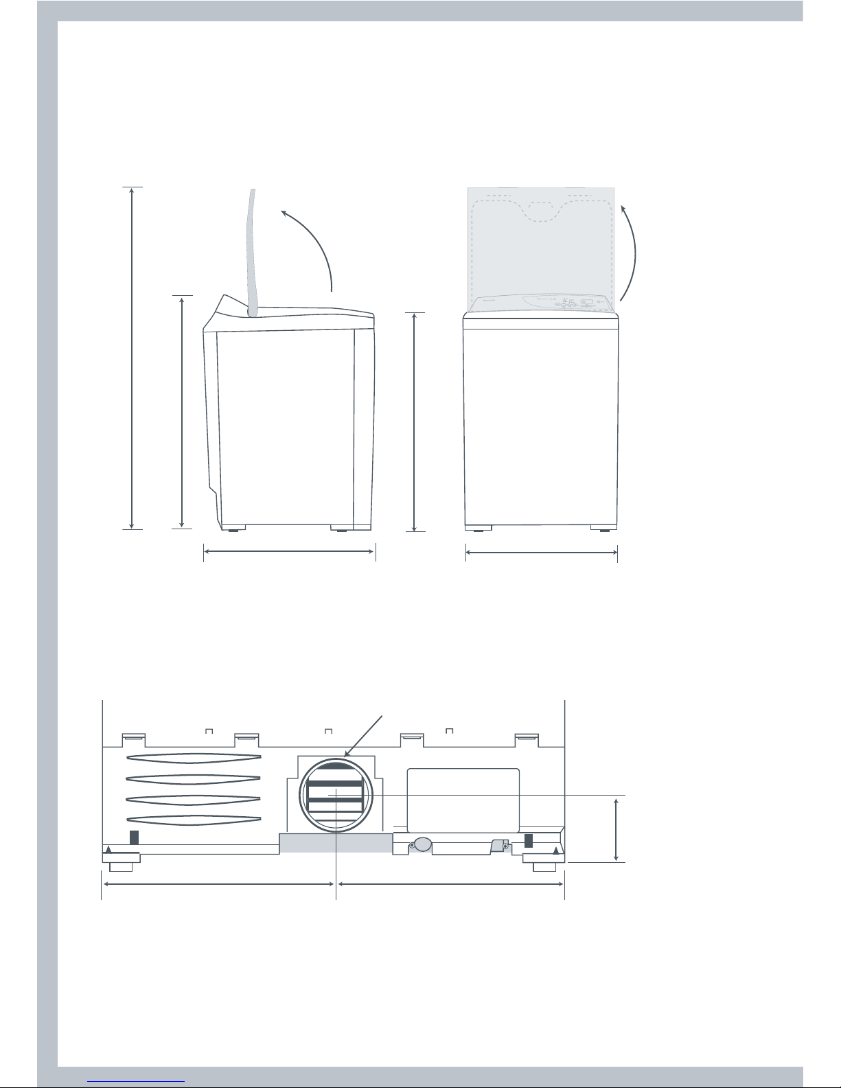
Dimensions
Lid Clearance
Check that there is enough clearance for the lid to fully open.
56” (1422mm)
39 /” – 41 ⁄”
(1010 – 1050mm)
27 ⁄” (700mm)
37” – 37 ⁄”
(925 – 955mm)
27” (685mm)
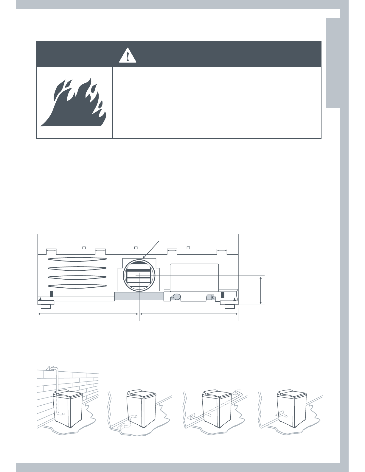
Exhaust Outlet Location
Exhaust outlet
Does not include
foot height
13 ⁄” (333mm)
13 ⁄” (352mm)
4 ⁄”
(111mm)
Page 13
13
Dimensions
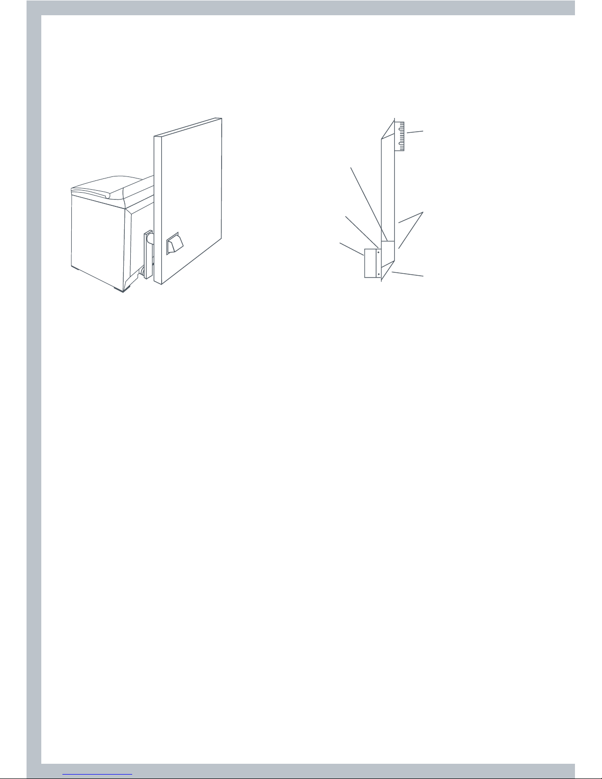
Mobile Home Installation
The installation of the dryer in a mobile home must conform to the Manufactured Home
Construction and Safety Standard Title 24 CFR, Part 3280 {formerly the Federal Standard for
Mobile Home Construction and Safety, Title 24 HUD (Part 280), 1975} for the United States or
Standard CAN/CSA – Z240MH for Canada.
When installing a dryer in a mobile home, provisions for anchoring the dryer to the floor must
be made.
A Mobile Home anchoring installation kit is available with instructions (see Accessories
page 9). Locate in an area that has adequate outside make up air (a minimum of 72 square
inches of unobstructed opening is required).
Mobile home installations must be exhausted to the outdoors with the exhaust duct
termination securely fastened to the mobile home structure, using materials that will not
support combustion.
The exhaust duct must not terminate beneath the mobile home. See the section on exhausting
for more information.
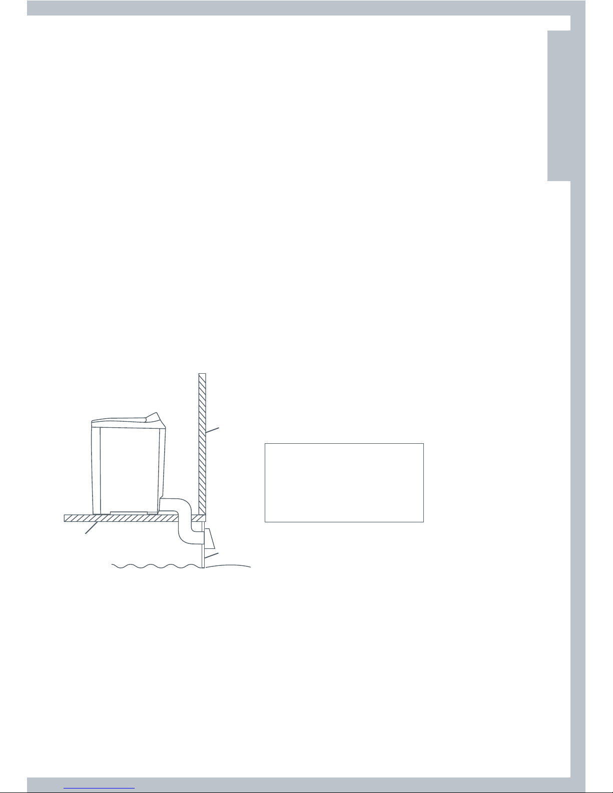
outside
wall
The dryer must be
exhausted outside
floor
enclosed area
skirting
The exhaust vent must be securely
fastened to a non-combustible
portion of the mobile home
structure and must not terminate
beneath the mobile home.
US
CA
Page 14
14
Exhausting
WARNING
Fire Hazard
The dryer must be vented to the outdoors.
Use rigid or thick wall flexible metal exhaust duct.
Do not use a plastic exhaust duct.
Do not use a metal foil exhaust duct.
Failure to follow these instructions can result in death or fire.
The dryer must be exhausted to the outdoors. This will prevent the build up of lint and moisture
in the room in which it is located and reduce the risk of fire.
This appliance must always be vented to the outdoors.
Exhaust ducting products can be purchased from your local Appliance store or Hardware store.
Plastic or metal foil flexible duct can kink, sag, be punctured, reduce airflow, extend drying times
and affect dryer operation.
A minimum of 4 inch (100mm) thick wall flexible metal or rigid galvanised metal duct must be
used. Using ducts larger than 4 inches (100mm) diameter may result in more lint accumulating.
Using straight rigid metal ducting will minimize lint accumulation. Thick wall flexible metal
ducting may be used but care must be exercised to avoid sharp bends which may squash the
duct and cause blockages. Do not use plastic ducting or thin wall flexible metal ducting.
Use duct tape to secure joints. Do not use screws as they collect lint.
Keep ducting as short and straight as possible. Do not exceed the maximum exhaust duct
lengths stated later in these installation instructions.
Do not exhaust the dryer into any other duct, chimney or gas vent, a wall, a ceiling or any
concealed space in a building. Do not exhaust the dryer under a house or mobile home or a
porch, or into a window well or other area that will accumulate lint.
The exhaust duct should end with an exhaust hood with a
swing out damper to prevent back drafts and entry of wild life.
Never use exhaust hoods with a magnetic damper. The hood
should have at least 12 inches (305mm) clearance between the
bottom of the hood and the ground or other obstruction. The
hood opening should point down. Never install a screen over
the exhaust outlet.
12” (305mm)
Page 15
15
Exhausting
To reduce condensation, insulate any ducting which passes through unheated areas.
Slope the duct gently downwards to the hood, to drain condensation and reduce lint build up.
Avoid sag or loops in the duct as they may collect and store water and accumulate lint.
Before using an existing exhaust duct system for a dryer ensure that:
No plastic or other potentially combustible duct or flexible metal foil ducting has been used.
The duct is not pierced, kinked or crushed.
The duct does not exceed the maximum recommended length for the new dryer.
The exhaust hood damper opens and closes freely and with sufficient movement.
Static pressure in the exhaust ducting does not exceed 1 inch (250Pa), or is not less than 0 inches
of water column (ie. negative pressure), when measured with a manometer in the first 6 inches
of the duct, with the dryer running on Air Dry (no heat) setting.
The exhaust duct system meets all relevant local, state and national codes.
All ducting should be inspected and cleaned at least once a year to remove accumulated lint.
Frequently check that the damper on the exhaust hood moves sufficiently and opens and
shuts freely.
Mobile Home Installations
A Mobile Home Installation Kit is available (see Accessories page 9 and notes page 13).
Determine Vent Duct Length
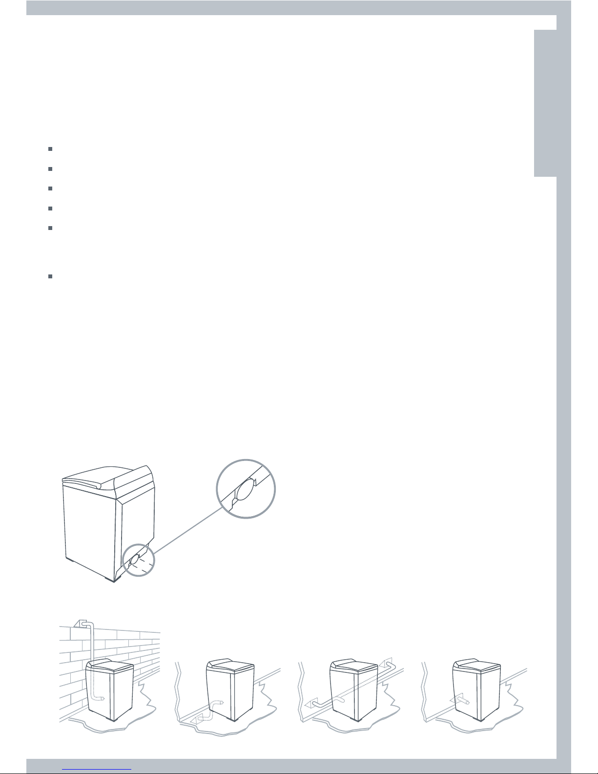
This dryer can only be vented from the rear and must be exhausted to the outdoors.
Different types of vent arrangements are shown below.
US
CA
Page 16

16
Exhausting
Choose a route that will provide the straightest and most direct path outdoors. Plan the
installation to use the fewest number of elbows and turns.
When using elbows (rigid duct) or making turns (thick wall flexible metal duct), allow as much
room as possible. With thick wall flexible metal duct bend duct gradually to avoid kinking and
avoid 90˚ turns.
recommended acceptable
Maximum Length of Exhaust Duct
The maximum length of the exhaust duct system depends upon:
The type of ducts (rigid or thick walled flexible metal).
The number of elbows or bends used.
1
Refer to the exhaust duct length chart that matches your hood type for the maximum duct
lengths you can use. Do not use duct runs longer than specified in the exhaust duct length
charts (refer to next page).
Exhaust duct systems longer than specified will:
Accumulate lint creating a potential fire hazard.
Shorten the life of the dryer.
Reduce performance, resulting in longer drying times and an increased energy usage.
2
Determine the number of elbows/bends you will need.
3
In the column listing the type of metal duct you are using (rigid or thick wall flexible metal), find
the maximum length of metal duct on the same line as the number of elbows/bends to be used
(refer to next page).
Page 17
17
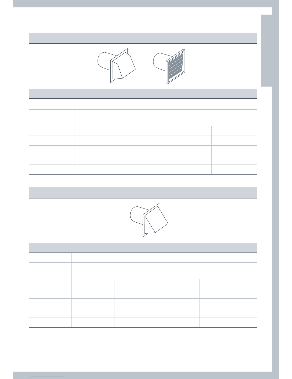
Preferred 4” Hoods
When you have a 4” (10cm) Hood
Maximum length of 4” diameter metal duct.
Number of 90˚
elbows/bends
Rigid
Thick Wall Flexible Metal
(fully extended)
0 64ft 19.5m 36ft 10.9m
1 54ft 16.5m 31ft 9.4m
2 44ft 13.4m 27ft 8.2m
3 35ft 10.6m 25ft 7.6m
4 27ft 8.2m 23ft 7.0m
Acceptable 2 ½”Hood
When you have a 2 ½” (6cm) Hood
Maximum length of 4” diameter metal duct.
Number of 90˚
elbows/bends
Rigid
Thick Wall Flexible Metal
(fully extended)
0 58ft 17.6m 28ft 8.5m
1 48ft 14.6m 23ft 7.0m
2 38ft 11.5m 19ft 5.7m
3 29ft 8.8m 17ft 5.1m
4 21ft 6.4m 15ft 4.5m
For exhaust systems not covered by the exhaust duct length charts (such as multiple unit
hook-ups, plenums, and power-assist fans), call our Customer Care Center:
TOLL FREE 1 888 9 FNP USA (1 888 9 367 872).
Maximum Length of Exhaust Duct
US
CA
Page 18
18
Alternative Installation for Close Clearances
Venting systems come in many varieties. Select the type best for your installation.
A close-clearance installation is shown.
sections separate,
fittings can face
same or opposite
swivel collar
Extra long
band–clamp
for dryer
connection
swivel collar
wall connection
telescoping
sections
beveled edges
allow corner
installations
The maximum length using a 2” x 6” (5cm x 15cm) rectangular duct with two elbows and a
2 ½”(6.3cm) exhaust hood is 8ft (2.4m).
Refer to the venting system kit manufacturers instructions.
Page 19
19
Exhaust Venting
WARNING
Fire Hazard
Use heavy metal exhaust duct.
Do not use a plastic exhaust duct.
Do not use thin metal foil exhaust duct.
Failure to do so can result in death or fire.
1
Read the exhaust section (page 14 – 18) before installing the exhaust system to determine the
maximum allowable exhaust duct length.
Do not use sheet metal screws when assembling ducting. Always use suitable duct tape.
Never use plastic or thin metal foil flexible exhaust material.
2
The exhaust outlet is located close to the center of the rear of the dryer. Make sure you join the
exhaust duct to the dryer with duct tape only. This will prevent lint and dust from escaping from
the dryer and exhaust system.
Exhaust outlet
Does not include
foot height
13 ⁄” (333mm)
13 ⁄” (352mm)
4 ⁄”
(111mm)
3
The exhaust vent can be routed up, down, left, right or straight out the back of the dryer.
Refer to diagram.
US
CA
Page 20
20
Installation
Parts and literature are packaged inside the dryer drum.
WARNING
Excess Weight Hazard
Use two or more people to move and install the dryer.
Failure to do so can result in back or other injury.
Only remove the packaging at the customer’s premises.
This will ensure the appliance arrives in pristine condition and reduces the risk of damage when
transporting to the customer’s home.
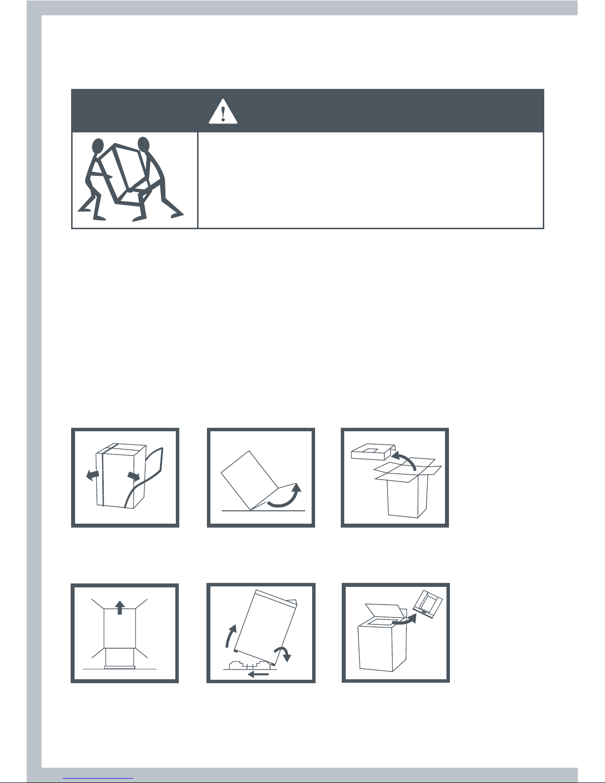
Unpacking
Make sure dryer is in a suitable location for installation.
Consider installing the dryer before the washing machine in a side by side installation, this will
allow better access to electrical and exhaust connections.
Remove Packaging
1. Remove straps.
2. Unfold the bottom flaps
on the carton.
3. Unfold the top flaps on
the carton, remove top
packer.
1.
2. 3.
4. Remove the carton
by lifting it off the
product (do not cut
the carton off ).
5. Remove the basepacker
by tilting the product
back and walking the
product off.
6. Remove the drum packer
and the tape from the
lint collector bucket in
the drum.
Tilt
Walk
off
Slide out
4. 5.
6.
Page 21
21
Installation
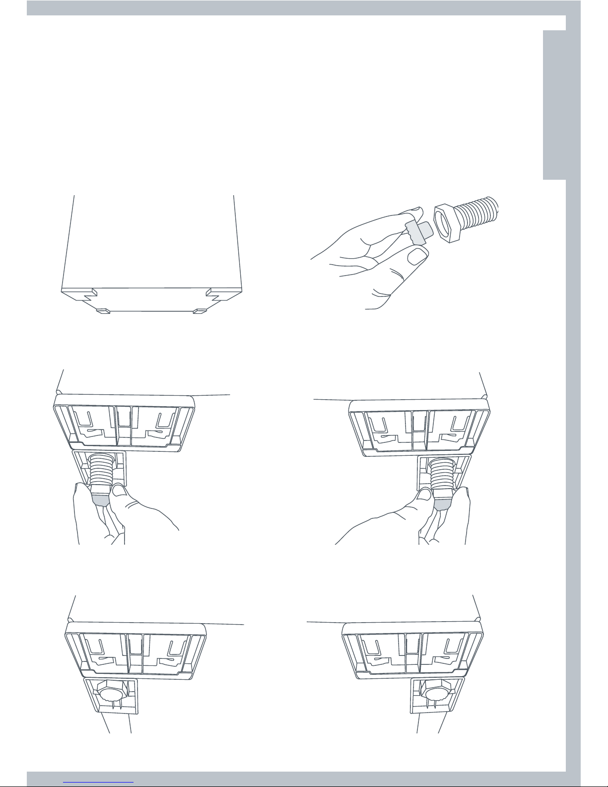
Fitting the Front Feet
Note:
Dryer is usually supplied with feet fitted and protruding the correct distance.
1
Tilt the dryer back using a hand trolley and making sure the trolley and dryer are secure.
2
Fit a rubber insert to each plastic foot as shown.
3
Screw the feet into the foot retainers on the left hand and right hand sides as shown.
4
Screw both feet in so they protrude ½” (12mm) below the bottom of the wall on the foot retainers.
US
CA
Page 22
22
Grounding Instructions for Gas and Electric Dryers
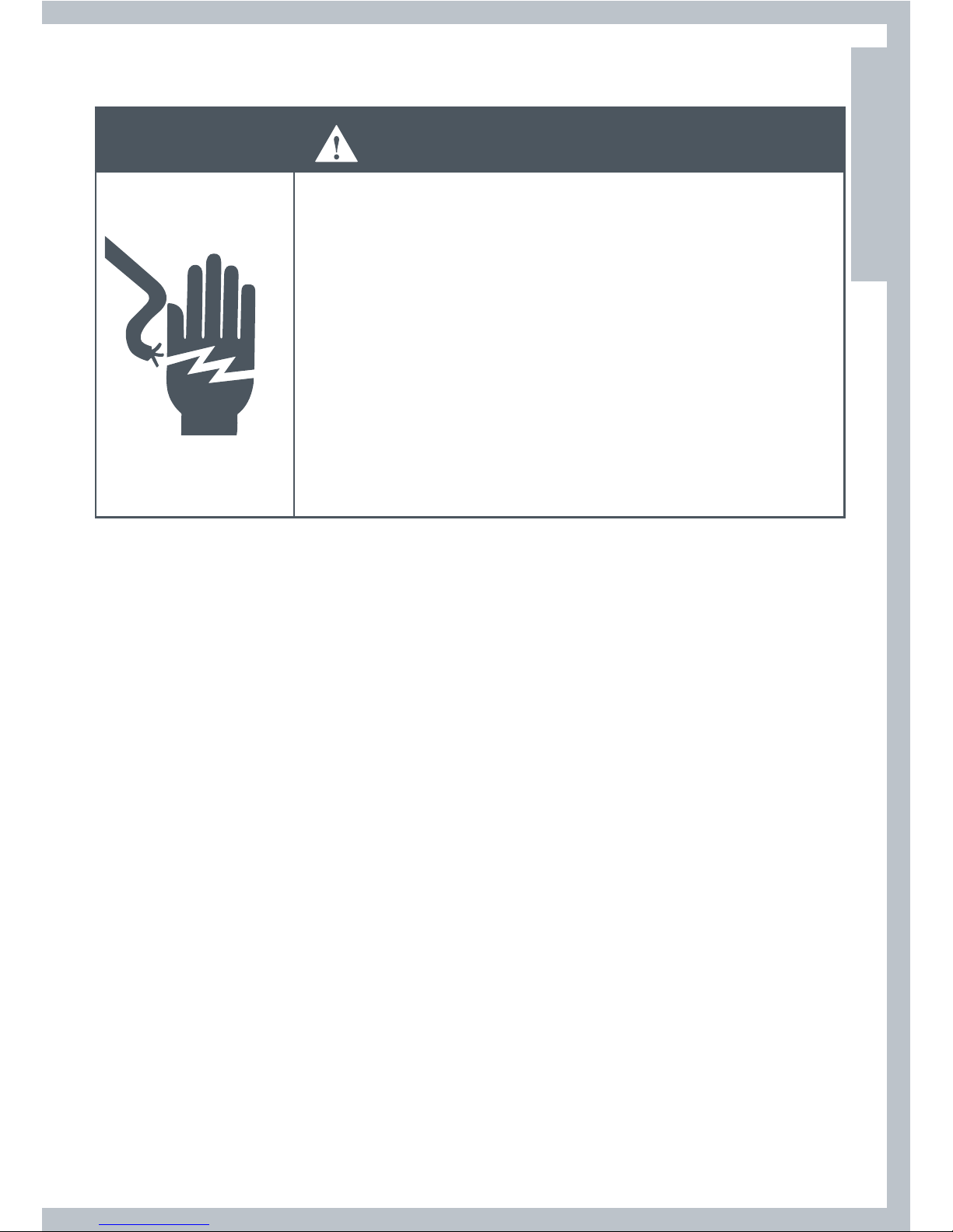
WARNING
Electrical Shock Hazard
Make sure appliance is wired or plugged into a grounded
outlet.
Do not use an adaptor.
Do not use an extension cord.
Failure to follow these instructions can result in death, fire,
or electrical shock.
WARNING
Electrical Shock Hazard
Check with a qualified electrician or serviceperson if you are
in doubt as to whether the appliance is properly grounded.
Do not modify the plug if it will not fit the outlet.
Have the proper outlet installed by a qualified electrician.
Failure to follow these instructions can result in death, fire, or
electrical shock.
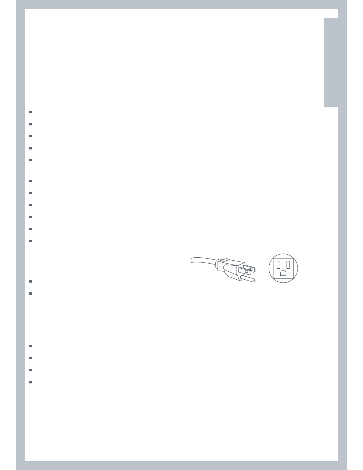
Grounding for a Cord-Connected Appliance
This appliance must be grounded. In the event of malfunction or breakdown, grounding will
reduce the risk of electric shock by providing a path of least resistance for electric current.
When this appliance is equipped with a cord having an equipment-grounding conductor and a
grounding plug, the plug must be plugged into an appropriate outlet that is properly installed
and grounded in accordance with all local codes and ordinances, or in their absence, with the
National Electrical Code ANSI/NFPA 70, or the Canadian Electrical Code, CSA C22.1. Do not cut or
remove the grounding prong from this plug.
WARNING
Improper connection of the equipment-grounding
conductor can result in a risk of electric shock. Check with
a qualified electrician or service representative if you are in
doubt as to whether the appliance is properly grounded.
Refer to pages 23 – 28 for wiring details for electric dryers.
Page 23
23
Electrical Requirements for Electric Models Only
WARNING
Electric Shock Hazard
Use a new UL approved 30-ampere power cord or direct wire
cable.
Use a UL approved strain relief.
Disconnect power before making electrical connections.
Connect neutral wire (white or center wire) to center terminal.
On all four wire installations remove the grounding link and
connect the ground wire to the green ground connecting screw.
Connect remaining 2 supply wires to remaining 2 terminals.
Securely tighten all electrical connections.
Failure to do so can result in death, fire, or electrical shock.
Note:
The wiring diagram is located in the control console.
The dryer must be plugged into or connected to an individual branch circuit, do not use an
extension cord.
The power supply must be 220/240V or 208V, 60 Hz approved alternating current electrical
service. The electrical service requirements can be found on the data label that is located on the
splash back. A 30-ampere fuse or circuit breaker is required on each of the lines.
If a power cord is used, the cord must be plugged into a 30-ampere receptacle.
The power cord is NOT provided with U.S. electric model dryers.
This dryer is supplied with the cabinet grounded through the neutral on the terminal block.
If the dryer is to be installed in (1) a new branch circuit installation, (2) a mobile home, (3) a
recreational vehicle, (4) an area where local codes do not permit grounding through the neutral
conductor, the appliance grounding link must be removed and a 4-wire power cord/cable or a
separate grounding wire must be used.
Do not reuse a power supply cord/cable from an old dryer. The power cord/cable electric supply
wiring must be retained at the dryer cabinet with a suitable UL listed strain relief.
208V Requirements
If your power supply is 208V 60 Hz, a new element kit must be fitted by a qualified electrician or
service representative (see Accessories page 9 for kit part number).
US
CA
Page 24
24
Power Supply Cord Requirements for U.S.A
for Electric Models Only
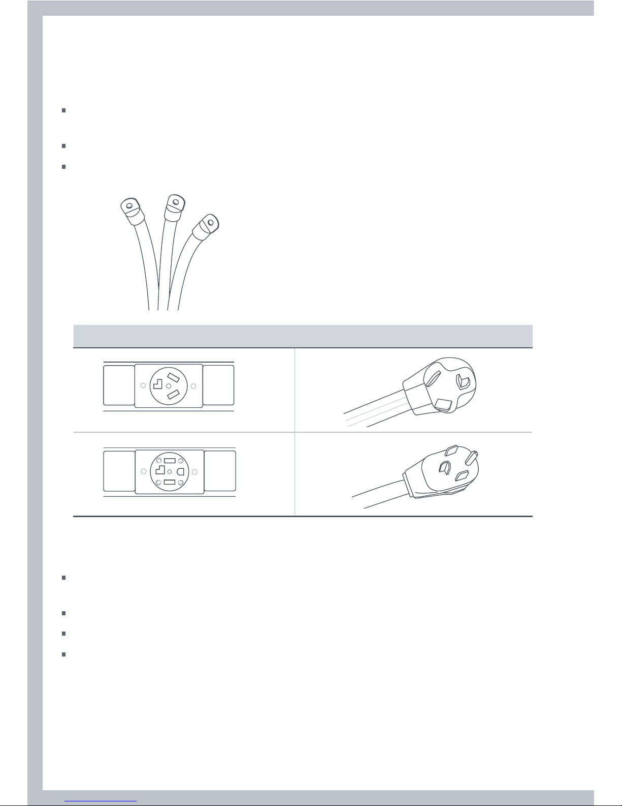
Only a UL listed power-supply cord kit a suitable length for the installation and rated 120/240 V
min, 30 A and marked with use for clothes dryers shall be used.
This shall have ring terminals to connect to the dryer.
The UL-rated strain relief included with it shall be suitable for a 1 /” (28.5mm) hole.
If your outlet looks like this Choose this power supply cord
Connecting by Direct Wire
Power supply cable must match power supply (4-wire or 3-wire) and be:
Flexible armoured or non-metallic sheathed copper cable (with ground wire). All current-carrying
wires must be insulated.
10 gauge AWG solid copper wire (do not use aluminium wire).
Suitable length for the installation.
A UL approved strain relief must be used.
Grounding for a Direct Wired Appliance
This appliance must be connected to a grounded metal permanent wiring system, or an
equipment grounding conductor must be run with the circuit conductors and connected to the
equipment-grounding terminal on the appliance.
4 wire
3 wire
Page 25
25
Electrical Connections (Electric Models Only)
Please read Electrical requirements and grounding instructions on pages 22 – 23 first.
Electric models of the dryer are manufactured for a 3-wire connection system. The dryer frame
is grounded by a link to the neutral conductor on the dryer terminal block. If local codes do
not permit grounding through the neutral, the grounding link from the terminal block must be
removed and a separate ground wire must be used.
The grounding link on the dryer must be removed for all 4-wire installations including new,
remodelled construction, or mobile homes.
These Electrical Connection instructions provide for installing the dryer in the following situations:
3-wire connection where local codes permit grounding through the neutral.
3-wire connection plus separate grounding connector where local codes do not permit
grounding through the neutral.
4-wire connection.
Each of the above connections can be made with an approved power supply cord or by direct
wiring. Each connection instruction identifies the appropriate Power Supply Cord and covers
requirements for direct wiring.
For 3-Wire Connections by Power Cords
3-wire power supply cord must have three 10 AWG copper wires and match a 3-wire receptacle
of NMEA Type10-30R.
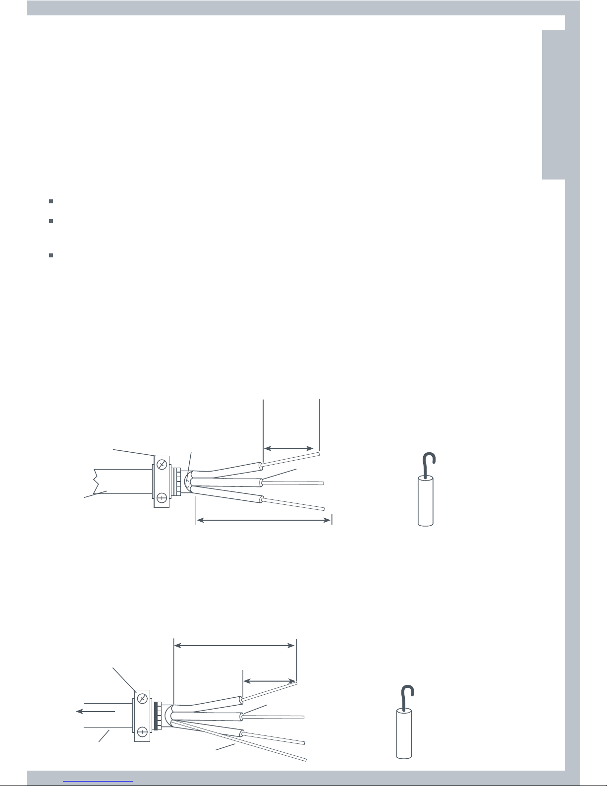
For 3-Wire Connections by Direct Wiring
10-gauge, 3-wire or,
10-gauge, 3-wire with
ground wire (Romex)
to disconnect
box
¾” UL-listed
strain relief
Three-wire with ground
wire: Bare wire cut short.
Wire not used. Dryer is
grounded through neutral
or separate grounding
1” of wires
stripped of
insulation
NEUTRAL wire
(white or center)
4 ¼”
Strip 4 ¼” of outer covering from end
of cable. Strip insulation back 1”. If
using 3-wire cable with ground wire,
cut bare wire even with outer covering.
Shape ends of wire
into a hook.
For 4-Wire Connections by Power Cords
4-wire power supply cord must have four 10 AWG copper wires and match a 4-wire receptacle of
NMEA Type14-30R. The fourth wire (ground conductor) must be identified by a green cover and
the neutral wire by a white cover.
For 4-Wire Connections by Direct Wiring
¾” UL-listed
strain relief
to disconnect
box
10-gauge, 3-wire with ground
wire (Romex)
bare ground wire
NEUTRAL wire
(white or center)
1” of wires
stripped of
insulation
4 ¼”
Strip 4 ¼” of outer covering from end of
cable. Strip insulation back 1”.
Shape ends of wire
into a hook.
US
CA
Page 26
26
3-Wire Connections
For use where local codes permit grounding through the Neutral wire.
Use approved 3-wire Power Supply Cord or a 3-wire Cable for Direct Wiring as described on page 24.
1
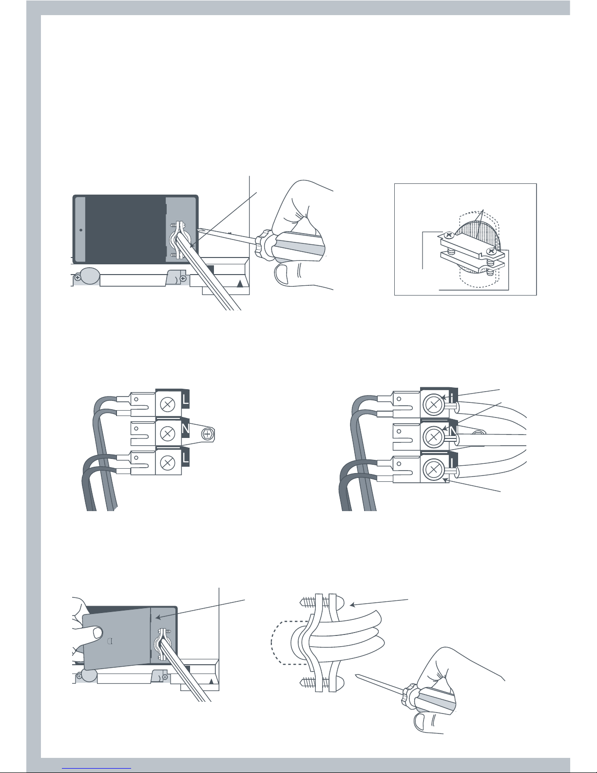
Remove the terminal block cover plate.
2
Insert the power cord with a UL listed strain relief through the hole provided in the cabinet near
the terminal block. Do not tighten strain relief screw until wiring connections are complete.
Note: a strain relief must be used.
2
strain relief
clamp sections
strain relief
screws
3
Loosen or remove the center terminal block screw. Connect the neutral wire (center) of the power
supply cord to the center terminal screw of the terminal block. Tighten screw.
4
Connect the other wires to the upper and lower terminal block screws marked with the
letter L. Tighten screws.
4
3
4
5
Refit terminal block cover by inserting the two tabs first on the rear panel of the dryer. Secure
cover with securing screw.
6
Tighten strain relief screws.
56
Page 27

27
3-Wire Connections plus separate grounding connector
For use where local codes do not permit grounding through the Neutral wire.
Use approved 3-wire Power Supply Cord or a 3-wire Cable for Direct Wiring as described on page 25.
A separate 10AWG copper grounding wire is required.
1
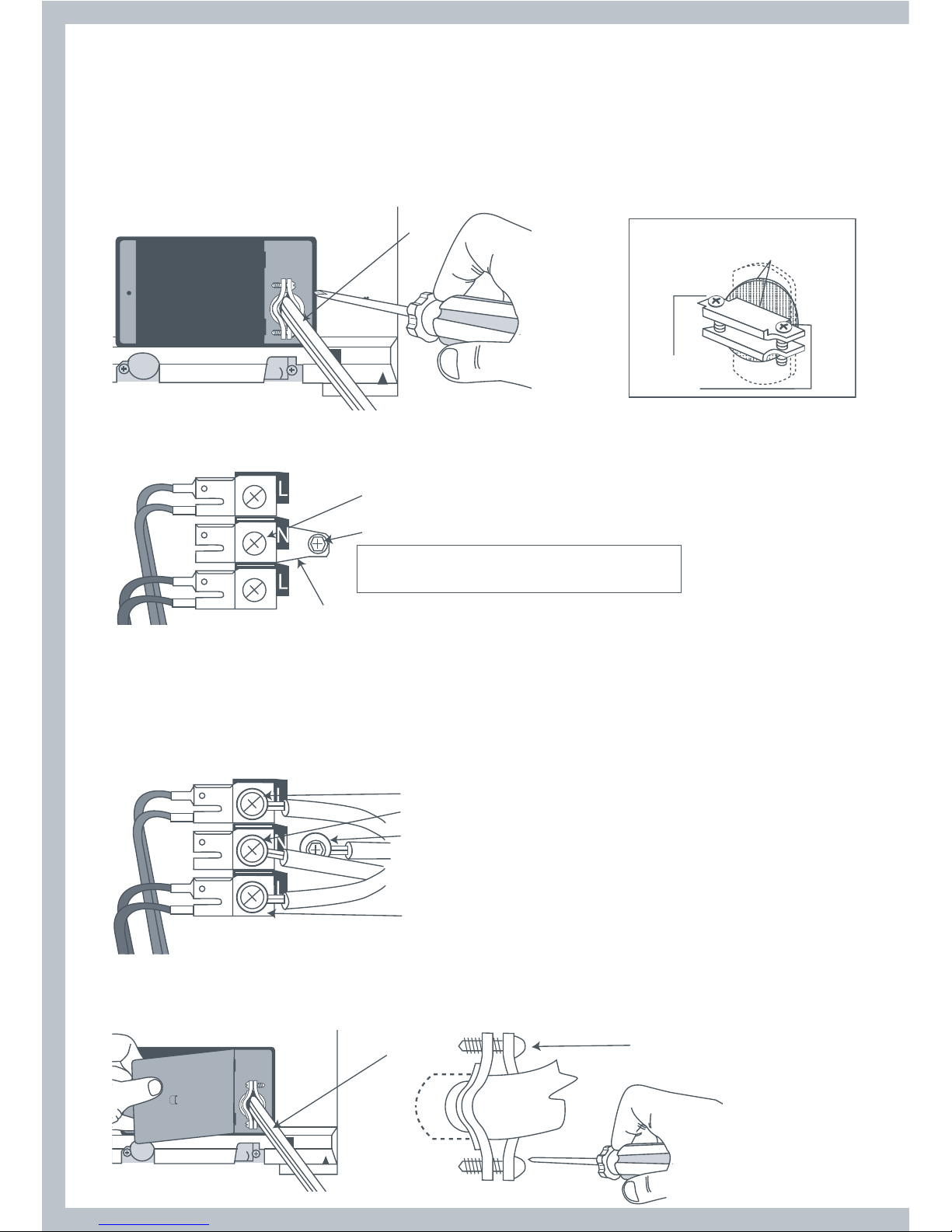
Remove the terminal block cover plate.
2
Insert the power supply cable with a UL listed strain relief through the hole provided in the cabinet
near the terminal block. Do not tighten strain relief screw until wiring connections are complete.
Note: a strain relief must be used.
2
strain relief
clamp sections
strain relief
screws
3
Remove center terminal block screw.
4
Remove appliance ground link by removing the ground connector screw (Green screw).
5
Connect a separate copper ground wire (green with yellow stripe) using the ground connector
screw (Green screw). Make sure a ring terminal is used when connecting the ground wire and that
the wire is firmly secured to an adequate grounding path.
3
4
7
6
5
7
Note: If the appliance is
moved back to a 3-wire
installation the ground
link must be refitted.
Remove link
6
Connect the neutral wire (center) of the power supply cord to the center terminal screw of the
terminal block. Tighten screw.
7
Connect the other wires to the upper and lower terminal block screws marked with the
letter L. Tighten screws.
8
Refit terminal block cover by inserting the two tabs first on the rear panel of the dryer and secure
cover with securing screw.
9
Tighten strain relief screws.
It is recommended that a qualified electrician
determine that the ground path is adequate
grounding wire
8
9
US
CA
Page 28
28
4-Wire Connections
Use approved 4-wire Power Supply Cord or a 4-wire Cable for Direct Wiring as described on page 25.
1
Remove the terminal block cover plate.
2
Insert the power supply cable with a UL listed strain relief through the hole provided in the cabinet
near the terminal block. Do not tighten strain relief screw until wiring connections are complete.
Note: a strain relief must be used.
2
strain relief
clamp sections
strain relief
screws
3
Remove center terminal block screw.
4
Remove appliance ground link by removing the ground connector screw (green screw).
3
4
Note: If the appliance is moved back to a 3-wire
installation the ground link must be refitted.
Remove link
5
Connect ground wire (green) of the power supply cord to the ground conductor green screw.
Tighten screw.
6
Connect the neutral wire (white) of the power supply cord to the center terminal screw of the
terminal block. Tighten screw.
7
Connect the red wire and black wire to the upper and lower terminal block screws marked with the
letter L. Tighten screws.
7
6
5
7
8
Refit terminal block cover by inserting the two tabs first on the rear panel of the dryer and secure
cover with securing screw.
9
Tighten Strain Relief screws.
8
9
Page 29
29
Gas Requirements (Gas Models Only)
The installation must conform with Local Codes, or in the absence of Local Codes, to the National
Fuel Gas Code ANSI Z223.1/NFPA 54 or the Canadian Natural Gas and Propane Installation Code,
CSA B149.1.
WARNING
Explosion Hazard
Installations must be performed by a qualified or licensed
contractor, plumber, or gasfitter qualified or licensed by
the state, province, or region where this appliance is being
installed.
Use a new AGA or CSA approved gas supply line.
Install a shut-off valve in an accessible place.
Only use a gas shut-off valve approved for use within the state,
province, or region where this appliance is being installed.
Securely tighten all gas connections.
If connecting to LP Gas, have a qualified person make sure
gas pressure does not exceed 13” (33 cm) water column.
Failure to follow these instructions can result in death,
explosion, or fire.
Gas type
Your dryer must have the correct burner for the type of gas in your home. Burner information is
located on the rating plate located on the rear of the console. If this information does not agree
with
the type of gas available in your home, contact your local Fisher & Paykel supplier or service
center.
Natural Gas
This dryer is supplied ready for use with Natural Gas.
It is design certified by UL International for LP (Propane or Butane) Gases with the appropriate
conversion.
LP Gas Conversion
If the dryer is to be operated on LP (Liquid Propane or Butane) Gas, the dryer must be converted.
To do so, use only the approved Fisher & Paykel conversion kit listed in Accessories on page 9.
Do not use with a different gas without consulting the serving gas supplier.
The dryer must be converted for safe and proper performance by qualified service or installation
personel.
Conversion kits for Natural and LP Gas are available from your local Fisher & Paykel Dealer (see
Accessories page 9). If other conversions are required, check with your local gas utility for specific
information concerning conversion requirements.
US
CA
Page 30
30
Connecting Gas to Your Dryer (Gas Models Only)
Use compound or thread tape appropriate to the gas type that is to be used (Natural or LP Gas),
on the male threads of all non-flared connections.
Never use an open flame to test for gas leaks.
This dryer will operate satisfactorily up to altitudes of 6500ft (2000m) above sea level at the
BTU rating indicated on the model/serial plate. Burner input adjustments may be required if
operating above this elevation.
The dryer must be disconnected from the gas supply system during any pressure testing.
Gas Ignition
This dryer has an automatic ignition system to ignite the burner. There is no pilot flame burning
in this dryer.
Connecting to the Gas Supply
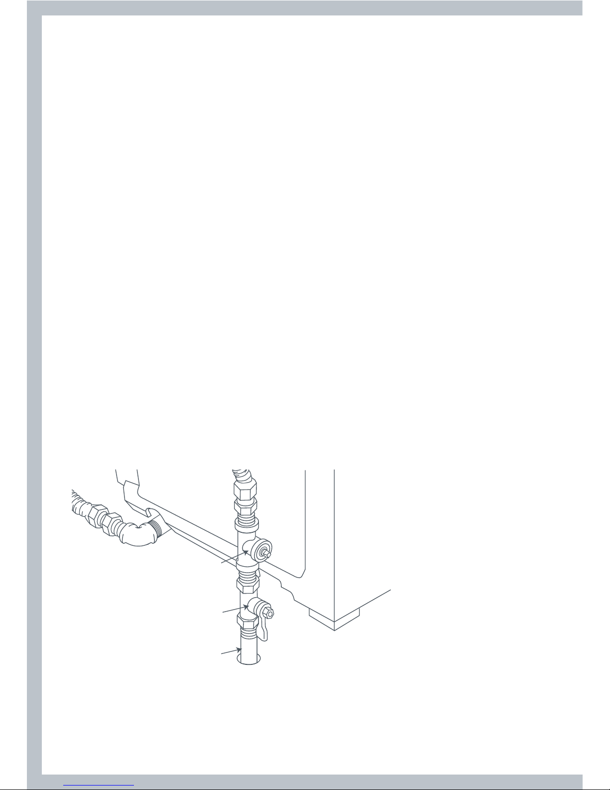
1
The gas supply line should be ½ inch.
2
An individual manual shut-off valve must be installed on the gas supply line within 6ft (1.8m) of
the dryer, in accordance with the National Fuel Gas Code ANSI Z223.1/NFPA 54 for the United
States or in accordance with the B149.1 Natural Gas and Propane Installation Code for Canada.
3
An ⁄ inch NPT plugged tapping must be installed to allow the gas inlet pressure to be checked.
It must be accessible for the test gauge connection and immediately upstream of the gas
connection to the dryer.
⁄” NPT plugged tapping
Gas shut–off valve
⁄” NPT gas supply line
Page 31

31
Connecting Gas to Your Dryer (Gas Models Only)
4
A listed connector in compliance with ANSI Z21.24/CSA6.10 must be used to connect the dryer
to the gas supply.
5
If flexible tubing is used, an elbow should be installed on the pipe at the back of the dryer for
the flexible tube to be connected to. This will minimize damage to the tube when the dryer is
moved back. Use a flexible tubing connection kit that has designed for use on a clothes dryer.
This kit should have the unions necessary to join to the ends of the tubing. Be sure to follow all
instructions supplied with the kit.
6
Copper tubing should not be used for Natural Gas and if used for LP Gas, it must be LP Gas
compatible.
7
Disconnect and discard old flexible tubing.
8
The gas pipe that comes out of the rear of your dryer has on it a ⁄” NPT male thread. Remove
the protective cap and apply sealing compound or tape to the thread. Thread sealant should be
appropriate for the type of gas to be used.
Apply thread
sealant
Remove cap
⁄” NPT pipe thread
Elbow required
for flexible tubing
Completing the Connection
9
Use wrenches to tighten all joints but do not over tighten.
10
Open the gas supply valve and check all joints by brushing on a non-corrosive leak-detecting
solution. Bubbling will indicate a leak. If any leaks are found, close the valve immediately and
correct the leaks. Retest and repeat until no leaks are found.
US
CA
Page 32

32
Level Machine
Check the dryer is level, and make necessary adjustments to the
front levelling feet. The rear levelling feet are self adjusting.
Final Installation Check List
Check that:
No plastic or flexible metal foil is used in the exhaust ducting.
Exhaust is rigid ducting or thick wall flexible metal ducting.
All joints in the ducting are made with duct tape. It must not be connected with screws or other
fastening devices which extend into the inside of the duct.
Ducting is clean and is connected to the dryer.
Inserts are fitted to the two front feet.
Dryer is level across the front.
Additionally for Electric Dryer Models Only, Check:
If installation is 208V, special element kit has been fitted (see page 23).
Dryer is plugged or directly wired into an approved fitting and is properly grounded.
Dryer starts, heats, cools and shuts off.
Customer has been shown how to use the dryer.
Additionally for Gas Dryer Models Only, Check:
Dryer is plugged into an approved fitting and is properly grounded.
All fittings in the gas line are tested for leaks.
Exhaust temperature increases, to confirm ignition has occurred.
– If ignition does not occur initially, it may be due to air in the gas line or low voltage power supply.
– The gas regulator valve may fail to open if the power supply falls below 105 Volts.
– If the gas fails to flow or does not ignite, the dryer will automatically switch off.
Customer has been shown how to use the dryer.
Note:
All dryers have a drum reversal feature to reduce clothes tangle. Throughout the drying cycle
the motor will run for four minutes, then stop and run in the opposite direction for forty seconds
before reversing again.
WARNING!
Electric Shock Hazard
Read and follow the Important safety instructions outlined in this User
Guide before operating this appliance, pages 6 – 8.
Failure to do so can result in death, electric shock, fire or injury to persons.
Close supervision is necessary if this dryer is used by or near children. Do not allow children to
play inside, around or with this dryer or any other appliance.
Page 33

33
Features
Smart Loading
The new ergonomic design of this dryer means less bending.
Simply move clothes from the washer to the dryer with
minimal effort.
Superior Clothes Care
Superior clothes care is accomplished by an efficient high airflow
fan and careful heat control. The Intuitive™ dryer provides the
right heat for temperature sensitive delicate articles while still
efficiently drying more robust regular and denim loads.
Reverse Action Tumbling
The drum reverses regularly, so your clothes dry more evenly
without roping or tangling.
Lint Bucket
The lint filter is automatically scraped clean during the drying
cycle and the lint is deposited into the lint bucket. No touching
or scraping lint any more. Airflow is more efficient as it is never
restricted by a blocked filter.
Perfect with the Fisher & Paykel Intuitive™ Washer
The dryer combined with the Intuitive™ washer’s superior spin
performance and quick cycle times will cut laundry turn around
time by up to one third, reducing the time you spend doing
laundry.
Stainless Steel Drum
Being stainless steel, this drum is not only more hygienic, it’s also
more resilient and easier to keep looking good.
US
CA
Page 34

34
Operating Instructions Control Panel
A. Sorting
Sort clothes of similar types and loads that take similar times to dry.
(Refer to Sorting page 46).
B. Loading
Load clothes no higher than the transparent section of the lint
bucket. (Refer to Loading page 46).
C. Lint Bucket
Check to see if the lint bucket needs emptying. Empty before
the lint reaches the top of the transparent section (refer to Lint
Bucket page 47).
D. Press Power
E. Fabric Type
Choose the fabric type that most represents the items in your load. Your dryer defaults to a MIXED
fabric type, to change it press either the UP or DOWN arrow. A description of each cycle will pop
up on the display screen as you scroll through the lights. (For more information on the cycles refer
to page 37).
If you want to use AIR DRY, press the DOWN arrow until AIR DRY light is lit.
Empty before this
level is reached
D
E GF
Page 35

35
Control Panel
F. How Dry?
Choose how dry you want to dry your clothes, There are 5 dryness settings you can choose
between, EXTRA DRY, EXTRA DRY/DRY, DRY, DAMP/DRY, or DAMP. (Refer to page 39 for
descriptions). Press the HOW DRY button until the setting you want is lit.
G. Start
Press START/PAUSE to start your machine.
H. Display screen
Shows you what options you have selected and/or any Lifecycles™ you may have chosen. The
display screen also shows you the progress of the load as well as displaying messages to help you
with the overall running of your machine.
I. Options Menu
Choose any options you want by scrolling through the OPTIONS MENU. Press the OPTIONS button.
Scroll through the options by using the UP and DOWN arrows. To select an OPTION, press ADJUST.
Once a selection has been made press HOME to return to the main screen (Refer to page 42).
J. Lifecycles™
There are 10 unique Lifecycles™ that have been specifically designed to make drying simpler
and easier.
Family Specials Bulky Items
Allergy Freshen Up Blankets
Towels Warm Up Jeans
Shirts Dry Clean Comforter
Lingerie
(Refer to Lifecycles™ page 44).
H
J
I
US
CA
Page 36

36
Quick Start
WARNING
To reduce the risk of fire, electric shock or personal injury, read the IMPORTANT
SAFETY INSTRUCTIONS before operating this appliance.
WARNING
Fire Hazard
Only dry fabrics that have been washed with water.
Do not use heat to dry articles containing foam rubber or
similarly textured rubber-like materials. Dry on the Air Dry cycle.
A clothes dryer produces combustible lint and must be
exhausted outdoors. Take care to prevent the accumulation of
lint around the exhaust opening and in the surrounding area.
Failure to follow these instructions can result in death or
personal injury.
WARNING
Explosion Hazard
Keep flammable materials and vapors, such as gasoline, away
from dryer.
No washer can completely remove oil.
Do not dry anything that has ever had gasoline, oil or anything
flammable on it (including cooking oils).
Failure to follow these instructions can result in death or
personal injury.
1
Press POWER
2
Choose your Fabric Type
3
Choose How Dry you want your clothes
4
Press START
1
2 3 4
Page 37

37
Fabric Type
The Intuitive™ dryer is capable of drying many
different fabric types. On the display screen the
FABRIC TYPE button is located next to the POWER
button. Use the UP and DOWN arrows to alter the
fabric type you wish to dry with.
When you turn your Intuitive™ dryer on it will
automatically select the MIXED fabric type. This
setting is suitable for drying your everyday garments,
e.g. t-shirts, trackpants, sweatshirts etc.
To change the FABRIC TYPE, press either the UP or DOWN Arrow.
Select a fabric type that matches the type of load you are drying. Different fabrics have different
drying requirements, so it is important to choose the cycle that best describes the load. For
example if your load contains mainly delicate items it is best you select the LIGHT Fabric Type.
Always follow manufacturer’s care label instructions when drying.
If you are unsure of the temperature to select for a load, it’s best to select a lower heat rather
than a higher heat, e.g. the LIGHT or CASUAL setting instead of the MIXED setting.
There are five FABRIC TYPES programmed into your Intuitive™ dryer as well as an AIR DRY option.
HEAVY
The HEAVY setting has been designed to provide a long, high heat cycle for heavy fabrics and
denims that tend to have thick and bulky seams. This setting dries for longer intervals to ensure
heavy items are fully dry.
MIXED
The MIXED setting has a high heat for drying everyday clothing and linen. This cycle is suitable
for most garments labelled “Tumble Dry”.
CASUAL
The CASUAL setting uses a medium heat for lightweight fabrics. It is ideal for lightweight cottons
and items labelled “ tumble with a medium heat”
DRY AND WEAR
The DRY AND WEAR setting uses a medium heat combined with the selection of the WRINKLE
FREE option. Ideal for any types of garments where you want to wear them straight away. The
Wrinkle Free option is automatically selected so there is no need to iron clothes when you
remove them from your dryer. Once drying is completed, clothes are automatically turned every
5 minutes, without heat, to reduce the likelihood of creases and wrinkles developing. This will
continue for up to 24 hours or until you stop the dryer.
US
CA
Page 38

38
Fabric Type
LIGHT
The LIGHT setting is ideal for delicate or heat sensitive items. Use this setting when care-labels
recommend low heat settings or for garments with a synthetic fiber content, where overheating
could cause damage to fibers.
AIR DRY
The AIR DRY option is for items requiring drying without heat. Perfect for airing clothes or to
freshen up garments that have been packed in a suitcase or drawer.
Press the FABRIC TYPE button DOWN until the AIR DRY light is glowing. A second screen will
automatically pop up, to show AIR DRY time options. Use the ADJUST button to choose the
length of time you wish to dry your load for.
Page 39

39
How Dry?
AUTO SENSING
Autosensing is automatically selected when your
Intuitive™ dryer is turned on. When selected, your
dryer automatically senses the dryness level of the
load and turns off when the clothes are dry. Intuitive’s
internal computer measures the moisture content of
the load using metal sensor bars and together with a
temperature sensor determine when the clothes have
reached the selected dryness level.
For optimum clothes care match the cycle to the load. AUTO SENSING often provides the best
results and leads to lower energy costs than TIME DRY.
There are five different dryness levels to choose from:
EXTRA DRY
DRY/EXTRA DRY
DRY
DAMP/DRY
DAMP
The dryer defaults to the DRY Setting. To change this
press the HOW DRY button until the dryness setting
you want is highlighted. If you choose the DAMP/DRY
or DRY/EXTRA DRY setting two lights will be displayed.
At the end of the cycle if the clothes are still damp or
are too dry next time adjust the dryness level on the
touch pad to meet your personal preferences.
Dryness Level Descriptions
EXTRA DRY
This is mainly for items that you want to store (i.e. place in a drawer, cupboard or wardrobe). By
using this setting you eliminate the possibility of ‘musty smells’ that commonly occur when items
are stored in a damp state.
DRY
Dries clothes to a level where they are considered ‘dry’, so garments can be worn immediately.
DAMP
Dries the clothes to a level where they are considered ‘moist’. It is designed for delicate, lightweight fabrics and articles of clothing which you want to iron-dry.
US
CA
Page 40

40
Display Screen
The display screen on the right hand side of the panel
shows you what the machine is doing during the cycle. The
display screen also shows you the different drying options
available. When you first turn your Intuitive™ dryer on it will
briefly display the message “Welcome to Intuitive”. The main
screen then appears with a big smiley face and tells you the
machine is READY TO DRY, the setting it has defaulted to
and also displays any options/lifecycles you select.
All About the Options Button…
Your Intuitive™ dryer has a menu of drying options you can use. The buttons and the display
screen on the right hand side of the panel are used to select and display the different options.
To Select a Drying Option:
1
Push either the Options UP or Options DOWN arrow. The
Options menu will then be displayed.
2
Scroll through the options by using either the UP or DOWN
arrows. To select an option use the ADJUST button. The
option will be highlighted to show you have selected it.
3
Press HOME, the display will return to the home screen,
where your selected drying option(s) will be displayed.
4
To start your dryer press START/PAUSE.
Note:
If you want to change any of the drying options while your machine is running you will need to
press START/PAUSE before changing an option or setting.
Page 41

41
Progress Screen
During the cycle the display screen shows you the progress of your load by displaying a series of
messages that indicate what stage the dryer is up to. The display screen also scrolls through any
options you may have chosen.
When you first start your dryer the words SENSING Dampness will appear on the screen. During
this period the dryer is sensing the dampness of your load.
Once the dryer has sensed your loads dampness the words
DRYING will appear on the screen. (If you have chosen
AIR DRY the word AIRING will appear). This message is
displayed for the majority of the cycle letting you know it is
in the process of drying your load. The dryer will continue
to display the word DRYING until it senses that your load is
becoming damp.
The word DAMP will appear when the dryer senses that the load is becoming dry. This is the
stage that you can remove delicate garments you wish to hang dry.
The word DAMP/DRY appears when the dryer senses that the clothes are almost dry. It will
continue drying until it reaches the HOW DRY level you have selected. Once it reaches the
dryness setting you have chosen your dryer will progress into COOLING.
You can select an option in the Options menu to remind you to remove your delicates early
(refer to page 43).
The word COOLING will appear when dryer is in the
process of cooling down the dry load. This is where the
load is tumbled with no heat, decreasing the need for
ironing. COOLING will continue until the dryer senses the
clothes have been cooled down sufficiently. The exception
is TIME DRY which has a fixed COOLING period.
US
CA
Page 42

42
The Options
For all the options mentioned below select the OPTIONS
menu (by pressing the UP Options arrow). Use the Options
arrows to scroll through the options until the one you want
is displayed.
Press ADJUST to select it and HOME to return to the main
screen.
1. WRINKLE FREE
The WRINKLE FREE option minimizes the likelihood of creases or wrinkles forming in clothes, if
you are not able to unload the dryer straight away. This option rotates the drum periodically after
the cycle has finished. This tumbling action, combined with blowing cool air through the clothes,
helps garments to remain wrinkle free.
WRINKLE FREE uses very little power and will continue for
up to 24 hours or until the user turns the dryer off. After
completing each tumble Intuitive™ dryer will give an end
of cycle beep to remind you that the load is dry and can
be removed.
Scroll to Option screen 1, press the ADJUST button to
change setting, press HOME to save your setting.
To stop the dryer press either POWER or START/PAUSE.
Intuitive™ dryer will open the drum door and unlock the lid,
so you can remove your clothes.
WRINKLE FREE can be selected on any cycle.
2. TIME DRY
There are three timed cycles. You can choose between
20, 40 and 80 minutes. A COOLING period of 10 minutes
is included in the 80-minute and 40-minute cycle. The 20
minute cycle has a 5-minute COOL DOWN period.
Scroll to Option screen 1, press the ADJUST button to
change setting, press HOME to save your setting.
To select a timed cycle, press the ADJUST button to move to the time you wish to dry for. Your
Intuitive™ dryer will default to 40 minutes.
If you choose to select TIME DRY, please note the dryer will not sense when your clothes are dry.
This may increase the chance of over-drying.
We recommend that you dry your clothes for a slightly shorter time than you think they need, or
check on them regularly (to avoid over-drying).
Page 43

43
The Options
3. END OF CYCLE BEEPS
You can change the number of beeps your Intuitive™ dryer sounds at the end of the cycle. Scroll
to Options screen 3, use the ADJUST button to move to your desired preference. Press HOME to
save your selection.
4. REMINDER – REMOVE DELICATES EARLY
If you wish, your Intuitive™ dryer can remind you to
remove your delicate items while they are still slightly
damp. This can be useful if you have a mixture of light
and heavy fabrics in your load. Your dryer will beep and
display a message when it senses that the load is nearly
dry. You will then be able to remove delicate items and
the rest of the load will continue the cycle.
To activate the reminder, scroll to Options screen 4, press the ADJUST button to select ON, then
press HOME to save your setting.
5. REMINDER – EMPTY LINT BUCKET
This reminder is automatically selected when you receive your dryer. If you do not wish to be
reminded every 5 cycles to remove the lint from the lint bucket you can turn the reminder off.
Scroll to Options screen 5, press the ADJUST button to select OFF, then press HOME to save your
setting (also refer to page 47).
6. REMINDER – ADD SOFTENER SHEETS
If you add fabric softener sheets to your dryer, you can select this option to remind you to add
them at the beginning of each cycle. To activate the reminder, scroll to Options screen 6, press
the ADJUST button to select ON, then press HOME to save your setting.
7. CYCLE TIPS
Cycle tips screens are displayed to help you to remember what each cycle does.
For example, when you select Fabric Type = Mixed, after 1 second a cycle tips screen will appear
with the words “Mixed – High heat for everyday cottons”.
Once you have become familiar with your dryer you may wish to switch these tips off. Scroll to
Options screen 7, press the ADJUST button to select OFF, then press HOME to save your setting.
8. TROUBLE SHOOTING
Your Intuitive™ dryer provides basic Trouble Shooting tips on screen. Scroll to Options screen 8,
press the ADJUST button to select the topic that you require assistance with. The topic will then
be displayed on the screen. Use the Options down arrow to scroll through possible solutions.
For more detailed Trouble Shooting information refer to pages 52 – 53 of this guide, or If Your
Intuitive™ Dryer Beeps For Help, page 51.
US
CA
Page 44

44
Lifecycles™
Your Intuitive™ dryer has a range of special, pre-programmed Lifecycles™ to make doing the laundry
even easier.
Push the LIFECYCLES button.
Use the OPTIONS button to scroll through the 3
Lifecycles™ menus, or you can press the LIFECYCLES
button repeatedly.
Use the ADJUST button to select a lifecycle.
Press HOME to return to the main screen.
L1 Family
ALLERGY
This cycle has been designed to complement the Allergy cycle currently available in the Intuitive™
washer. It is recommended for both allergy sufferers and for piece of mind in times of family illness.
This cycle uses a high heat to ensure that dust mites and bacteria populations are decimated. It has
been designed primarily for sheets and everyday clothing, and is not recommended for garments
that are heat sensitive.
TOWELS
Heavy Fabric Type, Dry/Extra Dry dryness level, with Autosensing.
Specifically designed for towels.
SHIRTS
This cycle has been developed for business and dress shirts. It uses
a medium heat, Autosensing selected, Dry dryness level, with the
WRINKLE FREE option selected to reduce wrinkling.
LINGERIE
This is an extra gentle cycle for delicate fabrics. It has been designed for garments that you previously
may have been reluctant to put into the dryer e.g. lingerie and synthetics. This cycle dries using the
Light Fabric Type setting, Autosensing, the Dry dryness level, and has the WRINKLE FREE option
selected to reduce wrinkling. We recommend placing undergarments in a net bag for extra protection.
L2 Special Items
FRESHEN UP
This cycle tumbles for 20 minutes without heat. It has been designed to freshen clean clothes that
have been stored in a cupboard, drawer or packed in a suitcase.
WARM UP
Warm Up is designed to heat clothes for 20 minutes so that they are warm to the touch. Warm your
pyjamas before bed on a cold night, or warm towels while you are in the shower. The Warm Up
cycle uses a Casual Fabric Type and is not recommended for garments that are heat sensitive.
DRY CLEAN
A cycle specially designed for “In Dryer” dry clean products. This cycle has a medium heat for 40
minutes and has the WRINKLE FREE option selected. Follow the manufacturers instructions for how
to prepare the load. At the end of the cycle remove the dry cleaning product from the machine
and continue to follow the dry cleaning product’s instructions.
Important:
Ensure the dry cleaning product is recommended for use in a domestic dryer.
Page 45

45
Lifecycles™
L3 Bulky Items
BLANKETS
You will need to check the care label to make sure that
the item can be dried in the dryer.
It is a good idea to include 4 – 5 medium sized towels
along with the blanket for cushioning. This will reduce
shrinkage from over tumbling. If you are drying more
than one blanket, ensure that they do not sit higher than
the top of the lint bucket, otherwise there will not be
enough room for them to tumble.
This cycle uses the lowest heat setting, the Light Fabric Type setting and runs with the
Damp/Dry How Dry setting.
On completion, remove the blanket, shake and if needed stretch the blanket back to its original
shape. Place back in the dryer and repeat until the blanket is dry.
Important:
It is important to completely dry the blanket to prevent mildew from forming.
JEANS
This cycle has been designed for drying denims or similar heavyweight items like jeans and
thick towels, which are bulky or have thick seams. The Jeans lifecycle has been tailored to dry
these items. This cycle uses High Heat, the Heavy Fabric Type, and has the WRINKLE FREE
option selected.
COMFORTER
Comforters are very bulky items and can be difficult to dry.
It is important before you put your comforter in the dryer that you check to make sure the
care label says that it can be dried in a clothes dryer.
This cycle uses Autosensing, and dries on the lowest heat setting. The Fabric Type setting used
is Light, How Dry level is Dry/Extra Dry. It is a good idea to check the garment throughout the
cycle to ensure even drying. If the item contains feathers, add a heavy item (e.g. a towel tied in
a knot) to the load to help fluff the comforter.
Ensure the load does not sit higher than the top of the lint bucket before starting the cycle.
US
CA
Page 46

46
Using Your Dryer
Check the care labels inside the garments to determine whether the garment manufacturer
recommends tumble-drying.
Sorting
It is best that you sort your garments before placing them
into the dryer. Sort into loads of similar types, and loads that
take similar times to dry.
Heavier items (e.g. towels, t-shirts and flannel sheets) are
best dried separately from lightweight items (e.g. synthetics,
poly-cotton sheets and shirts). This prevents the possibility of
some items becoming over-dried whilst others are still damp.
It will also help to extend the life of your clothing and linen.
Drying your clothes as soon as the washer has finished will
decrease the chance of wrinkles and the chance of dye
transfer from colored items to white items.
We recommend that articles of clothing with screen-printing
are turned inside out to ensure the screen-printing does
not stick to the drum. Garments with hooks or zippers need
to be fastened and where possible turned inside out. Place
undergarments in a net bag to provide protection from other
items in the load.
Loading
Garments need to be loaded properly to reduce the
likelihood of them wrinkling and to ensure the load is dried
evenly. Make sure there is ample room for the garments to
tumble freely while drying. Load in terms of the space the
garments take up when dry, rather than when they are wet.
The general rule is one wash load = one dryer load.
Only load the dryer up to the top of the transparent
section of the lint bucket. Loading any higher may result in
uneven drying, tangling, wrinkling and the dryer becoming
overloaded.
It is a good idea to dry ‘permanent press’ type garments
together in a separate cycle with the WRINKLE FREE
option turned on. This will help reduce wrinkles and the
need for ironing.
Load no higher
than here
Page 47

47
Using Your Dryer
Lint Bucket
The Intuitive™ dryer’s lint removal system is unique. Unlike
other dryers, the Intuitive™ dryer automatically removes the
lint for you, from the lint screen – all you have to do is tip
the lint out!
The lint filter is hidden behind the lint bucket. As the air
passes through this filter the lint is caught on the fine
mesh. Once the lint is about ⁄” (2mm) thick it comes into
contact with a scraper which deposits it into the bucket.
This process is automatically performed every time lint
builds up on the filter.
Apart from the benefit of not having to scrape the lint
after every cycle, it also means the drying efficiency is not
affected by lint build-up during the drying cycle.
The lint bucket is located inside the dryer on the left-hand
side. You can remove it by gently pulling the handle and
lifting outwards. It slots easily back into place.
This lint bucket does not need to be cleaned as regularly
as other dryer’s lint filters. The lint bucket only needs to
be emptied before the lint reaches the top of the
transparent section.
It is important that you run your dryer with the lint bucket in place at all times.
Empty before this
level is reached
US
CA
Page 48

48
Lid Lock
Your Intuitive™ dryer locks it’s lid at the start of the
drying cycle, providing added safety for you and your
family while it is operating. This lock ensures the lid
cannot be opened while the drum is rotating.
A lidlock symbol (padlock) appears in the corner of the
screen when locked (it disappears when unlocked).
If the lidlock symbol is flashing the lid is in the process
of being unlocked. During this stage, the lid still cannot
be lifted.
The lid must be closed before the drying cycle can start. If START/
PAUS E is pressed with the lid open, the machine will beep and a
message will appear in the display screen Saying “Please close the lid
Press start to continue”, to signal that the lid needs to be closed.
Once the lid has been closed and START/PAUSE is pressed, the LID
LOCK will be activated and the drying cycle will begin.
Power Failure
If the power is cut while your Intuitive™ dryer is operating, the lid will be unlocked. In some
circumstances the drum door may not be automatically opened. If this occurs it is best if the
dryer is not interfered with. When the power is restored the dryer will automatically resume
operating. However if it does not automatically open, first close the lid and start the dryer in the
usual manner, after 5 seconds press START/PAUSE. This will cause Intuitive™ to open correctly
with the lid unlocked.
If it is absolutely necessary to remove some items before power is
restored follow the steps below:
1
Ensure the dryer is disconnected from the power supply.
2
Open the lid (this will already be unlocked).
3
On the left hand side of the dryer there is a thumb tab that appears
when the drum is closed. Press the thumb tab, while rotating the drum
by hand away from you (push the drum towards the back of the dryer).
4
Hold the thumb tab down until the drum starts opening.
5
Keep rotating the drum until it is fully open and it comes to a stop.
6
Now you can remove items from the dryer drum.
7
Close the lid once you have removed desired items.
8
Re-connect the power supply to your dryer.
The drum door will automatically close and the dryer will resume
normal operation when power is restored.
Hold thumb
tab down
Push
Page 49

49
Care Labels
Below is a selection of care label symbols that garment manufacturers use to show how their
garments should be dried. We’ve converted these symbols into the cycles and heat settings
that we recommend you use in the Intuitive™ dryer. By following our recommendations, you can
ensure that your clothes will retain their appearance over time.
Tumble
Dry Symbols
Normal Permanent
Press
Delicate Do not
Tumble Dry
Fabric Type We
Recommend
HEAVY or
MIXED
CASUAL LIGHT
Do not place
in Dryer
Tumble
Dry Symbols
Any Heat High Medium Low No Heat
Fabric Type We
Recommend
Any Cycle
HEAVY or
MIXED
CASUAL LIGHT AIR DRY
Additional Drying
Instructions
Hang to Dry Drip Dry Dry in Shade Dry Flat
Do not place articles with these symbols in the dryer.
US
CA
Page 50

50
Cleaning
Clean your dryer with a soft damp cloth and wipe dry. Do not use
scouring cleaners as they can damage the paint and plastic surfaces.
Removing the Lid
You can remove the lid for cleaning. Open the lid fully, hold one side
with one hand and tap the other side with an upwards motion. To
replace the lid, hold the lid vertically and align both hinges before
clicking back into place.
Pre-Treatment Sprays
Do not use pre-treatment sprays or liquids on or near your dryer as they can damage your
machine’s control panel as well as any of its plastic parts. Damage to your dryer caused by pre-
treatment products will not be covered by your warranty.
Stains
If stains appear inside the drum of your machine, mix a detergent and water paste (or use a non-
flammable liquid cleaner) and wipe over the stain with a soft cloth. Then tumble old towels for
20 – 40 minutes on the AIR DRY setting to remove all traces of the cleaner.
Lint Bucket
The lint bucket will need to be emptied before the lint reaches the top of the transparent
section. A lint bucket that is not full ensures your clothes will remain lint-free and your dryer will
operate at maximum efficiency.
Venting
Inspect and clean all ducting at least once a year to remove accumulated lint. Check frequently
that any damper on the exhaust hood moves sufficiently and opens and shuts freely.
Ensure that the area around the dryer is kept clear and free from combustible materials, gasoline
and other flammable vapors or liquids. Ensure also that the dyer area is kept clear and free from
items that would obstruct the flow of combustion and ventilation air.
Page 51

51
If Your Intuitive™ Dryer Beeps For Help
Your Intuitive™ dryer is capable of diagnosing its own troubles. If your dryer is displaying a
message on the display screen and is sounding a musical series of beeps every 5 seconds, it
has a problem that you may be able to solve using the checklist below. (It’s the same sound
Intuitive™ dryer makes when you plug it in).
If you are unable to solve the problem from the checklist below call for service.
Machine is beeping and… “I can’t get ANY AIR” (your dryer is still running)
This message indicates there is an airflow restriction and your clothes will take longer to dry.
Possible reasons for the airflow restriction could include:
Your lint bucket is too full. Remove the lint from the lint bucket, then run the dryer on any
cycle for a few minutes with no load to remove any lint still trapped in the dryer. Empty the lint
bucket again.
Check the exhaust system. The ducting could be restricted, squashed or blocked. Is the piping
bent, kinked or clogged? Does it need to be cleaned?
Machine is beeping and … “I can’t LOCK THE LID”
Close the lid and press START/PAUSE.
If the lid is already closed, open the lid and close it again, then press START/PAUSE.
Disconnect from the power (either by unplugging the dryer or turning off the circuit breaker
that supplies it). Wait 10 seconds, reconnect and try turning it on again.
Machine is beeping and… “I can’t CLOSE THE DRUM”
The machine is unable to close the drum due to clothes interfering with the closing
mechanism. Remove any articles that are interfering with the drum door and dry these in the
next load.
Is your load higher than the top of the lint bucket? Remove some articles and dry these in the
next load.
If your dryer is continually beeping and a message is displayed on the screen, a fault has
occurred which requires repair from a Service Agent.
Pressing the POWER button once will stop the beeping but will still display the fault code. We
recommend leaving the machine in this mode as the fault code will enable the service person to
quickly identify the cause of the problem.
US
CA
Page 52

52
Trouble Shooting
Pressing POWER does not turn the dryer on
Is the electrical cord plugged in? If not plug the cord in.
If there is a switch, is it switched on?
Could your household power supply be at fault? (If your plug is suitable, try plugging another
electrical appliance into the same outlet).
Check your house circuit breakers and fuses. If they are at fault contact an electrician.
Dryer does not heat
Is the dryer set to the AIR DRY Fabric Care Setting?
Is the gas turned on? (Gas/LPG dryers only).
Has the dryer progressed to COOLING. (Check the Display Screen).
If the problem persists call for service.
Clothes are still wet/damp
Is the dryer set on DAMP?
Try selecting a higher HOW DRY? dryness level.
Is the drum warm? If not, is the dryer set to the AIR DRY setting?
If you have a gas dryer, is the gas turned on? Is your LPG bottle empty?
Try drying similar weight clothes together.
If the problem persists call for service.
Pressing START/PAUSE does not start the dryer
Is the lid open? Shut the lid and press START/PAUSE.
Is there a fault displayed on the display screen? Refer to page 51, – If Your Dryer Beeps For Help.
Dryer is taking a long time to dry
Is the lint bucket full? If so empty it to improve performance.
Is the airflow system free from obstruction?
If you have a gas dryer, is the gas turned on? Is your LPG bottle empty?
Has the dryer been vented correctly? Is the venting distance too great?
Is the machine over-loaded?
Have heavyweight items been separated from lightweight items?
Are the clothes very wet when they are removed from the washing machine? Increase your
washer’s spin speed.
Are you using the AIR DRY setting?
Is your dryer on LIGHT Fabric Type?
Dryer keeps stopping and starting
Your dryer has a reverse action tumble. When it changes direction it will pause momentarily
and will start again in the opposite direction, this is normal.
Has WRINKLE FREE been selected?
Page 53

53
Trouble Shooting
Linting Problems
Is the lint bucket full? When lint reaches the top of the transparent section of the bucket it
needs emptying.
Have you separated lint-shedding garments (e.g. towels) from lint receiving garments (e.g.
synthetics).
Have you checked your pockets for tissues or other items that could have been left in them?
Have you over-loaded your dryer? Over-loading can result in linting problems due to reduced
airflow and lint not being able to collect on the filter.
Have you over-dried your load? Over-drying can cause lint-attracting static electricity. Try a
lower HOW DRY Dryness Setting or use AUTO-SENSING instead of TIME DRY.
Is the lint bucket in place?
Static problems
Have your clothes been over-dried? Choose a lower dryness setting.
Have you used fabric softener? Place fabric softener sheets in the dryer.
Items shrinking
Has the load been over-dried? Choose a lower dryness setting.
Is tumble-drying recommended? Check care labels inside garments.
If you selected TIME DRY - did you set it to dry for too long?
Has the correct temperature been used to dry the garment? Check the care label.
Clothes are wrinkled
Does the load sit higher than the lint bucket? Your dryer is over-loaded, decrease the load size.
Did you remove your clothes as soon as the dryer was finished? Use the WRINKLE FREE option,
if you cannot return to the dryer in time.
Have your clothes been over-dried? Select a lower dryness level. Check your garments care-
labels.
Drum door will not open
Refer to page 48 – Power Failure for more information, or contact your Fisher & Paykel
Authorised Service Agent.
Lid will not open
Is the WRINKLE FREE option selected? Press START/PAUSE to open the lid.
Dryer has stopped during the cycle with the white WRINKLE FREE light illuminated
and the LCD screen blank.
Your dryer may be experiencing a low voltage supply. Without enough electricity it cannot
function. Once the line voltage returns to normal the dryer will recommence the interrupted
cycle. If the problem persists call for service.
US
CA
Page 54

54
Limited Warranty
When you purchase any new Fisher & Paykel whiteware product for personal or consumer use
you automatically receive a two year limited warranty covering parts and labor for servicing
within the 48 mainland United States, Hawaii, Washington DC and Canada. In Alaska the limited
warranty is the same except that you must pay to ship the product to the service shop or the
service technician’s travel to your home. Products for use in Canada must be purchased through
the Canadian distribution channel to ensure regulatory compliance.
If the product is installed in a motor vehicle, boat or similar mobile facility, you receive the same
two year limited warranty, but you must bring the vehicle, boat or mobile facility containing the
product to the service shop at your expense or pay the service technician’s travel to the location
of the product.
Fisher & Paykel Undertakes to:
Repair without cost to the owner either for material or labor any part of the product, the serial
number of which appears on the product, which is found to be defective. In Alaska, you must
pay to ship the product to the service shop or for the service technician’s travel to your home.
If the product is installed in a motor vehicle, boat or similar mobile facility, you must bring it to
the service shop at your expense or pay for the service technician’s travel to the location of the
product. If we are unable to repair a defective part of the product after a reasonable number of
attempts, at our option we may replace the part or the product, or we may provide you a full
refund of the purchase price of the product (not including installation or other charges).
This warranty extends to the original purchaser and any succeeding owner of the product for
products purchased for ordinary single-family home use.
All service under this limited warranty shall be provided by Fisher & Paykel or its Authorized
Service Agent during normal business hours.
How long does this Limited Warranty Last?
Our liability under this limited warranty expires TWO YEARS from the date of purchase of
the product by the first consumer.
Our liability under any implied warranties, including the implied warranty of merchantability
(an unwritten warranty that the product is fit for ordinary use) also expires ONE YEAR (or such
longer period as required by applicable law) from the date of purchase of the product by the first
consumer. Some states do not allow limitations on how long an implied warranty lasts, so this
limit on implied warranties may not apply to you.
Page 55

55
Limited Warranty
This Warranty Does Not Cover
A
Service calls that are not related to any defect in the product. The cost of a service call will be
charged if the problem is not found to be a defect of the product. For example:
1. Correct faulty installation of the product.
2. Instruct you how to use the product.
3. Replace house fuses, reset circuit breakers, correct house wiring or plumbing, or replace
light bulbs.
4. Correct fault(s) caused by the user.
5. Change the set-up of the product.
6. Unauthorized modifications of the product.
7. Noise or vibration that is considered normal, for example, drain/fan sounds, regeneration
noises or user warning beeps.
8. Correcting damage caused by pests, for example, rats, cockroaches etc.
B
Defects caused by factors other than:
1. Normal domestic use or
2. Use in accordance with the product’s user guide.
C
Defects to the product caused by accident, neglect, misuse, fire, flood or Act of God.
D
The cost of repairs carried out by non-authorized repairers or the cost of correcting such
unauthorized repairs.
E
Travel fees and associated charges incurred when the product is installed in a location with
limited or restricted access. (eg airplane flights, ferry charges, isolated geographic areas).
F
Normal recommended maintenance as set forth in the product’s user guide.
If you have an installation problem contact your dealer or installer. You are responsible for
providing adequate electrical, exhausting and other connection facilities.
We are not responsible for consequential or incidental damages (the cost of repairing or
replacing other property damaged if the product is defective or any of your expenses caused if
the product is defective). Some states do not allow the exclusion or limitation of incidental or
consequential damages, so the above limitation or exclusion may not apply to you.
US
CA
Page 56

56
Limited Warranty
How to get Service
Please read your User Guide. If you then have any questions about operating the product,
need the name of your local Fisher & Paykel Authorized Service Agent, or believe the product is
defective and wish service under this limited warranty, please contact your dealer or call us at:
USA
TOLL FREE 1 888 9 FNP USA (1 888 9 367 872)
or contact us through our web site: www.usa.fisherpaykel.com
Canada
TOLL FREE 1 888 9 FNP USA (1 888 9 367 872)
or contact us through our web site: www.fisherpaykel.ca
You may be required to provide reasonable proof of the date of purchase of the product before
the product will be serviced under this limited warranty.
Commercial Use
If you are using the product in a commercial setting (any use other than a single family dwelling),
we agree to repair or replace, without cost to you for parts only, any defective parts, the serial
number of which appears on the product. Our liability for these repairs expires ONE YEAR from
the date of original purchase.
At our option we may replace the part or the product, or we may provide you a full refund of
the purchase price of the product (not including installation or other charges). All service under
this limited warranty shall be provided by Fisher & Paykel or its Authorized Service Agent during
normal business hours.
No Other Warranties
This limited warranty is the complete and exclusive agreement between you and Fisher & Paykel
regarding any defect in the product. None of our employees (or our Authorized Service Agents)
are authorized to make any addition or modification to this limited warranty.
Warrantor: Fisher & Paykel Appliances, Inc.
If you need further help concerning this limited warranty, please call us at above number, or
write to:
Fisher & Paykel Appliances, Inc.
5900 Skylab Road
Huntington Beach
CA 92647
This limited warranty gives you specific legal rights, and you may also have other rights which
vary from state to state.
Page 57

57
El Gobernador de California debe publicar una lista de sustancias que el estado de
California reconoce que provocan cáncer o daños reproductivos, y exige a las empresas
que alerten a sus clientes acerca de la exposición potencial a sustancias de ese tipo.
Los electrodomésticos a gas contienen o producen sustancias que pueden ocasionar
muerte o enfermedad grave, y que el Estado de California reconoce que provocan
cáncer, defectos de nacimiento, u otros daños reproductivos. Para reducir el riesgo de las
sustancias carburantes o de su combustión, asegúrese de que este electrodoméstico sea
instalado, operado y mantenido de acuerdo con el instructivo emitido por el fabricante.
ADVERTENCIA : por su seguridad y para
prevenir riesgos de incendio, explosión,
daños a la propiedad, daños personales o
muerte, siga al pie de la letra la información
contenida en este instructivo.
—No almacene o utilice gasolina u otros
vapores y líquidos combustibles cerca de
este o cualquier otro electrodoméstico.
—QUÉ HACER SI HUELE A GAS
• No intente encender ningún aparato
electro-doméstico.
• No toque ningún interruptor eléctrico; no
utilice ningún teléfono en su edificio.
• Desaloje a todos los ocupantes de la
pieza, edificio o área.
• Llame inmediatamente a su proveedor de
gas desde el teléfono de un vecino. Siga
las instrucciones del proveedor de gas.
• Si no puede comunicarse con su proveedor
de gas, llame a los bomberos.
—La instalación y el mantenimiento los
deberá realizar un técnico calificado, el
servicio técnico autorizado o su proveedor
de gas.
ES
Page 58

58
Índice
Seguridad de la secadora
59
Instrucciones de Seguridad Importantes
60
Garantía 62
Instrucciones de Instalación
63
Responsabilidades del técnico instalador, especificaciones de colocación 64
Dimensiones 66
Instalación en coches-casa o campers 67
Extracción 68
Opciones de instalación para espacios reducidos 72
Conducto de extracción 73
Instalación 74
Instrucciones de conexión a tierra 76
Especificaciones eléctricas 77
Especificaciones para gas 83
Nivelación de la máquina, Lista final de comprobación de la instalación 86
Características
87
Instrucciones de operación
88
Tipo de tela
Pesada, Mixta, Casual, Secar y Usar, 91
Ligera, Secar con aire 92
¿Qué tan seca?
Detección automática, Niveles de secado 93
Pantalla de visualización
94
Todo acerca del botón Opciones
94
Pantalla de avance
95
Las opciones
Libre de arrugas, Tiempo de secado 96
Pitidos al final del ciclo, recordatorios, consejos para configurar los ciclos 97
Lifecycles™
Familia Alergias, Toallas, Camisas, Lencería 98
Especial Refrescar, Calentar, Limpieza en seco 98
Prendas voluminosas Cobertores, pantalones de mezclilla, Edredones 99
Cómo utilizar su Secadora
Clasificación, Carga 100
Canastilla de Pelusa 101
Bloqueo de la Tapa
Fallo de Alimentación Eléctrica 102
Etiquetas del Cuidado de las Prendas
103
Limpieza
104
Si su secadora Intuitive™ emite señales sonoras de ayuda
105
Resolución de Problemas
106
Garantía Limitada
108
Page 59

59
Seguridad de la secadora
Gracias por comprar una secadora Fisher & Paykel Intuitive™.
Esperamos que disfrute al utilizar la secadora Intuitive™ tanto como nosotros disfrutamos
diseñándola. Hemos creado esta secadora para tratar sus prendas con el mayor cuidado,
secándolas suavemente para que luzcan mejor durante más tiempo. Sabemos que disfrutará de
los beneficios de su tambor de carga fácil, rotación del tambor en sentido inverso y sistema de
extracción de pelusa.
Por favor tómese tiempo para leer esta Guía del Usuario cuidadosamente. Lo ayudará a operar y
mantener su nueva secadora Intuitive™.
Su seguridad y la seguridad de otros son muy importantes. En su secadora y a en esta guía,
incluimos mensajes e instrucciones de seguridad que es importante que los comprenda y siga.
Símbolos
En esta Guía encontrará una serie de símbolos que le indican cuándo deba tener mucho
cuidado. Acátelos en todo momento para evitar que tanto usted, como su familia corran el
riesgo de lesionarse al operar la secadora.
Al operar su secadora, es importante actuar siempre con precaución y utilizar el sentido común.
Siga las instrucciones de la Guía del Usuario para hacer uso de la misma.
PELIGRO
Este es el símbolo de alerta de seguridad. Este símbolo lo alerta de los peligros
que pueden causarle la muerte o hacerle daño a usted u otras personas.
El símbolo de alerta de seguridad y las palabras PELIGRO o ADVERTENCIA
precederán a todos los mensajes sobre seguridad. Estas palabras significan que:
Si usted no sigue las instrucciones inmediatamente,
puede morir o resultar lesionado seriamente.
Si usted no sigue las instrucciones, puede morir o
resultar lesionado seriamente.
Todos los mensajes de seguridad identificarán el peligro, le dirán cómo reducir la
posibilidad de causar daños, y qué puede suceder si usted no sigue las instrucciones
debidamente.
ADVERTENCIA
ES
Page 60

6060
Instrucciones de Seguridad Importantes
ADVERTENCIA
Peligro de electrocutamiento
Siga las medidas de seguridad esbozadas en esta Guía del
Usuario. Si no lo hace, puede morir o electrocutarse.
Medidas de Seguridad
Antes de utilizar esta secadora lea todas las instrucciones cuidadosamente.
Utilice esta secadora sólo para el propósito para el cual fue construida, tal como se describe en
esta Guía del Usuario.
Para minimizar la posibilidad de electrocutamiento, desenchufe esta secadora del suministro
eléctrico o desconecte la secadora del panel de distribución de la casa (extrayendo el fusible y
desconectando el cortacircuitos), antes de iniciar cualquier tipo de mantenimiento o limpieza.
La instalación deberá llevarla a cabo un contratista, plomero o técnico de gas calificado,
autorizado por el Estado, Provincia o Región en donde vaya a instalarse el electrodoméstico.
Antes de utilizarla, la secadora deberá estar instalada y colocada adecuadamente, de acuerdo
con las instrucciones de instalación.
Esta secadora debe estar conectada a tierra adecuadamente para cumplir con todas las normas y
reglamentos vigentes. Siga los pormenores que se incluyen en el Instructivo de Instalación.
No instale o coloque la secadora donde quede expuesta al agua o a los elementos.
Conecte a un circuito de suministro eléctrico protegido, evaluado y dimensionado
adecuadamente para evitar una sobrecarga eléctrica.
No repare o reemplace ninguna pieza del electrodoméstico o intente repararlo, al menos que
se recomiende específicamente en la edición del Instructivo de Reparaciones del Usuario y que
usted comprenda y tenga los conocimientos técnicos necesarios para llevar a cabo el trabajo.
Al desconectar la secadora, tire del enchufe en vez del cordón o del empalme de la clavija del
cordón, para evitar daños al cordón o empalme de la clavija del cordón.
Asegúrese de que el cordón esté ubicado de tal manera que uno no lo pise, ni tropiece con él, o
que no esté de alguna forma sujeto a tensión o que esté dañado.
No intente forzar los controles o el bloqueo de la puerta.
Nota: el presionar el botón POWER [encendido] NO desconecta la secadora del suministro
eléctrico, aún cuando las luces estén apagadas.
No opere esta secadora si tiene algún desperfecto, funciona mal, está parcialmente desarmada o
si tiene piezas rotas o que se hayan perdido, incluyendo el cordón o el enchufe dañado.
Esta secadora debe conectarse directamente a un tomacorriente eléctrico aprobado y fijo. No
utilice una extensión para enchufarla.
Page 61

6161
Instrucciones de Seguridad Importantes
ADVERTENCIA
Peligro de Incendio
Seque sólo telas que hayan sido lavadas con agua.
No utilice calor para secar artículos que contengan espuma de
caucho o algún material de textura de hule similar. Utilice el
ciclo de «Air Dry» [secado por aire] para secar.
Cualquier secadora de ropa produce pelusa combustible y
deberá evacuarse hacia el exterior. Tenga cuidado de que la
pelusa no se acumule en torno a la abertura de extracción, así
como en el área circundante.
No utilice suavizantes de tela o productos para eliminar
la estática, a menos que lo recomiende el fabricante del
suavizante o del producto.
El no seguir al pie de la letra este instructivo puede causar
muerte o daños personales.
Para reducir el riesgo de incendio en una secadora de tambor se deben
seguir las siguientes instrucciones:
No ponga artículos en la secadora de tambor que hayan sido limpiados, lavados, remojados o
a los que se haya sometido a un proceso de desmanchado previamente, con líquidos o sólidos
combustibles. Corren el riesgo de incendiarse o explotar. Las sustancias altamente combustibles
que se utilizan comúnmente en casa incluyen: acetona, alcohol desnaturalizado, gasolina,
queroseno, algunas marcas de quita manchas y solventes para limpieza en seco, aguarrás, ceras,
eliminadores de cera, aceite vegetal, aceite de pescado, aceite para masajes y aceite de cocina.
No deje artículos con aceite caliente apilados. Esto puede impedir que escape el calor y puede crear
un peligro de incendio. Los artículos con aceite pueden encenderse repentinamente, especialmente
cuando se los expone a fuentes de calor como una secadora de tambor. Los artículos se calientan
causando una reacción de oxidación en el aceite. Esta oxidación crea calor. Si el calor no puede
escapar, los artículos pueden recalentarse lo suficiente como para comenzar a arder.
No utilice calor para secar artículos que contengan hule, espuma de caucho, plástico o materiales
similares (como corpiños armados, alfombras para baño, alfombras, baberos, pantalones de bebé,
bolsas de plástico, almohadas, etc.), ya que estos materiales pueden derretirse o quemarse. Al
calentarse, algunos materiales hechos de hule pueden, en ciertas circunstancias, comenzar a arder
por combustión espontánea. Utilice el ciclo de «Air Dry» [secado por aire] para secar.
Al menos que sea recomendado específicamente por el fabricante, no utilice suavizantes de telas o
productos similares en una secadora de tambor.
Mantenga cualquier material inflamable, así como vapores inflamables como la gasolina, lejos de la
secadora o de cualquier aparato electrodoméstico.
Mantenga la zona circundante y debajo de la secadora libre de la acumulación de materiales
combustibles tales como pelusa, papel, trapos, químicos, etc.
No conserve ningún artículo que pueda quemarse o derretirse (como por ejemplo materiales de
papel, plásticos o contenedores de plástico, etc.) cerca de la secadora.
Vacíe la canastilla de pelusa antes de que la pelusa llegue a la parte superior de la sección
transparente (generalmente una vez por semana).
ES
Page 62

62
Instrucciones de Seguridad Importantes y Garantía
La secadora debe contar con extracción hacia el exterior. Siga cuidadosamente la información
sobre ventilación en el Instructivo de Instalación.
Mantenga el suelo alrededor de su secadora limpio y seco para evitar la posibilidad de resbalarse.
Si su secadora está en funcionamiento y desea descargar o añadir ropa, presione START/PAUSE
[inicio/pausa] y espere hasta que la máquina haya destrabado la tapa. No la fuerce para abrirla.
No meta la mano en el electrodoméstico si el tambor está en movimiento.
Supervise de cerca a los niños si éstos utilizan la secadora o si se encuentran cerca de ella.
No permita que los niños jueguen dentro de la secadora, cerca de ella o de cualquier otro
electrodoméstico.
Nunca trepe encima o adentro de la secadora o se pare encima de la parte superior de la
secadora, su tapa o su tambor.
No introduzca en la secadora prendas de ropa interior que contengan refuerzos de metal. Si los
refuerzos de metal se separan durante el secado pueden ocasionar daños a la secadora.
El técnico de servicio calificado deberá limpiar periódicamente el interior del electrodoméstico,
así como el conducto de extracción.
Antes de retirar del servicio o descartar el electrodoméstico, saque la tapa y la puerta del tambor
que da al compartimiento de secado.
CONSERVE ESTE INSTRUCTIVO
Garantía
Su secadora ha sido manufacturada con los más altos estándares de calidad. Muchos años de
desarrollo y de pruebas rigurosas le garantizan la adquisición de un producto de primera calidad.
En el caso poco probable de que ocurra algún problema, consulte la sección de Garantía en la
parte posterior de esta Guía (véase página 108).
Si tuviera algún problema con su secadora, remítase a la sección de resolución de problemas. Si
el problema o desperfecto no apareciera en la lista, sea tan amable de ponerse en contacto en
todo momento con su agente autorizado Fisher & Paykel o con nuestro Centro de Atención a
Clientes (llame sin costo al 1 888 9 FNP USA (1 888 9 367 872)), en vez de intentar reparar la falla
usted mismo.
Page 63

63
Instrucciones de Instalación
Lea las Instrucciones de Seguridad Importantes en las páginas 60 a 62,
antes de empezar a instalar la secadora.
Verifique que cuenta con todas las herramientas y piezas necesarias para instalar este
electrodoméstico apropiadamente.
Herramientas necesarias
Llave para tuercas o llave tubular de ¼ de pulgada
Desarmador Phillips
Desarmador de punta plana
Llave inglesa ajustable de 8” o 10” (20 cm o 25 cm) para conexiones de gas
Compuesto para junta de tuberías (cinta o sellador para tuberías) apto para conexiones de tuberías
de gas resistente para Gas Propano, LP, Butano o Gas Natural (para modelos a gas exclusivamente)
Nivel
Pistola de sellado y compuesto (para instalar el nuevo conducto de extracción)
Guantes
Gafas de seguridad
Cuchillo
Cinta adhesiva industrial
Piezas suministradas
2 insertos para las patas delanteras
Se incluye un cordón de suministro eléctrico, ya conectado a la secadora a gas (modelos a gas
solamente). Verifique que todas las piezas estén incluidas
Accesorios
Juego de instalación para coches-casa o campers, pieza No. 395488
Juego de conversión de Gas Natural a LP, pieza No. 395489 (modelos a gas solamente)
Juego de conversión de Gas LP a Gas Natural, pieza No. 395490 (modelos a gas solamente)
Juego de resistencias de 208 V, pieza 395500 (para modelos eléctricos solamente)
Piezas necesarias
Antes de comprar cualquier pieza, verifique las normas locales y lea las especificaciones eléctricas,
de gas y de ventilación.
ES
Page 64

64
Para el Técnico Calificado Instalador
La instalación correcta de la secadora será responsabilidad suya.
Asegúrese de leer las siguientes instrucciones detalladamente antes de comenzar a instalar la secadora.
Estas instrucciones deben quedar en manos del dueño de la casa para referencia en el futuro.
Su responsabilidad es:
Respetar todas las normas y reglamentos en vigor.
Verificar los requisitos de los reglamentos. Algunas normas limitan o no permiten la instalación
de secadoras de ropa en cocheras, armarios, coches-casa o dormitorios. Póngase en contacto
con su inspector de obra local.
Respete estas instrucciones de instalación.
Respete los requerimientos de espacio cuando un electrodoméstico se instale junto a otro.
(véase página 65).
Asegúrese de contar con todo lo necesario para una instalación correcta.
Instale la secadora correctamente.
Póngase en contacto con un técnico calificado para asegurar que la instalación eléctrica y de gas
cumplan con todas las normas y reglamentos, tanto a nivel nacional como local. (Véase página 60).
Requisitos de colocación
ADVERTENCIA
Peligro de explosión
Mantenga cualquier material inflamable, así como vapores
inflamables como la gasolina, lejos de la secadora.
Instale la secadora de gas al menos 18 pulgadas (46 cm) por
encima del piso si piensa instalarla en una cochera.
El no seguir al pie de la letra este instructivo puede causar
muerte, explosión, incendio o quemaduras graves.
La secadora deberá instalarse o colocarse en una zona que no esté expuesta al agua o a los elementos.
Es sumamente importante instalar la secadora en un lugar bien ventilado. Esta secadora debe
extraer el aire hacia el exterior. No instale la secadora en ningún lugar o armario que no permita
la libre circulación de aire.
El área libre de cualquier abertura para la introducción de aire exterior no deberá ser menor al
doble del área de salida de ventilación de la secadora.
Antes de instalar la secadora, asegúrese de que haya una altura suficiente para abrir totalmente
la tapa. Asigne espacio suficiente detrás de la secadora para la extracción. La toma de aire se
encuentra en la parte posterior de la secadora. Asegúrese de que exista suficiente espacio a cada
lado de la secadora para la circulación de aire.
Page 65

65
Especificaciones de colocación
La zona donde se ubica la secadora debe
mantenerse vacía y libre de materiales combustibles,
gasolina y otros vapores y líquidos inflamables. Una
secadora produce pelusa combustible, por lo cual
hay que limpiar periódicamente la zona alrededor
de la secadora para mantenerla libre de pelusa.
Esta secadora sólo puede ventilarse desde la parte
posterior y debe descargar hacia el exterior.
Instalación en un armario o gabinete
ADVERTENCIA:
Al instalar una secadora en un armario o gabinete debe
contar con un conducto de extracción hacia el exterior.
No deberá instalar en el mismo armario o gabinete
ningún otro electrodoméstico que queme combustible.
La zona de abertura superior en la puerta debe contar con un mínimo de 48 pulgadas cuadradas
(310 cm) y la zona de apertura inferior con un mínimo de 24 pulgadas cuadradas (155 cm). Estas aberturas
no deberán obstruirse jamás (una puerta de rejillas con flujo de aire mínimo es aceptable). Es necesario
contar con separaciones de instalación mínimas pero es recomendable incrementar el espacio de separación.
1” (25 mm) 1” (25 mm) 1” (25 mm)
min 2” (50 mm) min 3” (76 mm)
Min 56 /”
(1430 mm)
Área total de ventilación
72 pulg (465 cm
2
)
48 pulg (310 cm2)
24 pulg (155 cm
2
)
ES
Page 66

66
Dimensiones
Espacio libre de la Tapa
Verifique que haya suficiente espacio libre para que la tapa pueda abrirse totalmente.
56” (1422 mm)
39 /” – 41 ⁄”
(1010 – 1050 mm)
27 ⁄” (700 mm)
37” – 37 ⁄”
(925 – 955 mm)
27” (685 mm)
Ubicación del orificio de extracción
Orificio de extracción
No incluye altura
de la pata
13 ⁄” (333 mm)
13 ⁄” (352 mm)
4 ⁄”
(111 mm)
Page 67

67
Dimensiones
Instalación en coches-casa o campers
La instalación de la secadora en un coche-casa debe cumplir con el Título 24 CFR, Parte
3280 del Estándar de Seguridad y Construcción de Casas Prefabricadas (Manufactured Home
Construction and Safety Standard) {antes denominado Estándar Federal para la Construcción y
Seguridad de Coches-casa (Federal Standard for Mobile Home Construction and Safety), título 24
HUD (parte 280), 1975} para los Estados Unidos, o Estándar CAN/CSA – Z240MH para Canadá.
Al instalar una secadora en un coche-casa, hay que tomar medidas para sujetar la secadora al piso.
Disponemos de un juego de instalación de anclaje para coches-casa con su instructivo (ver
accesorios en la página 63). Ubíquela en una área que cuente con suficiente flujo de aire (se
requiere de un mínimo de 72 pulgadas cuadradas de abertura sin obstáculos).
El conducto de extracción deberá sujetarse en forma segura a una porción de la estructura del
coche-casa que no sea combustible y el conducto de extracción no deberá terminar debajo del
coche-casa. Para mayor información véase la sección acerca de la extracción.
Pared exterior
La secadora debe
descargar hacia el exterior
Piso
Área cerrada
Zócalo
El respiradero de extracción debe
estar asegurado con firmeza a
una porción no combustible de
la estructura del coche-casa y no
debe terminar debajo del mismo.
ES
Page 68

68
Extracción
ADVERTENCIA
Peligro de Incendio
La secadora debe contar con un respiradero hacia el exterior.
Utilice conductos de extracción de metal rígido o metal flexible de
pared ancha.
No utilice conductos de extracción de plástico.
No utilice conductos de extracción revestidos de aluminio o metal
ligero.
El no seguir al pie de la letra este instructivo puede causar muerte
o incendio.
La secadora debe descargar hacia fuera. Esto evitará la acumulación de pelusa y humedad en la
habitación en la que está ubicada, y reducirá el riesgo de incendio.
Este electrodoméstico debe contar siempre con un respiradero hacia el exterior.
Los conductos de extracción los puede adquirir en su tienda de electrodomésticos o en una ferretería local.
Los conductos flexibles de plástico o revestidos de aluminio pueden plegarse, combarse, perforarse,
reducir la circulación de aire, alargar el tiempo de secado y por consiguiente, afectar la operación de la
secadora.
Deberá utilizarse un conducto de metal flexible o galvanizado rígido de un mínimo de 4” (100 mm) de
espesor. Utilizar conductos de más de 4” (100 mm) de diámetro puede ocasionar una mayor acumulación
de pelusa.
Utilizar conductos de metal rígidos sin codos minimizará la acumulación de pelusa. Pueden utilizarse
conductos de metal flexible ancho pero hay que tener cuidado de evitar curvas pronunciadas que puedan
doblar el conducto y ocasionar taponaduras. No utilice conductos de plástico o metal flexible delgado.
Use cinta adhesiva industrial para unir las juntas. No use tornillos porque acumulan pelusa.
Mantenga los conductos lo más corto y derecho posible. No exceda las longitudes máximas de los
conductos de extracción que se señalan más adelante en estas instrucciones de instalación.
No dirija la extracción de la secadora hacia otro ducto, chimenea o extracción de gas, contra una
pared, techo o cualquier espacio cerrado dentro de un edificio. No descargue la secadora debajo
de la casa o coche-casa, un porche, dentro de un quicio de ventana o hacia alguna otra área en
donde la pelusa pueda acumularse.
El conducto de extracción debe terminar en una campana de
extracción con un amortiguador de corriente invertida de aire hacia
fuera para evitar contracorrientes de aire y el ingreso de cualquier
tipo de fauna nociva. Nunca utilice campanas de extracción con un
amortiguador de corriente magnético. La campana debe tener por
lo menos 12 pulgadas (305 mm) de separación entre la parte inferior
de la campana y el piso o cualquier otra obstrucción. La apertura de
la campana debe apuntar hacia abajo. Nunca instale una pantalla por
delante del orificio de extracción.
12” (305 mm)
Page 69

69
Extracción
Para reducir la condensación, aísle todos los conductos que pasen por áreas que no emitan
calor. Coloque el conducto con una inclinación suave hacia la campana, para drenar la posible
condensación y reducir la acumulación de pelusa. Evite pandeos o bucles en el conducto, ya que
éstos pueden acumular o almacenar agua y pelusa.
Antes de poner en marcha un sistema de conductos de extracción para secadoras, asegúrese de que:
No se haya utilizado ningún conducto de plástico u otro tipo de conducto potencialmente
combustible o conducto de revestimiento de aluminio flexible.
El conducto no esté perforado, retorcido o aplastado.
El conducto no exceda el largo máximo recomendado para la nueva secadora.
La persiana de la campana de extracción se abre y cierra libremente y con suficiente movimiento.
La presión estática en el conducto de extracción no exceda 1 pulgada (250 Pa), o sea menor a 0
pulgadas de columna de agua (es decir, presión negativa), al medirla con un manómetro en las
primeras 6 pulgadas del conducto, con la secadora operando en «Air Dry» [secado por aire] (sin calor).
El sistema de conductos de extracción cumpla con todas las normas locales importantes, tanto
estatales como nacionales.
Los conductos deberán verificarse y limpiarse por lo menos una vez al año para extraer toda la
pelusa acumulada. Verifique frecuentemente que la persiana en la campana de extracción se
mueva lo suficiente y se abra y cierre libremente.
Instalación en coches-casa o campers
Ponemos a su disposición un juego de instalación para coches-casa (véase Accesorios, página 63
así como las notas de la página 67).
Determine la longitud del conducto de ventilación
Esta secadora sólo puede ventilarse desde la parte posterior y debe descargar hacia el exterior.
Más abajo encontrará distintos tipos de instalación para conductos de ventilación.
ES
Page 70

70
Extracción
Elija una ruta que sea el camino más derecho y directo hacia el exterior. Planee la instalación de
manera que utilice la menor cantidad de codos y vueltas.
Al utilizar codos (conductos rígidos) o al realizar vueltas (conducto de metal flexible de pared
ancha), deje la mayor cantidad de espacio posible. Con conductos de metal flexible y pared
gruesa, pliegue el conducto gradualmente para obtener las curvas necesarias y así evitar
retorcimientos y vueltas de 90°.
Recomendable Aceptable
Longitud máxima del conducto de extracción
La longitud máxima del sistema de conductos de extracción depende de:
El tipo de conductos (rígidos o de metal flexible de pared gruesa).
La cantidad de codos y curvas utilizados.
1
Verifique el gráfico de longitudes del conducto de extracción que hace juego con su tipo
de campana, para encontrar la longitud máxima del conducto a utilizar. No utilice tramos de
conductos mayores a aquellos especificados en los gráficos de longitudes de conductos de
extracción (véase página siguiente).
Sistemas de conductos de extracción más largos de lo especificado:
Acumularán pelusa creando un potencial peligro de incendio.
Acortarán la vida de la secadora.
Reducirán el desempeño, dando por resultado tiempos de secado más largos y un incremento
en el consumo de energía.
2
Determine la cantidad de codos o curvas que necesitará.
3
En la columna en donde se enlista el tipo de conducto de metal que vaya a utilizar (rígido o
metal flexible de pared gruesa), encuentre la longitud máxima del conducto de metal en la
misma línea que la cantidad de codos o curvas a utilizar (véase página siguiente).
Page 71

71
De preferencia utilice campanas de 4”
Si utiliza una campana de 4” (10 cm)
Longitud máxima del conducto de metal de 4” de diámetro.
Cantidad de
codos o curvas
de 90°
Rígido
Metal flexible de pared gruesa
(totalmente extendido)
0 64 pies 19,5 m 36 pies 10,9 m
1 54 pies 16,5 m 31 pies 9,4 m
2 44 pies 13,4 m 27 pies 8,2 m
3 35 pies 10,6 m 25 pies 7,6 m
4 27 pies 8,2 m 23 pies 7,0 m
Campana aceptable de 2 ½”
Si utiliza una campana de 2½” (6 cm)
Longitud máxima del conducto de metal de 4” de diámetro.
Cantidad de
codos o curvas
de 90°
Rígido
Metal flexible de pared gruesa
(totalmente extendido)
0 58 pies 17,6 m 28 pies 8,5 m
1 48 pies 14,6 m 23 pies 7,0 m
2 38 pies 11,5 m 19 pies 5,7 m
3 29 pies 8,8 m 17 pies 5,1 m
4 21 pies 6,4 m 15 pies 4,5 m
Para aquellos sistemas de extracción que no se encuentren enlistados en los gráficos de longitud de los
conductos de extracción (como por ejemplo, conexiones múltiples, tubos de aire y ventiladores eléctricos),
llame gratis a nuestro centro de atención a clientes: 1 888 9 FNP USA (1 888 9 367 872).
Longitud máxima de los conductos de extracción
ES
Page 72

72
Opciones de instalación para espacios reducidos
Los sistemas de ventilación vienen en muchas variedades. Seleccione el mejor tipo para su
instalación. A continuación se muestra una instalación en donde el espacio libre es reducido.
Las secciones están
separadas, las uniones
pueden mirar hacia el
mismo lado o hacia el
lado opuesto.
Anillo giratorio.
Abrazadera debanda
extra larga para la
conexión de la secadora.
Conexión del
anillo giratorio
a la pared.
Secciones
telescópicas.
Bordes biselados
permiten la
instalación en
esquinas.
La longitud máxima utilizando un conducto rectangular de 2” x 6” (5 cm x 15 cm) con dos codos
y una campana de extracción de 2 ½” (6,3 cm), es de 8 pies (2,4 m).
Remítase al instructivo del fabricante del juego de sistema de ventilación.
Page 73

73
Conducto de extracción
ADVERTENCIA
Peligro de Incendio
Utilice conductos de extracción de metal pesado.
No utilice conductos de extracción de plástico.
No utilice conductos de extracción revestidos de aluminio o
metal delgado.
El no seguir al pie de la letra este instructivo puede causar
muerte o incendio.
1
Lea la sección acerca de extracción (páginas 68 a 72) antes de instalar el sistema de extracción,
para determinar la longitud máxima permitida del conducto de extracción.
No utilice tornillos de chapa de metal al ensamblar los conductos. Utilice siempre cinta adhesiva
industrial adecuada. Nunca utilice material de extracción flexible de plástico o de metal delgado.
2
El orificio de extracción se encuentra ubicado cerca del centro de la parte trasera de la secadora.
Asegúrese de conectar el conducto de extracción a la secadora solamente con cinta adhesiva
industrial. Esto evitará que la pelusa y el polvo escapen de la secadora y del sistema de extracción.
Orificio de extracción
No incluye altura
de la pata
13 ⁄” (333 mm)
13 ⁄” (352 mm)
4 ⁄”
(111 mm)
3
La ruta del respiradero de extracción puede ir desde la parte posterior de la secadora hacia
arriba, hacia abajo, izquierda, derecha o directamente hacia el exterior (véase diagrama).
ES
Page 74

74
Instalación
Encontrará las piezas y el material de lectura empacados dentro del tambor de la secadora.
ADVERTENCIA
Peligro por Exceso de Peso
Se necesitan dos o más personas para mover e instalar la
secadora.
El no hacerlo así puede ocasionarle daños en la espalda o de
otro tipo.
Quite el embalaje de la máquina exclusivamente enfrente del cliente.
Lo anterior garantizará que el electrodoméstico llegue en condiciones óptimas y originales de
fábrica y reducirá el riesgo de daños al transportarlo a su destino final.
Desempacar
Asegúrese de que la secadora se encuentre en un lugar adecuado para su instalación.
Si la instala junto a otro electrodoméstico, considere instalar, por ejemplo, la secadora antes de la
lavadora, ya que le permitirá un mejor acceso a las conexiones eléctricas y a la extracción.
Retire el empaque
1. Retira las cinchas.
2. Desdoble las solapas
inferiores de la caja.
3. Desdoble las solapas
superiores de la caja y
retire el empaque superior.
1.
2. 3.
4. Retire la caja de cartón
levantándola del
producto (no corte la
caja).
5. Retire el empaque de
la base, inclinando el
aparato hacia atrás
deslizándolo de la base
al suelo.
6. Retire el empaque del
tambor y la cinta de la
canastilla recolectora de
pelusa en el tambor.
Incline
Deslice
4. 5.
6.
Aleje
del
empaque
Page 75

75
Instalación
Cómo colocar las patas delanteras
Nota:
La secadora se entrega generalmente con las patas colocadas y la protuberancia de las mismas a
la altura correcta.
1
Incline la secadora hacia atrás utilizando un carrito manual y teniendo en cuenta que el carrito y
la secadora estén bien asegurados.
2
Coloque un accesorio de inserción de goma en cada pata de plástico como se muestra.
3
Atornille las patas dentro de los sujetadores de patas en los costados izquierdo y derecho.
4
Atornille ambas patas hacia adentro para que sobresalgan ½” (12 mm) por debajo de la pared en
los sujetadores de patas.
ES
Page 76

76
Instrucciones de Conexión a Tierra para Secadoras
a Gas y Eléctricas
ADVERTENCIA
Peligro de electrocutamiento
Asegúrese de que este electrodoméstico esté conectado a un
enchufe aterrizado a tierra.
No utilice un ladrón.
No utilice una extensión.
El no seguir al pie de la letra este instructivo puede causar
muerte o incendio o electrocutamiento.
ADVERTENCIA
Peligro de electrocutamiento
Verifique con un electricista calificado o con el personal
del servicio técnico si tuviera dudas sobre si este
electrodoméstico está conectado a tierra correctamente.
No modifique el enchufe si no entra en el tomacorriente.
Encargue a un electricista calificado la instalación del
tomacorriente adecuado.
El no seguir al pie de la letra este instructivo puede causar
muerte, incendio o electrocutamiento.
Conexión a tierra para un Electrodoméstico conectado vía un cordón
Este electrodoméstico deberá aterrizarse a tierra. En caso de mal funcionamiento o avería, la
conexión a tierra reducirá el riesgo de descarga eléctrica al ofrecer una vía de menos resistencia para
la corriente eléctrica. Cuando este electrodoméstico se encuentre equipado con un cordón que
cuente con conductor de toma a tierra del equipo, y un enchufe de toma a tierra, el enchufe deberá
conectarse a un tomacorriente apropiado que haya sido instalado y conectado a tierra correctamente,
de acuerdo con todas las normas y reglamentos locales vigentes, o en su defecto, con el Código
Nacional Eléctrico (National Electrical Code) ANSI/NFPA 70, o el Código Eléctrico Canadiense
(Canadian Electrical Code), CSA C22.1. No corte o quite la clavija de aterrizaje a tierra de este enchufe.
ADVERTENCIA
La conexión incorrecta del conductor de toma a tierra del
equipo puede dar por resultado riesgo de electrocutamiento.
Verifique con un electricista calificado o con el personal
del servicio técnico si tuviera dudas sobre si este
electrodoméstico está conectado a tierra correctamente.
Para mayor información acerca del cableado de las secadoras eléctricas, véase páginas 77 a 82.
Page 77

77
Especificaciones eléctricas, para modelos
eléctricos únicamente
ADVERTENCIA
Peligro de electrocutamiento
Utilice un cable eléctrico nuevo aprobado UL de 30 amperes o
un cable directo.
Utilice un protector UL aprobado.
Desconecte la electricidad antes de realizar las conexiones eléctricas.
Conecte el cable neutro a la terminal central.
En todas las instalaciones de cuatro alambres, quite la
conexión a tierra y conecte el alambre a tierra al tornillo verde
de conexión a tierra.
Conecte los 2 cables de suministro restantes a las 2 terminales
restantes.
Ajuste con firmeza todas las conexiones eléctricas.
El no seguir al pie de la letra este instructivo puede causar
muerte, incendio o electrocutamiento.
Nota:
El diagrama de instalación eléctrica está ubicado en la consola de control.
La secadora debe conectarse a un circuito de ramal individual, no utilice una extensión.
El suministro del circuito derivado deberá ser de corriente alterna aprobada de 60 HZ de 220/240V o
208V. Las especificaciones eléctricas puede encontrarlas en la etiqueta de información localizada en
el salpicadero. Se necesita de un fusible de 30 amperes o un cortacorriente en cada una de las líneas.
Si utiliza un cable de alimentación, el cable debe conectarse a un tomacorriente de 30 amperes.
El cable de alimentación NO se suministra con los modelos eléctricos de secadoras para los
Estados Unidos.
Esta secadora se suministra con el gabinete conectado a tierra a través del neutro en el
bloque de conexión. Si la secadora se instala (1) en una instalación nueva de circuito ramal,
(2) en un coche-casa o camper, (3) en un vehículo de uso recreativo, (4) en una zona donde
las normas locales no permitan la conexión a tierra a través del neutro, el enlace a tierra del
electrodoméstico debe quitarse y reemplazarse por un cable o cordón de alimentación de 4
alambres, o un cable de conexión a tierra separado.
No vuelva a utilizar un cable o cordón de alimentación de una secadora vieja. El cableado de
alimentación eléctrica deberá mantenerse en el gabinete de la secadora con un protector UL
adecuado.
Especificaciones para 208V
Si su suministro eléctrico es de 208 V, 60 Hz, un electricista calificado o un técnico deberá colocar
un nuevo juego de resistencias (véase Accesorios en página 63 para obtener información sobre
el número de pieza del juego).
ES
Page 78

78
Especificaciones del Cable de Alimentación en los
Estados Unidos, para modelos eléctricos únicamente
Sólo se utilizará un juego de cable de alimentación que figure en la lista de UL, que sea de una
longitud adecuada para la instalación y que sea por lo menos de 120/240 V, de 30 amperes y
marcado como para uso con secadoras de ropa.
Este deberá contar con terminales en forma de anillos para conectarlo a la secadora.
El protector clasificado UL incluido, deberá ser el adecuado para un orificio de 1 /” (28,5 mm)
Si su tomacorriente es así Elija este cable de alimentación
Conexión por medio de un Cable directo
El cable de alimentación debe hacer juego con el suministro eléctrico (4 alambres o 3 alambres)
y debe ser:
Cable flexible protegido o cable no metálico que no esté revestido de cobre (con cable a tierra).
Todos los cables conductores de electricidad deben estar aislados.
Cable sólido de cobre de calibre 10 AWG (no utilizar cable de aluminio).
Longitud adecuada para la instalación.
Utilice un protector UL aprobado.
Conexión a tierra para un electrodoméstico conectado directamente
Este electrodoméstico deberá conectarse a un sistema permanente de cableado de metal a tierra
o un conductor de conexión a tierra deberá ir junto a los conductores de circuito y conectado a
la terminal de tierra del equipo dentro del electrodoméstico.
De 4 alambres
De 3 alambres
Page 79

79
Conexiones Eléctricas (Modelos Eléctricos únicamente)
Lea primero las especificaciones eléctricas y las instrucciones de conexión a tierra en las páginas 76 a 77.
Los modelos eléctricos de la secadora se fabrican para un sistema de conexión de 3 alambres. El
marco de la secadora se conecta a tierra por medio de un enlace al conductor neutral en el bloque
de conexión de la secadora. Si las normas locales no permiten la conexión a tierra a través del neutro,
el enlace a tierra del bloque de conexión debe retirarse y se deberá utilizar un cable a tierra por
separado. El enlace a tierra en la secadora debe retirarse para todas las instalaciones de 4 alambres,
incluyendo construcción nueva, remodelación o coches-casa.
Estas instrucciones de conexión eléctrica le dirán cómo instalar la secadora en las siguientes circunstancias:
Conexión de 3 alambres cuando las normas locales permiten la conexión a tierra a través del neutro.
Conexión de 3 alambres más conector a tierra por separado cuando las normas locales no permiten la
conexión a tierra a través del neutro.
Conexión de 4 alambres.
Cada una de las conexiones enlistadas arriba puede realizarse con un cable de alimentación aprobado
o por medio de un cableado directo. Cada instrucción de conexión identifica el Cable de Alimentación
apropiado y cubre los requerimientos para el cableado directo.
Para conexiones de 3 Alambres por medio de Cables de alimentación
Un cable de alimentación de 3 alambres debe contar con tres alambres de cobre de 10 AWG y debe
hacer juego con un tomacorriente de 3 alambres de tipo NMEA Tipo 10-30R.
Para conexiones de 3 Alambres por medio de cableado directo
3 alambres calibre 10, o 3
alambres calibre 10 con
alambre a tierra (Romex)
A caja de desconexión
Protector de ¾”
aprobado por UL
Tres alambres con cable a tierra:
Alambre no revestido cortado
pequeño Alambre no utilizado.
Secadora conectada a tierra por
medio de neutro o conexión a
tierra separada.
1” de
alambres sin
aislamiento
Alambre NEUTRO
(blanco o central)
4 ¼”
Desprenda 4 ¼” de la cubierta exterior del
final del cable. Desprenda el aislamiento en la
última pulgada. Si usa cable de 3 alambres con
alambre a tierra, corte el alambre no revestido
del mismo largo que la cubierta exterior.
Moldee los
extremos del cable
bajo la forma de un
garfio
Para conexiones de 4 Alambres por medio de Cables de alimentación
Un cable de alimentación de 4 alambres debe contar con tres alambres de cobre de 10 AWG
y debe hacer juego con un tomacorriente de 4 alambres de tipo NMEA Tipo 14-30R. El cuarto
alambre (conductor a tierra) debe estar identificado por una cubierta verde, y el alambre neutro
debe estar identificado por una cubierta blanca.
Para conexiones de 4 Alambres por medio de cableado directo
Protector de ¾” aprobado por UL
A caja de desconexión
3 alambres calibre 10, con
alambre a tierra (Romex)
Alambre a tierra sin revestimiento
(blanco o central)
1” de
alambres sin
aislamiento
4 ¼”
Desprenda 4 ¼” de la cubierta
exterior del final del cable.
Desprenda el aislamiento en
la última pulgada.
Moldee los
extremos del cable
bajo la forma de un
garfio.
ES
Page 80

80
Conexiones de 3 alambres
Para utilizarse cuando las normas locales permiten la conexión a tierra a través de un alambre neutro.
Utilice un cable de suministro aprobado de 3 alambres o un cable de 3 alambres para cableado
directo, como se describe en la página 78.
1
Saque la placa protectora del bloque de conexión.
2
Inserte el cable de suministro con un protector UL a través del orificio que se suministra en el
gabinete cerca del bloque de conexión. No ajuste el tornillo protector hasta que haya completado
las conexiones de cableado.
Nota: deberá utilizar un protector.
2
Secciones de
abrazadera del
protector
Tornillos del
protector
3
Afloje o extraiga el tornillo central del bloque de conexión. Conecte el alambre neutro (centro) del
cable de alimentación al tornillo central de la terminal del bloque de conexión. Apriete el tornillo.
4
Conecte los otros alambres a los tornillos superiores e inferiores del bloque de conexión marcados
con la letra L. Apriete los tornillos.
4
3
4
5
Vuelva a colocar la cubierta del bloque de conexión insertando primero las dos lengüetas en el
panel posterior de la secadora. Cierre firmemente la cubierta con el tornillo de ajuste.
6
Apriete los tornillos del protector.
56
Page 81

81
Conexiones de 3 alambres más conector a tierra por separado
Para utilizarse cuando las normas locales permiten la conexión a tierra a través de un alambre
neutro.
Utilice un cable de suministro aprobado de 3 alambres o un cable de 3 alambres para cableado
directo, como se describe en la página 79. Necesitará de un alambre a tierra de cobre de 10 AWG.
1
Saque la placa protectora del bloque de conexión.
2
Inserte el cable de suministro con un protector UL a través del orificio que se suministra en
el gabinete cerca del bloque de conexión. No apriete el tornillo del protector hasta que haya
completado las conexiones de cableado.
Nota: deberá utilizar un protector.
2
Secciones de abrazadera del
protector
Tornillos del
protector
3
Extraiga el tornillo central del bloque de conexión.
4
Extraiga el enlace a tierra del electrodoméstico retirando el tornillo de conector a tierra (tornillo verde).
5
Conecte un alambre a tierra de cobre separado (verde con raya amarilla), utilizando el tornillo de conector
a tierra (tornillo verde). Asegúrese de que se utilice una terminal en forma de anillo al conectar el alambre a
tierra, y que el alambre se haya ajustado de forma firme a una ruta adecuada a tierra.
3
4
7
6
5
7
Nota: si se vuelve a
realizar una instalación
de 3 alambres en este
electrodoméstico, hay que
volver a colocar el enlace
a tierra.
Extraiga enlace
6
Conecte el alambre neutro (centro) del cable de alimentación al tornillo central de la terminal del
bloque de conexión. Apriete el tornillo.
7
Conecte los otros alambres a los tornillos superiores e inferiores del bloque de conexión marcados
con la letra L. Apriete los tornillos.
8
Vuelva a colocar la cubierta del bloque de conexión, insertando primero las dos lengüetas en el
panel posterior de la secadora, y apriete firmemente la cubierta con el tornillo de ajuste.
9
Apriete los tornillos del protector.
Se recomienda que un electricista calificado determine que la ruta a tierra sea la adecuada
Alambre a tierra
8
9
ES
Page 82

82
Conexiones de 4 alambres
Utilice un cable de suministro aprobado de 4 alambres o un cable de 4 alambres para cableado
directo, como se describe en la página 79.
1
Saque la placa protectora del bloque de conexión.
2
Inserte el cable de suministro con un protector UL a través del orificio que se suministra en el gabinete
cerca del bloque de conexión. No apriete el tornillo del protector hasta que haya completado las
conexiones de cableado.
Nota: deberá utilizar un protector.
2
Secciones de abrazadera
del protector
Tornillos del
protector
3
Extraiga el tornillo central del bloque de conexión.
4
Extraiga el enlace a tierra del electrodoméstico retirando el tornillo de conector a tierra (tornillo verde).
3
4
Nota: si se vuelve a realizar una instalación de
3 alambres en este electrodoméstico, hay que
volver a colocar el enlace a tierra.
Extraiga enlace
5
Conecte el alambre a tierra (verde) del cable de alimentación, al tornillo verde del conector a tierra.
Apriete el tornillo.
6
Conecte el alambre neutro (blanco) del cable de alimentación al tornillo central de la terminal del bloque
de conexión. Apriete el tornillo.
7
Conecte el alambre rojo y el alambre negro a los tornillos superiores e inferiores del bloque de conexión
marcados con la letra L. Apriete los tornillos.
7
6
5
7
8
Refit terminal block cover by inserting the two tabs first on the rear panel of the dryer and secure cover
with securing screw.
9
Apriete los tornillos del protector.
8
9
Page 83

83
Especificaciones para Gas (Modelos a Gas únicamente)
La instalación debe cumplir con las normas locales, o en su defecto, con el Código nacional sobre gases
combustibles (National Fuel Gas Code) ANSI Z223.1/NFPA 54 o el Código canadiense de instalación de
gas natural y propano (Canadian Natural Gas and Propane Installation Code), CSA B149.1.
ADVERTENCIA
Peligro de explosión
La instalación deberá llevarla a cabo un contratista, plomero
o técnico de gas calificado, autorizado por el Estado, Provincia
o Región en donde vaya a instalarse el electrodoméstico.
Utilice una línea de suministro de gas nueva aprobada por
AGA o CSA.
Instale una válvula de paso en un lugar de fácil acceso.
Utilice solamente una válvula de paso de gas aprobada para
usarse dentro del Estado, Provincia o Región en donde vaya a
instalarse este electrodoméstico.
Ajuste con firmeza todas las conexiones a gas.
Si está conectado a gas LP, encargue a una persona calificada
el asegurarse de que la presión de gas no exceda las 13”
(33 cm) de columna de agua.
El no seguir al pie de la letra este instructivo puede causar
muerte, explosión o incendio.
Tipo de gas
Su secadora debe contar con el quemador correcto para el tipo de gas que utilice en su hogar.
La información sobre quemadores se encuentra en la placa de clasificación, ubicada en el
salpicadero. Si esta información no coincide con el tipo de gas disponible en su hogar, póngase
en contacto con su proveedor o centro de servicio técnico Fisher & Paykel local.
Gas natural
Esta secadora está lista para utilizarse con Gas Natural.
Su diseño fue certificado por UL Internacional para gases LP (propano o butano), con la
conversión apropiada.
Conversión a gas LP
Si la secadora va a funcionar con gas LP (propano líquido o butano), ésta deberá contar con un
proceso de conversión. Para lo anterior, utilice solamente el juego de conversión aprobado por
Fisher & Paykel que se encuentra enlistado en los Accesorios de la página 63. No la utilice con un
gas diferente sin consultar al proveedor de gas primero.
Para lograr un desempeño seguro y correcto, el proceso de conversión de la secadora deberá
realizarlo personal calificado de servicio técnico o instalación.
Su proveedor local de Fisher & Paykel cuenta con juegos de conversión para gas natural y LP
(véase Accesorios, página 63). Si hubiera que hacer otro tipo de conversiones, verifique con su
servicio público local de gas para obtener información específica en cuanto a los requisitos de
conversión.
ES
Page 84

84
Cómo conectar Gas a su Secadora
(Modelos a Gas únicamente)
En las roscas macho de todas las conexiones no acampanadas use compuesto o cinta para rosca
apropiada para el tipo de gas que se utilice (gas natural o LP).
Nunca utilice una llama para verificar la existencia de fugas de gas.
Esta secadora operará satisfactoriamente hasta altitudes de 6500 pies (2000 metros) por encima
del nivel del mar, a la clasificación BTU indicada en la placa de modelo/serie. Se necesitará hacer
ajustes del fluido al quemador si se opera por encima de esta altura.
Si lleva a cabo una prueba de presión, deberá desconectar la secadora de la alimentación de gas.
Encendido del gas
Esta secadora cuenta con un sistema de encendido automático para encender el quemador. No
existe una llama piloto ardiendo dentro de la secadora.
Cómo conectarla al suministro de gas
1
La línea de suministro de gas debe ser de ½ “.
2
Hay que instalar una válvula individual manual de paso en la línea de suministro de gas a no más de 6
pies (1,8 m) de la secadora, de acuerdo con el Código nacional de gas combustible (National Fuel Gas
Code) ANSI Z223.1/NFPA 54 para los Estados Unidos, o de acuerdo con el Código de instalación de gas
natural y propano (Natural Gas and Propane Installation Code) para Canadá.
3
Hay que instalar una toma obturada de / de pulgada NPT para permitir que se pueda verificar
la presión del fluido de gas. Debe ser accesible para la conexión de calibre de prueba e
inmediatamente hacia arriba, de la conexión de gas a la secadora.
Toma obturada de /” NPT
Válvula de paso de gas
Línea de suministro de gas de ½” NPT
Page 85

85
Cómo conectar Gas a su Secadora
(Modelos a Gas únicamente)
4
Deberá utilizarse un conector que cumpla con las especificaciones ANSI Z21.24/CSA6.10 para
conectar a la secadora con el suministro de gas.
5
Si se utiliza una tubería flexible, se debe instalar un codo en la tubería en la parte trasera de la
secadora al cual deberá conectarse la tubería flexible. Esto minimizará el daño al tubo al mover
hacia atrás la secadora. Utilice un juego de conexión de tubería flexible que haya sido diseñado
para ser utilizado en una secadora de ropa. Este juego debe contar con las uniones necesarias
para conectar a los extremos de la tubería. Asegúrese de seguir todas las instrucciones proveídas
con el juego.
6
Para gas natural no se debe utilizar una tubería de cobre, y si se la usa para gas LP, deberá ser
compatible con gas LP.
7
Desconecte y deseche la tubería flexible vieja.
8
El tubo de gas que sale en la parte trasera de su secadora tiene una rosca de /” NPT. Retire la
tapa protectora y aplique el sellador o cinta a la rosca. El sellador de rosca debe ser apropiado
para el tipo de gas que vaya a utilizar.
Aplique sellador
de rosca.
Retire la tapa.
Rosca de cañería
de ⁄” NPT
Codo requerido
para tubería flexible
Cómo completar la conexión
9
Utilice llaves inglesas para ajustar todas las juntas, pero no las ajuste demasiado.
10
Abra la válvula de suministro de gas y verifique todas las juntas cepillándolas con una solución
no corrosiva para detectar fugas. La aparición de burbujas indicará fugas. Si existiera alguna
fuga, cierre inmediatamente la válvula y corrija las fugas. Vuelva a comprobar y repita hasta que
no existan más fugas.
ES
Page 86

86
Nivelación de la máquina
Verifique que la secadora se encuentre nivelada, y realice los ajustes necesarios
a las patas niveladoras delanteras. Las patas niveladoras traseras se ajustan
automáticamente.
Lista final de comprobación de la instalación
Verifique que:
No se utilice plástico o metal flexible delgado en los conductos de extracción.
La extracción se realice por medio de conductos rígidos o conductos de metal flexible de pared gruesa.
Todas las juntas de los conductos tengan cinta adhesiva industrial. No estén conectados o unidos
con tornillos ni con otros dispositivos de ajuste que se extiendan hacia el interior del conducto.
Los conductos estén limpios y conectados a la secadora.
Las patas delanteras tengan los accesorios de inserción.
La secadora está nivelada a lo largo de su frente.
Además, para modelos de secadora eléctricos únicamente, verifique que:
Si la instalación es de 208 V, se le haya instalado un juego de resistencias especial (véase página 77).
La secadora esté enchufada directamente a un tomacorriente aprobado y que se encuentre
conectada a tierra correctamente.
La secadora arranque, se caliente, se enfríe y se apague.
El cliente sepa como utilizar la secadora.
Además, para modelos de secadora a gas únicamente, verifique que:
La secadora esté enchufada directamente a un tomacorriente aprobado y que se encuentre
conectada a tierra correctamente.
Todos los tubos de unión en la línea de gas se hayan verificado para evitar fugas de gas.
La temperatura de extracción se incremente, confirmando así que está encendida.
– Si no se enciende al inicio, se deberá a la presencia de aire en la línea de gas o al bajo voltaje del
suministro eléctrico.
– La válvula reguladora de gas pudiera no abrir si la corriente eléctrica cae por debajo de los
105 voltios.
– Si el gas no fluye o si no se enciende, la secadora se apagará automáticamente.
El cliente sepa como utilizar la secadora.
Nota:
Todas las secadoras poseen la característica de rotación del tambor en sentido inverso para
reducir el riesgo de que la ropa se enrede. A lo largo del ciclo de secado, el motor operará
durante cuatro minutos, luego se detendrá y operará en la dirección opuesta durante cuarenta
segundos antes de volver a cambiar el sentido.
¡ADVERTENCIA!
Peligro de descarga eléctrica
Lea y siga las instrucciones de seguridad importantes que se describen en
esta Guía del Usuario, antes de operar este electrodoméstico, páginas 60 a 62.
El no hacerlo puede ocasionar la muerte, provocar una descarga eléctrica, un
incendio o causar daños personales.
Supervise de cerca a los niños, si éstos utilizan la secadora o si se encuentran cerca de
ella No permita que los niños jueguen ni dentro, ni con la secadora, o con cualquier otro
electrodoméstico que haya desechado.
Page 87

87
Características
Carga inteligente
El nuevo diseño ergonómico de esta secadora implica que uno
deba agacharse menos. Mueva simplemente la ropa desde la
lavadora hasta la secadora con un mínimo esfuerzo.
Cuidado óptimo de la ropa
El óptimo cuidado de la ropa se logra gracias a un ventilador de
flujo de aire La secadora Intuitive™ brinda por un lado, el calor
correcto para artículos delicados y sensibles a la temperatura,
secando en forma eficiente por el otro, cargas normales más
voluminosas y de ropa de mezclilla.
Acción del tambor en sentido inverso
El tambor rota en sentido inverso regularmente, para que sus
prendas se sequen de forma más uniforme sin enredarse.
Canastilla de Pelusa
El filtro de pelusa se limpia automáticamente por raspado durante
el ciclo de secado y la pelusa se deposita en la canastilla de
pelusa.
Ya no es necesario tocar ni raspar la pelusa. El flujo de aire es
más eficiente ya que su paso nunca se bloquea debido un filtro
tapado.
Todo a la perfección con la lavadora Intuitive™ de
Fisher & Paykel
La secadora, combinada con el desempeño de centrifugado
superior y tiempos de ciclo rápidos de la lavadora Intuitive™
acortará el tiempo total del lavado hasta un tercio, reduciendo así,
el tiempo que usted dedica a lavar ropa.
Tambor de acero inoxidable
Al ser de acero inoxidable, este tambor no es sólo más higiénico,
sino también más resistente y más fácil de mantener en buenas
condiciones.
ES
Page 88

88
Vacíe antes de llegar
a este nivel.
Instrucciones de operación del panel
de control
A. Clasificar
Separe la ropa en tipos de prendas similares y cargas que tengan
tiempos de secado similares. (Véase Clasificar en la página 100).
B. Cargar
Al cargar ropa no sobrepase la sección transparente de la
canastilla de pelusa. (Véase Cargar en la página 100).
C. Canastilla de Pelusa
Verifique si hay que vaciar la canastilla de pelusa. Vacíela
antes de que la pelusa alcance la parte superior de la sección
transparente. (Véase Canastilla de pelusa, página 101).
D. Presione Power (encendido)
E. Seleccione Fabric Type (tipo de tela)
Elija el tipo de tela que sea el común denominador de todas las prendas de la carga. El parámetro
estándar de su secadora es el tipo de tela MIXED [mixta]. Para cambiarlo, presione las flechas
ARRIBA o ABAJO. En la pantalla de visualización aparecerá una descripción de cada ciclo al
momento de desplazarse por cada uno de ellos. (Para mayor información acerca de los ciclos,
véase página 91).
Si desea utilizar AIR DRY [secado por aire], presione la flecha ABAJO hasta que se encienda la luz
de AIR DRY [secado por aire].
D
E GF
Page 89

89
H
J
I
Panel de control
F. How Dry? (Qué tan seca)
Elija qué tan seca desea su ropa. Existen cinco tipos de secado entre los cuales elegir, EXTRA DRY
[extra seca], EXTRA DRY/DRY [extra seca/seca], DRY [seca], DAMP/DRY [húmeda/seca] o DAMP
[húmeda]. (Véase página 93 para más información sobre la descripción de cada concepto). Presione
el botón HOW DRY [Qué tan seca] hasta que aparezca el rango de temperatura de secado que usted
desea.
G. Inicio
Presione START/PAUSE [inicio/pausa] para echar a andar su máquina.
H. Pantalla de visualización
Le muestra qué opciones ha seleccionado y cualquiera de los Lifecycles™ que usted haya elegido.
La pantalla de visualización le muestra también el avance de la carga, así como los mensajes
adecuados para ayudarle a operar la máquina.
I. Options (menú de opciones)
Elija cualquier opción que desee desplazándose por el menú de opciones. Presione el botón
OPTIONS [opciones]. Desplácese por las opciones utilizando las flechas ARRIBA y ABAJO. Para
seleccionar una opción, presione ADJUST [ajustar].
Una vez que haya seleccionado, presione HOME [pantalla principal] para regresar a la pantalla
principal (véase página 96).
J. Lifecycles™
Existen 10 Lifecycles™ únicos que han sido específicamente diseñados para hacer el secado más
simple y fácil.
Familia Especiales Artículos voluminosos
Allergy (Alergia) Freshen Up ( Refrescar) Blankets (Cobertores)
Towels (Toallas) Warm Up (Entibiar) Jeans (Pantalones de mezclilla)
Shirts (Camisas) Dry Clean (Limpieza en seco) Comforter (Edredón)
Lingerie (Lencería)
(Véase Lifecycles™ en la página 98).
ES
Page 90

90
Inicio rápido
ADVERTENCIA
Para reducir el riesgo de incendio, electrocutamiento o daños personales, lea las
INSTRUCCIONES DE SEGURIDAD IMPORTANTES, antes de operar este electrodoméstico.
ADVERTENCIA
Peligro de Incendio
Seque sólo telas que hayan sido lavadas con agua.
No utilice calor para secar artículos que contengan espuma de caucho
o algún material de textura de hule similar. Utilice el ciclo de «Air Dry»
[secado por aire] para secar.
Cualquier secadora de ropa produce pelusa combustible y deberá
evacuarse hacia el exterior. Tenga cuidado de que la pelusa no se
acumule en torno a la abertura de extracción, así como en el área
circundante.
El no seguir al pie de la letra este instructivo puede causar muerte
o daños personales.
ADVERTENCIA
Peligro de explosión
Mantenga cualquier material inflamable, así como vapores
inflamables como la gasolina, lejos de la secadora.
Ninguna lavadora puede eliminar manchas de aceite completamente.
No seque nada que haya tenido contacto con gasolina, aceite o
cualquier producto combustible (incluyendo aceites de cocina).
El no seguir al pie de la letra este instructivo puede causar
muerte o daños personales.
1
Presione POWER [encendido]
2
Elija Fabric Type [tipo de tela]
3
Elija How Dry [Qué tan seca] quiere su ropa
4
Presione START [inicio]
1
2 3 4
Page 91

91
Fabric Type [tipo de tela]
La secadora Intuitive™ es capaz de secar muchos tipos
de telas diferentes. En la pantalla de visualización,
el botón FABRIC TYPE [tipo de tela] está ubicado al
lado del botón POWER [encendido]. Utilice las flechas
ARRIBA y ABAJO para alternar el tipo de tela con el
que desea secar.
Cuando encienda su secadora Intuitive™, ésta
seleccionará automáticamente el tipo de tela MIXED
[mixta]. Esta opción es apropiada para secar sus
prendas de todos los días, por ejemplo playeras,
pantalones deportivos, sudaderas, etc.
Para cambiar el FABRIC TYPE [tipo de tela] presione la flecha ARRIBA o ABAJO.
Seleccione un tipo de tela que sea el común denominador de la carga que pondrá a secar.
Todas las telas tienen diversas especificaciones de secado y por lo tanto, es importante elegir el
ciclo que mejor se ajuste a la carga específica de que se trate. Por ejemplo, si su carga contiene
principalmente artículos delicados, es preferible seleccionar el tipo de tela LIGHT [liviana].
Al secar, siga siempre las instrucciones en la etiqueta de cuidado de la ropa del fabricante.
Si no está seguro de qué temperatura utilizar para una carga en especial, es preferible seleccionar
un calor más suave en vez de uno más intenso, por ejemplo la opción LIGHT [liviana] o CASUAL
[informal] en vez de MIXED [mixta].
Su secadora Intuitive™, cuenta con cinco programas de FABRIC TYPES [tipos de tela], al igual que
una opción de AIR DRY [secado por aire].
HEAVY [pesada]
La opción HEAVY [pesada] ha sido diseñada para brindar un ciclo largo de calor intenso para
telas pesadas y mezclilla, que suelen tener costuras gruesas y voluminosas. Esta opción seca
durante intervalos más largos para asegurar que los artículos pesados salgan totalmente secos.
MIXED [mixta]
La opción MIXED [mixta] es de calor intenso para secar ropa, sábanas y toallas de uso diario. Este
ciclo es apropiado para la mayoría de las prendas que dicen “secado en tambor rotativo”.
CASUAL [informal]
La opción CASUAL [informal] utiliza un calor medio para telas de peso liviano. Es ideal para
algodones livianos y artículos que digan “secado en tambor rotativo con calor medio”.
DRY AND WEAR [secar y usar]
La opción DRY AND WEAR [secar y usar] utiliza un calor medio, combinado con la selección
de la opción WRINKLE FREE [sin arrugas]. Ideal para cualquier tipo de prenda que usted desee
ponerse enseguida. La opción WRINKLE FREE se selecciona automáticamente para que no haya
necesidad de planchar la ropa al sacarla de la secadora. Una vez completado el secado, la ropa
da vueltas automáticamente cada 5 minutos, sin calor, para reducir la posibilidad de que salga
con dobleces y arrugas. Esto podrá continuar hasta un máximo de 24 horas o hasta que usted
detenga la secadora.
ES
Page 92

92
Tipo de tela
LIGHT [liviana]
La opción LIGHT [liviana] es ideal para artículos delicados o sensibles al calor. Utilice esta opción
cuando las etiquetas de cuidado de la prenda recomienden calor bajo, o para prendas con un
contenido de fibra sintética, cuando sobrecalentarlas podría dañar las fibras.
AIR DRY [secado por aire]
La opción AIR DRY [secado por aire] es para prendas que requieran un secado sin calor. Perfecta
para airear ropa o para refrescar prendas que hyan estado guardadas en una maleta o cajón.
Presione el botón FABRIC TYPE [tipo de tela] hacia ABAJO hasta que la luz de AIR DRY [secado
por aire] se encienda. Se desplegará una segunda pantalla automáticamente, para mostrar las
opciones de tiempo de AIR DRY [secado por aire]. Use el botón ADJUST [ajustar] para elegir
cuánto tiempo desea secar su carga.
Page 93

93
How Dry? [Qué tan seca]
AUTO SENSING [determinación automática]
Autosensing (determinación automática) se
selecciona de manera automática cuando usted
enciende su secadora Intuitive™. Al seleccionar esta
opción, su secadora reconoce automáticamente el
nivel de secado de la carga y se apaga cuando la ropa
esté seca. La computadora interna de la Intuitive™
mide el contenido de humedad de la carga utilizando
barras sensoras de metal y junto a un sensor de
temperatura, determina el momento en que la ropa
ha alcanzado el nivel de secado seleccionado.
Para un cuidado óptimo de la ropa, haga que el ciclo concuerde con la carga. AUTO SENSING
[determinación automática] proporciona a menudo los mejores resultados y por ende minimiza
los costos de energía que TIME DRY [secado con tiempo medido].
Existen cinco niveles diferentes de secado entre los cuales elegir:
EXTRA DRY [extra seca]
DRY/EXTRA DRY [seca/extra seca]
DRY [seca]
DAMP/DRY [húmeda/seca]
DAMP [húmeda]
El parámetro automático de la secadora es DRY [seca]. Para
cambiarlo, presione el botón HOW DRY [Qué tan seca],
hasta que la opción de secado que desea se encienda. Si
elige la opción DAMP/DRY [húmeda/seca] o DRY/EXTRA
DRY [seca/extra seca] se encenderán dos luces.
Al final del ciclo, si la ropa se encuentra todavía húmeda
o está demasiado seca, la próxima vez ajuste el nivel
de secado en el panel de control para que satisfaga sus
preferencias personales.
Descripciones de los niveles de secado
EXTRA DRY [extra seca]
Esto es principalmente para artículos que desea guardar (es decir, ubicar en un cajón, clóset o
armario). Al utilizar esta opción, usted elimina la posibilidad de “olores a moho” que ocurren a
menudo cuando se guardan los artículos en estado húmedo.
DRY [seca]
Seca la ropa hasta un nivel en que se la considera “seca”, para que las prendas puedan usarse
inmediatamente.
DAMP [húmeda]
Seca la ropa hasta un nivel en que se la considera “húmeda”. Ha sido diseñado para telas
delicadas livianas y artículos de vestir que usted desee secar por medio del planchado.
ES
Page 94

94
Pantalla de visualización
La pantalla de visualización en el costado derecho del panel
muestra qué es lo que la máquina hace durante el ciclo.
La pantalla de visualización muestra también las diferentes
opciones de secado disponibles. Cuando usted enciende
por primera vez su secadora Intuitive™, mostrará brevemente
el mensaje “Welcome to Intuitive” [Bienvenido a Intuitive].
La pantalla principal aparece entonces con una gran cara
sonriente y le indica que la máquina se encuentra READY
TO DRY [lista para secar], la opción que ha sido seleccionada
como parámetro automático, y también muestra cualquier
opción/ciclo que usted haya seleccionado.
Todo acerca del botón Options (Opciones)…
Su secadora Intuitive™ contiene un menú de opciones de secado que usted puede utilizar. Los
botones y la pantalla de visualización a la derecha del panel se utilizan para seleccionar y mostrar
las diferentes opciones.
Para seleccionar una opción de secado:
1
Presione las flechas ARRIBA o ABAJO de opciones. Se
mostrará entonces el menú de opciones.
2
Desplácese por las opciones utilizando las flechas ARRIBA
o ABAJO. Para seleccionar una opción, presione ADJUST
[ajustar]. La opción aparecerá iluminada para mostrarle que
usted la ha elegido.
3
Presione HOME [pantalla principal], la pantalla regresará a
la pantalla principal, donde aparecerán la(s) opción(es) de
secado que usted seleccionó.
4
Para echar a andar su secadora, presione START/PAUSE
[inicio/pausa].
Nota:
Si usted desea cambiar cualquiera de las opciones de secado mientras su máquina esté
funcionando, tendrá que presionar START/PAUSE [inicio/pausa] antes de cambiar una opción o
configuración.
Page 95

95
Pantalla de avance
Durante el ciclo, la pantalla de avance le mostrará el avance de su carga mostrando una serie
de mensajes sobre la etapa en que se encuentra la secadora. La pantalla de avance también se
desplaza por cualquier opción que usted pudiera haber elegido.
Cuando usted enciende su secadora por primera vez, en la pantalla aparecerán las palabras
SENSING Dampness [sensor de humedad]. Durante este período, la secadora reconoce la
humedad de la carga.
Una vez que su secadora haya reconocido la humedad de
la carga, en la pantalla aparecerán las palabras DRYING
[secando] (si usted ha elegido AIR DRY [secado por aire],
aparecerá la palabra AIRING [aireando]). Este mensaje se
muestra durante la mayor parte del ciclo, para hacerle saber
que está secando la carga de ropa. La secadora continuará
mostrando la palabra DRYING [secando] hasta que
reconozca que su carga pasa de mojada a húmeda.
La palabra DAMP [húmeda] aparecerá cuando la secadora reconozca que la carga se está
secando. Este es el momento en que usted puede sacar artículos delicados que desee secar
colgados.
La palabra DAMP/DRY [húmeda/seca] aparece cuando la secadora reconoce que la ropa está
casi seca. Seguirá secando hasta que alcance el nivel de HOW DRY [Qué tan seca], que usted
haya seleccionado. Una vez que alcanza el nivel de secado que usted ha seleccionado, la
secadora pasará al ciclo COOLING [enfriando].
Podrá elegir una opción en el menú de Opciones para que le recuerde sacar sus artículos
delicados con antelación (véase página 97).
La palabra COOLING [enfriando] aparecerá cuando la
secadora se encuentre en el proceso de enfriar la carga
seca. En este momento la carga se agita dentro del tambor
sin calor, reduciendo así la necesidad de plancharla.
Esto continuará hasta que la secadora reconozca que las
prendas ya se enfriaron lo suficiente. La excepción es TIME
DRY [secado con tiempo medido], que posee un período
de COOLING [enfriamiento] fijo.
ES
Page 96

96
Las opciones
Para todas las opciones que se mencionan aquí, seleccione
el menú OPTIONS [opciones] (presionando la flecha
ARRIBA en Opciones). Utilice las flechas de Opciones hasta
que se muestre la opción que usted desea.
Presione ADJUST [ajustar] para seleccionarla y HOME
[pantalla principal] para regresar a la pantalla principal.
1. WRINKLE FREE [sin arrugas]
La opción WRINKLE FREE [sin arrugas] minimiza la posibilidad de que se formen arrugas
en la ropa, si usted no pudiera descargar la secadora enseguida. Esta opción rota el tambor
periódicamente al final del ciclo. Esta acción de rotar el tambor, junto con el flujo de aire frío,
ayuda a mantener a las prendas libres de arrugas.
WRINKLE FREE [sin arrugas] utiliza muy poca electricidad, y
continuará durante 24 horas o hasta que el usuario apague
la secadora. Luego de completar cada rotación, Intuitive™
emitirá un silbido anunciando el fin del ciclo y recordarle
que la carga está seca y puede sacarse de la secadora.
Desplácese hasta la pantalla 1 de Opción, presione el botón
ADJUST [ajustar] para cambiar la configuración, presione
HOME [pantalla principal] para guardar su configuración.
Para detener la secadora presione POWER [encendido] o
START/PAUSE [inicio/pausa]. Intuitive™ abrirá la puerta del
tambor y desbloqueará la tapa para que usted pueda sacar
la ropa.
WRINKLE FREE sin arrugas] se puede seleccionar en cualquier ciclo.
2. TIME DRY [secado con tiempo medido]
Existen tres ciclos con tiempo medido. Puede elegir entre
20, 40 y 80 minutos. En los ciclos de 40 y 80 minutos se
incluye un período COOLING [enfriando] de 10 minutos.
El ciclo de 20 minutos cuenta con un período de COOL
DOWN [enfriado] de 5 minutos.
Desplácese hasta la pantalla 1 de Opciones, presione el
botón ADJUST [ajustar] para cambiar la configuración,
presione HOME [pantalla principal] para guardar su
configuración.
Para seleccionar un ciclo con tiempo medido, presione el botón ADJUST [ajustar] para elegir
el tiempo que usted desee emplear para secar. La configuración automática de su secadora
Intuitive™ es de 40 minutos.
Si elige seleccionar TIME DRY [secado con tiempo medido], tenga en cuenta que la secadora no
reconocerá el momento en que su ropa está seca. Esto puede incrementar la posibilidad de que
su ropa se seque demasiado.
Le recomendamos que seque su ropa durante un período de tiempo un poco más corto del que
crea que necesita, o que la controle a menudo (para evitar secarla demasiado).
Page 97

97
Las opciones
3. SILBIDOS DE AVISO AL FINAL DEL CICLO
Usted puede cambiar la cantidad de silbidos que su secadora Intuitive™ emite al final del ciclo.
Vaya hasta la pantalla 3 de Opciones, pulse el botón ADJUST [ajustar] para elegir y llegar hasta la
opción que prefiera. Presione HOME [pantalla principal] para guardar su selección.
4. REMINDER – REMOVE DELICATES EARLY
[Recordatorio: saque las prendas delicadas antes]
Si usted así lo desea, Intuitive™ puede recordarle que
saque sus artículos delicados mientras están todavía
ligeramente húmedos. Esto puede resultar útil si tiene
en la carga una mezcla de artículos livianos y pesados.
Su secadora emitirá un silbido de aviso y le mostrará un
mensaje cuando reconozca que la carga esté casi seca.
Entonces podrá sacar los artículos delicados y el resto de
la carga continuará el ciclo.
Para activar el recordatorio, desplácese a la pantalla 4 de Opciones, presione el botón ADJUST [ajustar]
para seleccionar ON [encender], luego presione HOME [pantalla principal] para guardar su configuración.
5. REMINDER – EMPTY LINT BUCKET [recordatorio: vacíe canastilla de pelusa]
Este recordatorio se selecciona de manera automática cuando usted recibe su secadora. Si no
desea que se le recuerde cada 5 ciclos que tiene que vaciar la pelusa de la canastilla de pelusa,
puede desactivar el recordatorio. Vaya hasta la pantalla 5 de Opciones, presione el botón ADJUST
[ajustar] para seleccionar OFF (apagado) y luego presione HOME [pantalla principal] para guardar
su configuración (véase también página 101).
6. REMINDER – ADD SOFTENER SHEETS [recordatorio: añada hojas suavizantes de telas]
Si usted añade a su secadora hojas de suavizante para telas, puede seleccionar esta opción para
que le recuerde agregarlas al comienzo de cada ciclo. Para activar el recordatorio, vaya hasta
la pantalla 6 de Opciones, presione el botón ADJUST [ajustar] para seleccionar ON [encender],
luego presione HOME [pantalla principal] para guardar su configuración.
7. CYCLE TIPS [sugerencias para los ciclos]
Las pantallas de sugerencias para los ciclos se muestran para ayudarlo a recordar qué hace cada ciclo.
Por ejemplo, cuando usted elige Fabric Type = Mixed [tipo de tela = mixta], luego de un segundo
aparecerá una pantalla de sugerencias para el ciclo con las palabras “Mixed – high heat for
everyday cottons” [mixto: calor intenso para ropa de algodón de todos los días].
Una vez que usted se haya familiarizado con su secadora, puede que desee desactivar estas
sugerencias. Vaya hasta la pantalla 7 de Opciones, presione el botón ADJUST [ajustar] para
seleccionar OFF (apagado) y luego presione HOME [pantalla principal] para guardar su configuración.
8. TROUBLE SHOOTING [resolución de problemas]
Su secadora Intuitive™ brinda sugerencias básicas de detección de desperfectos en la pantalla.
Vaya hasta la pantalla 8 de Opciones, presione el botón ADJUST [ajustar] para seleccionar el
tema de ayuda que necesite. Se mostrará en la pantalla el tema. Utilice la flecha hacia abajo de
Opciones para desplazarse por las posibles soluciones. Para información más detallada sobre
Resolución de Problemas, véase páginas 106 a 107 de esta guía, o si su secadora Intuitive™ emite
silbidos de alarma solicitando ayuda, remítase a la página 105.
ES
Page 98

98
Lifecycles™
Su secadora Intuitive™ posee una serie de ciclos Lifecycles™ especiales programados de fábrica, para
simplificar aún más la tarea de lavar y secar ropa.
Presione el botón LIFECYCLES.
Utilice el botón OPTIONS [opciones] para navegar por
los 3 menús Lifecycles™, o puede presionar en repetidas
ocasiones el botón LIFECYCLES.
Utilice el botón ADJUST [ajustar] para seleccionar un ciclo.
Presione HOME [pantalla principal] para regresar a la
pantalla principal.
L1 Family [familia]
ALLERGY (alergia)
Este ciclo ha sido diseñado para complementar el ciclo de alergia disponible en la actualidad en la lavadora
Intuitive™. Lo recomendamos para personas que sufren de alergia y para tranquilidad cuando hay una
enfermedad en la familia. Este ciclo utiliza un calor intenso para asegurar la eliminación de poblaciones de
ácaros del polvo y bacterias. Ha sido diseñado principalmente para sábanas y ropa de uso diario, y no lo
recomendamos para prendas que son sensibles al calor.
TOWELS (toallas)
Tipo de tela pesada, nivel de secado Seca/extra seca, con Autosensing
[determinación automática]. Diseñado específicamente para toallas
.
SHIRTS (camisas)
Este ciclo ha sido desarrollado para camisas de vestir y de trabajo. Utiliza un calor
mediano, Autosensing [determinación automática] seleccionado, nivel de secado Seca,
y tiene la opción WRINKLE FREE [sin arrugas] seleccionada para reducir las arrugas.
LINGERIE (lencería)
Este es un ciclo extra suave para telas delicadas que usted anteriormente pudo haberse rehusado a secar
en la secadora, por ejemplo lencería y artículos sintéticos. Este ciclo seca utilizando la opción Tipo de tela
liviana, Autosensing [determinación automática], el nivel de secado Seca, y tiene seleccionada la opción
WRINKLE FREE [sin arrugas] para reducir las arrugas. Le sugerimos que coloque la ropa interior en una bolsa
de red para mayor protección
.
L2 Special Items [artículos especiales]
FRESHEN UP (refrescar)
Este ciclo rota el tambor durante 20 minutos sin calor. Ha sido diseñado para refrescar ropa limpia
guardada en un armario, un cajón o empacada en una maleta.
WARM UP (entibiar)
Este ciclo ha sido diseñado para calentar la ropa durante 20 minutos para que esté tibia al tacto. En una noche
fría, entibie sus piyamas antes de ir a dormir, o entibie las toallas mientras está en la regadera. El ciclo Warm Up
[entibiar] usa un tipo de tela informal y no se lo recomendamos para prendas sensibles al calor.
DRY CLEAN [limpieza en seco]
Un ciclo diseñado especialmente para productos de limpieza en seco “dentro de la secadora”. Este ciclo consta
de calor mediano durante 40 minutos y tiene la opción WRINKLE FREE [sin arrugas] seleccionada. Siga las
instrucciones del fabricante acerca de cómo preparar la carga. Al final del ciclo saque el producto de limpieza en
seco de la máquina y continúe, siguiendo las instrucciones del producto de limpieza en seco.
Importante:
Asegúrese de que el producto de limpieza en seco haya sido recomendado para uso en una secadora
doméstica
.
Page 99

99
Lifecycles™
L3 Bulky Items [artículos voluminosos]
BLANKETS (cobertores)
Deberá verificar la etiqueta de cuidado para asegurarse
de que el artículo se pueda secar en secadora.
Una buena opción es incluir de 4 a 5 toallas de tamaño
mediano junto con el cobertor para amortiguarlo. Esto
reducirá el encogimiento por rotarla demasiado. Si está
secando más de un cobertor, asegúrese de que no
sobrepasen la parte superior de la canastilla de pelusa, de
lo contrario no habrá espacio suficiente para que roten.
Este ciclo utiliza la configuración de calor más baja, la opción de tipo de tela liviana, y opera con
la opción de qué tan seca, húmeda/seca la desee.
Al terminar, saque el cobertor, sacúdalo y, de ser necesario, estírelo hasta su forma original.
Vuelva a colocar en la secadora y repita el proceso hasta que el cobertor quede seco.
Importante:
Es importante secar el cobertor completamente para evitar la formación de moho.
JEANS (pantalones de mezclilla)
Este ciclo ha sido diseñado para secar pantalones de mezclilla o artículos pesados similares y
toallas gruesas, que son voluminosos o tienen costuras gruesas. El ciclo para secar pantalones
de mezclilla ha sido personalizado para secar este tipo de artículos. Este ciclo utiliza calor
intenso, el tipo de tela pesado, y tiene la opción WRINKLE FREE [sin arrugas] seleccionada.
COMFORTER [edredón]
Las colchas o edredones son artículos muy voluminosos y pueden ser difíciles de secar.
Es importante, antes de poner el edredón en la secadora, que lea la etiqueta de cuidado
para asegurarse de que indica que puede secarse en una secadora de ropa.
Este ciclo usa Autosensing [determinación automática], y seca en la opción más baja de calor. El
tipo de tela es liviana, el nivel de qué tan seca, es seca/extra seca. Sería ideal controlar la prenda
a lo largo de todo el ciclo para asegurar un secado parejo. Si el artículo contiene plumas, añada
un artículo pesado (por ejemplo una toalla hecha un nudo) a la tanda para ayudar a esponjar el
edredón.
Antes de comenzar el ciclo, asegúrese de que la carga no sobrepase la parte superior de la
canastilla de pelusa.
ES
Page 100

100
Cómo utilizar su secadora
Lea las etiquetas de cuidado dentro de las prendas, para determinar si el fabricante de la prenda
recomienda el secado a tambor rotativo.
Clasificar
Es mejor que clasifique la ropa antes de ponerla dentro de la
secadora. Separe en cargas de tipos similares, y cargas que
tardan tiempos similares en secarse.
Los artículos más pesados (por ejemplo toallas, playeras y sábanas
de franela) se secan mejor separados de artículos livianos (por
ejemplo, sintéticos, sábanas y camisas de mezcla de poliéster
y algodón). Esto impedirá que algunos artículos se sequen
demasiado, mientras otros estén todavía húmedos. Ayudará
también a prolongar la vida de sus prendas, sábanas y toallas.
Si seca la ropa tan pronto como haya terminado de lavarla,
reducirá la posibilidad de que se formen arrugas y de que el tinte
se transfiera de los artículos de color a los artículos blancos.
Le recomendamos que ponga la ropa con estampados por
serigrafía por el revés, para asegurarse de que el estampado
por serigrafía no se pegue al tambor. Prendas que contengan
ganchos o cierres deberá meterlos abrochados y, de ser posible,
hay que poner la ropa por el revés. Ponga la ropa interior en una
bolsa de red para protegerla de otros artículos de la misma carga.
Cargar
Deberá cargar las prendas adecuadamente para reducir la
posibilidad de que se formen arrugas y para asegurar que la
carga se seque de forma uniforme. Asegúrese de que haya
espacio suficiente para que las prendas roten libremente al
secarse. Cargue en base al espacio que la ropa ocupa al estar
seca, en vez del espacio que ocupa mojada.
La regla general es una carga de lavadora = una carga de
secadora.
Sólo cargue la secadora hasta la parte superior de la sección
transparente de la canastilla de pelusa. Si sobrepasa este
nivel, puede ocasionar un secado disparejo, que la ropa se
enrede, arrugas y la sobrecarga de la secadora.
Una buena opción es secar las prendas del tipo “planchado
permanente” juntas en un ciclo por separado con la opción
WRINKLE FREE [sin arrugas], activada. Esto ayudará a reducir
las arrugas y la necesidad de planchar.
al cargar no
sobrepase esto
 Loading...