

Page 1

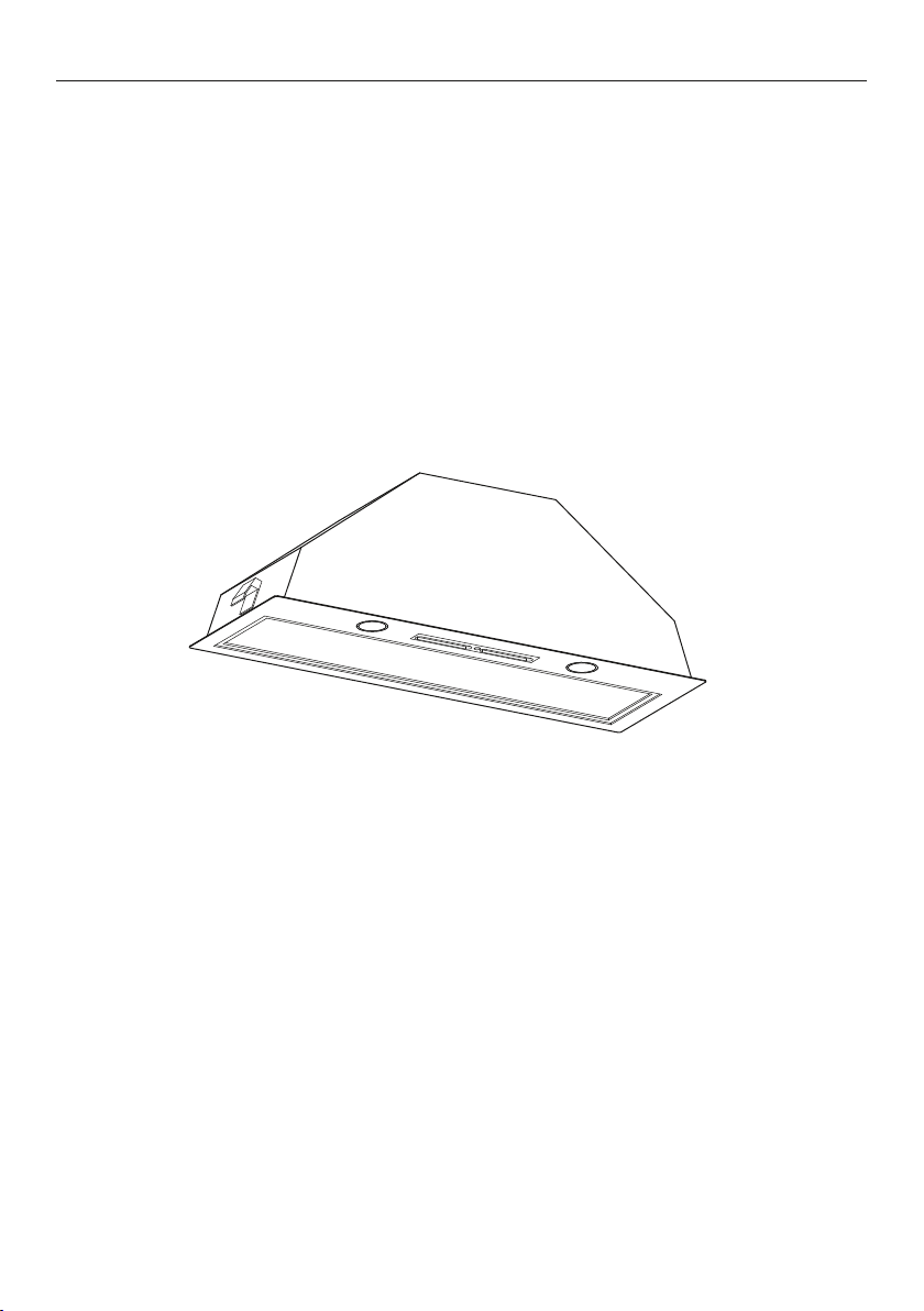
INTEGRATED INSERT
VENTILATION HOOD
HP24ILTX2 and HP36ILTX2 models
HOTTE DE VENTILATION
NCASTRABLE
E
Modéls HP24ILTX2 et HP36ILTX2
INSTALLATION GUIDE / USER GUIDE
GUIDE D’INSTALLATION / GUIDE D’UTILISATION
US CA
Page 2

English
Page 1 – 21
Français
Page 23
– 43
Page 3

CONTENTS
Introduction 3
Safety and warnings 4
Installation instructions 7
Operating instructions
Cleaning and maintenance
Parts and accessories
Limited Warranty
15
16
18
19
EN
Registration
To register your product visit our website: fisherpaykel.com/register
1
Page 4

Page 5
INTRODUCTION
Thank you for purchasing a Fisher & Paykel product.
Thousands of hours go into the design, engineering, testing and perfecting of each
Fisher & Paykel appliance. The care and attention given to creating these beautiful
products doesn’t stop once it has found its home with you.
This use and care manual will answer most of your questions about the set-up, use
and on-going maintenance of your Fisher & Paykel product; however if you require
further information about your product and its use please consult our website for
solutions and further contact information to discuss with a service representative.
To ensure you receive all relevant product updates and the best service possible,
please register your Fisher & Paykel products through our website.
EN
3
Page 6

SAFETY AND WARNINGS
!
WARNING!
Weight Hazard
The
ventilation hood is heavy. Please ensure adequate care is taken
wheninstalling the ventilation hood to prevent personal injury.
ventilation hood must be installed onto a solid wall, stud, beam
The
ortruss.
Product weight: 16lbs (7.1kg) HP24 / 20lbs (9.1kg) HP36.
!
WARNING!
Electric Shock Hazard
Always disconnect the appliance from the mains power supply before
carrying out any maintenance or repairs.
Installation work and electrical wiring must be done by qualified
person(s) in accordance with all applicable codes and standards,
including fire-rated construction.
Failure to do so can result in death, electric shock, fire or injury to
persons.
4
Page 7

SAFETY AND WARNINGS
IMPORTANT SAFETY INSTRUCTIONS
READ THE ENTIRE SET OF INSTRUCTIONS BEFORE INSTALLING OR USING
THIS APPLIANCE. Manuals can also be found on our website www.fisherpaykel.com.
CAUTION: For general ventilating use only. Do not use to exhaust hazardous
or explosive materials and vapors.
WARNING! To reduce the risk of fire, electric shock, or injury to persons, observe
thefollowing:
– Use this unit only in the manner intended by the manufacturer. If you have
questions, contact the manufacturer. For residential use only.
– Before servicing or cleaning unit, switch power off at service panel and lock
the service disconnecting means to prevent power from being switched on
accidentally. When the service disconnecting means cannot be locked, securely
fasten a prominent warning device, such as a tag, to the service panel.
– Installation work and electrical wiring must be done by qualified person(s)
in accordance with all applicable codes and standards, including fire-rated
construction.
– Sufficient air is needed for proper combustion and exhausting of gases through
the flue (chimney) of fuel burning equipment to prevent back drafting. Follow
the heating equipment manufacturer’s guideline and safety standards such as
those published by the National Fire Protection Association (NFPA), and the
American Society for Heating, Refrigeration and Air Conditioning Engineers
(ASHRAE), and the local code authorities.
– When cutting or drilling into wall or ceiling, do not damage electrical wiring
and other hidden utilities.
– Ducted fans must always be vented to the outdoors.
– This unit must be grounded.
CAUTION: To reduce risk of fire and to properly exhaust air, be sure to duct air
outside – Do not vent exhaust air into spaces within walls or ceilings or into attics,
crawl spaces, or garages.
WARNING: To reduce the risk of fire, use only metal ductwork.
WARNING: To reduce the risk of fire or electric shock, do not use this fan with
any solid-state speed control device.
WARNING: To reduce the risk of a range top grease fire:
– Never leave surface units unattended at high settings. Boilovers cause smoking
and greasy spillovers that may ignite. Heat oils slowly on low or medium
settings.
– Always turn hood ON when cooking at high heat or when flambéing food (ie
Crepes Suzette, Cherries Jubilee, Peppercorn Beef Flambé)
– Clean ventilating fans frequently. Grease should not be allowed to accumulate
on fan or filter.
– Use proper pan size. Always use cookware appropriate for the size of the
surface element.
EN
5
Page 8

SAFETY AND WARNINGS
WARNING: To reduce the risk of injury to persons in the event of a range top
grease fire, observe the following*:
– SMOTHER FLAMES with a close-fitting lid, cookie sheet, or metal tray, then
turn off the burner. BE CAREFUL TO PREVENT BURNS. If the flames do not go
out immediately, EVACUATE AND CALL THE FIRE DEPARTMENT.
– NEVER PICK UP A FLAMING PAN – You may be burned.
– DO NOT USE WATER, including wet dishcloths or towels – a violent steam
explosion will result.
– Use an extinguisher ONLY if:
– You know you have a Class ABC extinguisher, and you already know
how to operate it.
– The fire is small and contained in the area where it started.
– The fire department is being called.
– You can fight the fire with your back to an exit.
WARNING: Unplug or disconnect the appliance from the power supply before
servicing or cleaning.
READ AND SAVE THESE INSTRUCTIONS
* Based on “Kitchen Firesafety Tips” published by NFPA.
6
Page 9
I
INSTRUCTIONS D’INSTALLATION
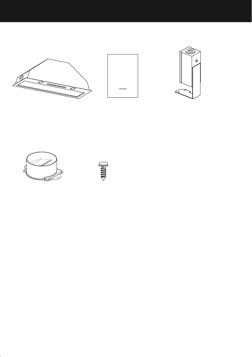
Contents of packaging
INSTALLATION INSTRUCTIONS
USER GUIDE
INSTRUCTIONS D’INSTALLATION
GUIDE D’UTILISATION
Integrated Perimeter Insert Ventilation Hood
Hotte de Ventilation Périmétrique Encastrable
HP24ILTX1 and HP36ILTX1 models
Modèles HP24ILTX1 et HP36ILTX1
US CA
EN
Ventilation hood
(1)
6” (152mm) diameter
Ducting adapter with
back draft damper
(1)
Installation instructions
User guide manual
(1)
3/8” (10mm)
Self tapping screw
(4)
Power connection box
(1)
7
Page 10
INSTALLATION INSTRUCTIONS
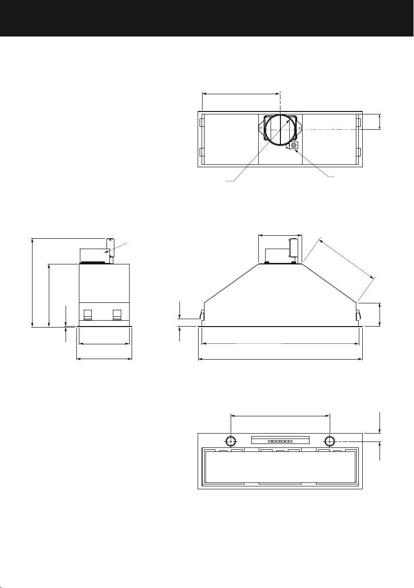
Product and cabinetry cutout dimensions
K
B
H
O
L
A
E
G
D
Ducting adapter
P
M
Ø
UL power
connection box
I
J
F
C
N
8
Page 11

INSTALLATION INSTRUCTIONS
HP24 HP36
PRODUCT DIMENSIONS
Overall height of product 133/4” (350) 13 3/4” (350)
A
Overall height of product (with
B
power connection box)
Overall width of product 207/8” (530) 3211/16” (830)
C
Overall depth of product 11” (280) 11” (280)
D
Thickness of flange 1/16” (2) 1/16” (2)
E
Width of chassis 193/8” (492) 313/16” (792)
F
Depth of chassis 101/16” (255) 101/16” (255)
G
Height of side of chassis 711/16” (195) 711/16” (195)
H
Width of top surface of chassis 113/4” (298) 113/4” (298)
I
Length of angled surface of chassis 67/8” (175) 11” (280)
J
Distance from center of ducting
K
outlet to back of chassis
Distance from center of ducting
L
outlet to side of chassis
Diameter of ducting outlet 6” (152) 6” (152)
M
Distance between center of lights 143/4” (375) 269/16” (675)
N
Distance from center of light to
O
front of product
CABINETRY CUTOUT DIMENSIONS
Overall width of cutout 1911/16” (500) 311/2” (800)
Overall depth of cutout 101/4” (260) 101/4” (260)
Base of brackets/clips to bottom of
P
chassis
min. 9/16” – max. 19/16”
inches (mm) inches (mm)
181/4” (463) 181/4” (463)
31/8“ (80) 31/8” (80)
95/8” (245) 159/16” (395)
19/16” (40) 1 9/16” (40)
(min. 15 – max. 40)
min. 9/16” – max. 19/16”
(min. 15 – max. 40)
EN
IMPORTANT!
Actual product dimensions may vary by ± 1/16”(2mm).
Please read the entire instructions before installing the ventilation hood.
9
Page 12

INSTALLATION INSTRUCTIONS
Height of ventilation hood
Q
MINIMUM CLEARANCES inches (mm)
Height top of cooktop to base
Q
of product
This ventilation hood must be installed no lower than the minimum height indicated
in the table above. Minimum installation height may be greater if required by the
cooktop manufacturer or safety and warning section of this user guide. Installation
at the minimum height will improve the efficiency of capturing cooking odors, grease
and smoke. Installation at the maximum height improves user ergonomics by offering
increased head room.
10
min. 26” – max. 30” (min 660 – max. 762)
Page 13

INSTALLATION INSTRUCTIONS
EN
WARNING!
To reduce the risk of fire, use only metal ductwork. Do not use flexible plastic ducting
CAUTION!
To reduce risk of fire and to properly exhaust air, be sure to duct air outside – do not
vent exhaust air into spaces within walls or ceilings or into attics, crawl spaces, or
garages.
Venting options
Attention should be given to ensure that any applicable regulations concerning the
discharge of exhaust air are fulfilled.
The ventilation hood can be installed to operate with the exhaust air ducted
externally from the kitchen.
Ducted
For ducted installation it is recommended that 6” (152mm) diameter, rigid or semi-rigid
ducting is used. This will require a 65/16” (160mm) (min) round hole in the ceiling or
wall. Care should be taken to position the hole correctly.
For optimal efficiency use the shortest and straightest duct route possible and use rigid
or semi-rigid ducting for reduced noise and increased airflow. Flexible metal ducting
should only be used as a last resort (ie in difficult installations) and if used ensure that it
is straight and smooth and extended as much as possible.
11
Page 14
INSTALLATION INSTRUCTIONS
WARNING!
This appliance is heavy and requires two persons for unpacking and installation
Installation work and electrical wiring must be done by qualified person(s) in
accordance with all applicable codes and standards.
Failure to install the screws or fixing device in accordance with these instructions
mayresult in electrical hazards
IMPORTANT!
Wear gloves to protect against sharp edges.
The manufacturer is not liable for any damage caused by not following these instructions.
Installation
Prepare for installation.
1
Before installing your ventilation hood:
Please read the instructions carefully.
Unpack the ventilation hood and check that all
functions are working.
Ensure that the voltage (V) and the frequency (Hz)
indicated on the serial plate match the voltage and
frequency at the installation site.
The stainless steel surfaces of the ventilation
hood are very easily damaged during installation
if grazed or knocked by tools. Please take care to
protect the surfaces during installation.
Protect the cooktop surface below with cardboard,
or the like, to prevent damage occurring whilst the
ventilation hood is being installed above.
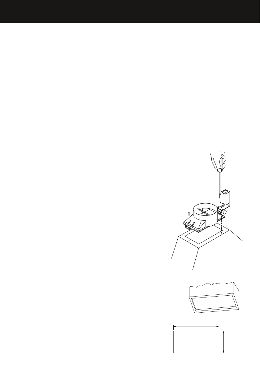
Attach ducting adapter and power connection box to
2
the ventilation hood
Place the ducting adapter onto the ventilation
hood and screw it in place using 3/8” (10mm)
screws.
Place the power connection box onto the
ventilation hood and screw it in place using 3/8”
(10mm) screws.
Follow wiring instructions described in the
‘Electrical connection’ section page14
Provide an opening on the underside of the cupboard
3
.
(see product and cabinetry cutout dimensions).
It is also recommended that the cupboard has a door
or service panel that can be easily opened to access
the power connection box
12
width
depth
Page 15

INSTALLATION INSTRUCTIONS
Remove the filters and face plate of the ventilation hood.
4
Images are for representation only, models may vary.
2
1
Lift the ventilation hood and fit through the opening of the cupboard till the spring
5
loaded brackets / clips hold the product in place.
EN
Secure ventilation hood while tightening the 4 brackets / clips.
6
x4
13
Page 16

INSTALLATION INSTRUCTIONS
WARNING!
Electrical wiring must be done by qualified person(s) in accordance with all applicable
codes and standards and the unit must be grounded.
Electrical connection
7
Run three wires, two for the power supply and one for the ground wire, from the
power connection box on the ventilation hood to a power connection point near
the installation.
Open the power connection box on the ventilation hood and secure the power
conductor with a cULus listed strain relief (not included).
Connect the power conductors to the conductors for the ventilation hood, black to
black and white to white.
Connect the grounding wire (green or bare) to the ground conductor (green) of the
ventilation hood power connection box.
Secure all the connections with cULus listed wire nuts.
Replace the power connection box cover.
EN
Gray 4 speed
Black 3 speed
Red 2 speed
Blue 1 speed
Brown (neutral)
14
Page 17

OPERATING INSTRUCTIONS
Touch control panel
CONTROL PANEL FEATURES
Light Turn the lights on or off.
Power ON/OFF Turn the ventilation hood on or off. The fan
automatically turns on to operate at level 1.
Reduce fan speed
Fan speed indicator The fan speed level icon illuminates red with the
Increase fan speed
Max Turn the fan on directly onto maximum fan speed.
Timer Turn the timer on. The fan speed light blinks and the
Note: for optimal performance it is recommended that the ventilation hood is
turned on before cooking is started.
Adjust the fan speed levels from 1 – 3 with 1 being
the lowest.
current fan speed.
Adjust the fan speed levels from 1 – 3 with 3 being
the highest.
fan will operate for 5 minutes at the current speed
and each decreasing speed before turning off (the
fan will stop and the light will go out).
To cancel the timer press the timer button once.
IMPORTANT!
The ventilation hood may stop working during an electrostatic discharge
(eg lightning). Switch off the electricity supply to the ventilation hood and
reconnect after one minute.
15
Page 18

CLEANING AND MAINTENANCE
WARNING!
Unplug or disconnect the appliance from the power supply before servicing
orcleaning.
When replacing the bulb, let the bulb cool, and assure that power to the ventilation
hood has been turned off. Use new bulbs according to that indicated on the
ventilation hood nameplate.
IMPORTANT!
Never use abrasive or oil based cleaners
Wear gloves to protect against sharp edges
Maintenance
The ventilation hood should be cleaned regularly
using a mild, liquid detergent and a clean soft cloth
to avoid a build-up of grease occurring. Avoid
the use of corrosive chemicals, abrasive cleaning
products, hard brushes and steel wool pads. Grease
deposits are corrosive which can cause damage to
your ventilation hood.
Note: in areas of high humidity or coastal
environments, cleaning should be carried out more
frequently.
EN
Aluminium filters
Depending on use, and at least once a month, the aluminium grease filters should be
removed and cleaned with hot soapy water or in a dishwasher.
If washed in a dishwasher, the filters should be placed in an upright position to prevent
food from falling on them.
After rinsing and drying, replace the filters.
Note: some discoloration of the frames may occur.
Removing the aluminium filters:
Open the stainless steel panel.
1
Pull the relative filter catch, tilting it downwards until it disengages from the supports.
2
Reverse these instructions when refitting the filters.
3
1
6
Page 19

CLEANING AND MAINTENANCE
WARNING!
When replacing the bulb, let the bulb cool, and assure that power to the ventilation
hood has been turned off. Use new bulbs according to that indicated on the
ventilation hood nameplate.
Light bulb replacement
Note: replacement bulbs are not covered by warranty.
Open the stainless steel panel.
1
Remove the aluminum filters.
2
Unscrew the light bulb.
3
Insert the replacement bulb into the lamp socket.
4
Replace the aluminium filters.
5
Close the stainless steel panel.
6
Bulb replacement
17
Page 20

PARTS AND ACCESSORIES
ITEM REFERENCE NUMBER
LED bulb
Aluminum filter 792429
792966
EN
1
8
Page 21

LIMITED WARRANTY
When you purchase any new Fisher & Paykel ventilation hood for personal or consumer
use you automatically receive a two year limited warranty covering parts and labor for
servicing within the 48 mainland United States, Hawaii, Washington DC and Canada. In
Alaska the limited warranty is the same except that you must pay to ship the product
to the service shop or the service technician’s travel to your home. Products for use
in Canada must be purchased through the Canadian distribution channel to ensure
regulatory compliance.
If the product is installed in a motor vehicle, boat or similar mobile facility, you receive
the same two year limited warranty, but you must bring the vehicle, boat or mobile
facility containing the product to the service shop at your expense or pay the service
technician’s travel to the location of the product.
There is no warranty for commercial purchase or use.
Fisher & Paykel undertakes to:
Repair without cost, with limited exceptions described herein, to the owner either for
material or labor any part of the product, the serial number of which appears on the
product, which is found to be defective. In Alaska, you must pay to ship the product
to the service shop or for the service technician’s travel to your home. If the product
is installed in a motor vehicle, boat or similar mobile facility, you must bring it to the
service shop at your expense or pay for the service technician’s travel to the location of
the product. If we are unable to repair a defective part of the product after a reasonable
number of attempts, at our option we may replace the part or the product, or we may
provide you a full refund of the purchase price of the product (not including installation
or other charges).
This warranty extends to the original purchaser and any succeeding owner of the
product during the term of the warranty for products purchased for ordinary singlefamily home use.
All service under this limited warranty shall be provided by Fisher & Paykel or its
Authorized Service Agent during normal business hours.
How long does this limited warranty last?
Our liability under this limited warranty expires TWO YEARS from the date of purchase
of the product by the first consumer.
Our liability under any implied warranties, including the implied warranty of
merchantability (an unwritten warranty that the product is fit for ordinary use) expires
TWO YEARS (or such longer period as required by applicable law) from the date of
purchase of the product by the first consumer. Some States do not allow limitations on
how long an implied warranty lasts, so this limit on implied warranties may not apply
to you. Fisher & Paykel will honor any warranty required by the law of the particular
country or state in which the product is sold.
19
Page 22

LIMITED WARRANTY
This limited warranty does not cover:
Service calls that are not related to any defect in the product. The cost of a service call
A
will be charged if the problem is not found to be a defect of the product. For example:
Correcting faulty installation of the product.
1
Instructing you how to use the product.
2
Replacing house fuses, resetting circuit breakers, correcting house wiring
3
or plumbing, or replacing light bulbs.
Correcting fault(s) caused by the user.
4
Changing the set-up of the product.
5
Unauthorized modifications of the product.
6
Noise or vibration that is considered normal, for example, fan sounds/noises
7
or user warning beeps.
Correcting damage caused by pests, for example, rats, cockroaches, etc
8
Replacement light bulbs.
9
Defects caused by factors other than:
B
Normal domestic use; or
1
Use in accordance with the product’s user guide.
2
Defects to the product caused by accident, neglect, misuse, fire, flood or ‘act of God’.
C
The cost of repairs carried out by non-authorized repairers or the cost of correcting
D
such unauthorized repairs.
Travel fees and associated charges incurred when the product is installed in a location
E
with limited or restricted access (eg airplane flights, ferry charges, isolated geographic
areas).
Normal recommended maintenance as set out in the product’s user guide.
f
Filter replacement except in the case of faulty parts or materials within the filter cartridge.
g
Damage (including water damage) caused by faulty installation, plumbing or wiring.
h
EN
This product has been designed for use in a normal domestic (residential) environment.
This product is not designed for commercial use (whatsoever). Any commercial use by
a customer will terminate this product’s limited warranty.
If you have an installation problem contact your dealer or installer. You are responsible
for providing adequate electrical, exhausting and other connection facilities.
Fisher & Paykel will not be responsible for consequential or incidental damages
(including, without limitation, the cost of repairing or replacing other property damaged
if the product is defective or any of your expenses caused if the product is defective).
Some States do not allow the exclusion or limitation of incidental or consequential
damages, so the above limitation or exclusion may not apply to you.
20
Page 23

LIMITED WARRANTY
How to get service
Please read your user guide. If you then have any questions about operating the
product, need the name of your local Fisher & Paykel Authorized Service Agent, or
believe the product is defective and wish service under this limited warranty, please
contact your dealer or call us at:
USA and Canada
TOLL FREE 1.888.9.FNP.USA (1.888.936.7872)
or use the link at: www.fisherpaykel.com/locator/servicer/
You may be required to provide reasonable proof of the date of purchase
of the product before the product will be serviced under this limited warranty.
No other warranties
This limited warranty is the complete and exclusive agreement between you and
Fisher & Paykel regarding any defect in the product and no other express warranty has
been made or will be made on behalf of Fisher & Paykel. None of our employees (or our
Authorized Service Agents) are authorized to make any addition or modification to
this limited warranty.
Warrantor: Fisher & Paykel Appliances, Inc.
If you need further help concerning this limited warranty, or need to make a claim under
this warranty, please call us at the above number, or write to:
Fisher & Paykel Appliances, Inc.
695 Town Center Drive, Suite 180
Costa Mesa
CA 92626
This limited warranty gives you specific legal rights, and you may also have other rights
which vary from country to country and from state to state.
Complete and keep for safe reference:
Model
Serial No.
Purchase Date
Purchaser
Dealer
City
State
Zip
Country
21
Page 24

Page 25

TABLE DES MATIÈRES
FR
Introduction
Consignes de sécurité et mises en garde
Instructions d’installation
Instructions d’utilisation
Nettoyage et entretien
Pièces et accessoires
Garantie limitée
25
26
29
37
38
40
41
Enregistrement
Pour enregistrer votre produit, visitez notre site Web: fisherpaykel.com/register
23
Page 26

Page 27

INTRODUCTION
Nous vous remercions d’avoir acheté ce produit Fisher&Paykel.
Plusieurs milliers d’heures sont consacrées à la conception, l’ingénierie, la mise à
l’essai et le perfectionnement de chaque appareil Fisher&Paykel. L’attention et le
soin portés à la création de ces superbes produits se poursuivent même après leur
livraison à votre domicile.
Ce manuel d’utilisation et d’entretien répond à la plupart des questions concernant
l’installation, l’utilisation et l’entretien de routine de votre produit Fisher&Paykel;
toutefois, si vous avez besoin d’informations supplémentaires au sujet de votre
produit et de son fonctionnement, veuillez visiter notre site Web pour obtenir des
solutions et des coordonnées permettant de communiquer avec un représentant de
service.
Pour vous assurer de recevoir toutes les mises à jour sur nos produits et un service de
la meilleure qualité possible, veuillez enregistrer vos produits Fisher&Paykel sur notre
site Web.
FR
25
Page 28

CONSIGNES DE SÉCURITÉ ET MISES EN GARDE
!
MISE EN GARDE!
Risque de poids excessif
La hotte de ventilation est lourde. Lors de l’installation de la hotte de
ventilation, veuillez vous assurer de porter une attention appropriée
afin d’éviter toute blessure.
La hotte de ventilation doit être installée sur un mur, un montant, une
poutre ou une ferme de charpente solide.
Poids du produit: 16lbs (7,1kg) HP24/ 20lbs (9,1kg) HP36.
!
MISE EN GARDE!
Risque de choc électrique
Déconnectez toujours l’appareil de l’alimentation électrique avant de
procéder à l’entretien ou à des réparations.
L’installation et le câblage électrique doivent être réalisés par une ou
plusieurs personne(s) qualifiée(s), en conformité avec tous les codes
et toutes les normes applicables, notamment en ce qui concerne les
constructions ignifuges.
Le fait de ne pas respecter ces consignes peut causer la mort, un choc
électrique, un incendie ou des blessures.
26
Page 29

CONSIGNES DE SÉCURITÉ ET MISES EN GARDE
CONSIGNES DE SÉCURITÉ IMPORTANTES
VEUILLEZ LIRE TOUTES CES CONSIGNES AVANT D’INSTALLER OU UTILISER
CET APPAREIL. Les manuels sont également disponibles sur notre site Web
www.fisherpaykel.com.
ATTENTION: Utiliser uniquement pour la ventilation générale. Ne pas utiliser pour
l’évacuation de matières ou de vapeurs dangereuses ou explosives.
MISE EN GARDE! Pour réduire les risques d’incendie, de choc électrique ou de
blessures, respectez ces consignes:
– Utilisez cet appareil uniquement de la manière prévue par le fabricant. Pour
toute question, communiquez avec le fabricant. Pour une utilisation résidentielle
uniquement.
– Avant de procéder à l’entretien ou au nettoyage de l’appareil, interrompez
l’alimentation au panneau électrique et verrouillez le dispositif d’interruption de
courant pour éviter que l’alimentation puisse être rétablie accidentellement. S’il
n’est pas possible de verrouiller le dispositif d’interruption de courant, apposez un
avertissement bien visible sur le panneau électrique, par exemple à l’aide d’une
étiquette.
– L’installation et le câblage électrique doivent être réalisés par une ou plusieurs
personne(s) qualifiée(s), en conformité avec tous les codes et toutes les normes
applicables, notamment en ce qui concerne les constructions ignifuges.
– Pour éviter le refoulement d’air, une quantité d’air suffisante est nécessaire
pour assurer une bonne combustion et l’évacuation des gaz à travers le carneau
(cheminée) de l’appareil. Suivez les consignes du fabricant de l’appareil de cuisson
ainsi que les normes de sécurité comme celles publiées par la National Fire
Protection Association (NFPA) et la American Society for Heating, Refrigeration
and Air Conditioning Engineers (ASHRAE), ainsi que les normes locales.
– Au moment de couper ou percer le mur ou le plafond, veillez à ne pas
endommager le câblage électrique ou les conduites qui y sont dissimulés.
– Les ventilateurs avec conduits doivent toujours évacuer l’air vers l’extérieur.
– Cet appareil doit être mis à la terre.
ATTENTION: Pour réduire les risques d’incendie et évacuer l’air adéquatement,
assurez-vous d’évacuer l’air vers l’extérieur– N’évacuez pas l’air dans les murs,
plafonds, greniers, vides sanitaires ou garages.
MISE EN GARDE: Pour réduire les risques d’incendie, utilisez uniquement des
conduits en métal.
MISE EN GARDE: Pour réduire les risques d’incendie ou de choc électrique, n’utilisez
pas ce ventilateur avec un dispositif de contrôle de vitesse à semi-conducteurs.
MISE EN GARDE: Pour réduire les risques de feu de graisse sur la cuisinière:
– Ne laissez jamais les éléments de surface sans surveillance lors de l’utilisation de
réglages élevés. Les débordements produisent de la fumée et des déversements
de matières grasses qui peuvent s’enflammer. Chauffez les huiles lentement, à
feu doux ou moyen.
– Allumez toujours la hotte lorsque vous cuisinez à feu vif ou faites flamber des
aliments (par ex.: crêpes Suzette, cerise jubilé, steak au poivre flambé).
– Nettoyez fréquemment les ventilateurs. Ne laissez jamais la graisse s’accumuler
sur le ventilateur ou le filtre.
– Utilisez des récipients de taille appropriée. Utilisez toujours des plats de cuisson
adaptés à la taille de l’élément de surface.
FR
27
Page 30

CONSIGNES DE SÉCURITÉ ET MISES EN GARDE
MISE EN GARDE: Pour réduire les risques de blessures en cas de feu de graisse sur la
cuisinière, respectez ces consignes*:
– ÉTOUFFEZ LES FLAMMES avec un couvercle hermétique, une plaque à biscuits
ou un plateau métallique, puis éteignez le brûleur. FAITES ATTENTION DE NE
PAS VOUS BRÛLER. Si les flammes ne s’éteignent pas immédiatement, ÉVACUEZ
LA PIÈCE ET APPELEZ LE SERVICE D’INCENDIE.
– NE PRENEZ JAMAIS UN RÉCIPIENT QUI EST EN FLAMMES– vous pourriez vous
brûler.
– N’UTILISEZ PAS DE L’EAU, ni de linges ou serviettes humides, car cela pourrait
causer une violente explosion de vapeur.
– Utilisez un extincteur UNIQUEMENT si:
– Vous savez qu’il s’agit d’un extincteur de classe ABC et vous savez vous en
servir.
– Le feu est peu important et localisé dans la zone où il a commencé.
– Vous avez appelé le service d’incendie.
– Vous pouvez combattre le feu en ayant le dos tourné vers une sortie.
MISE EN GARDE: Débranchez ou déconnectez l’appareil de l’alimentation électrique
avant de procéder à l’entretien ou au nettoyage.
LISEZ ET CONSERVEZ CES INSTRUCTIONS
* Tirés des conseils sur la sécurité en matière d’incendie de cuisine de la NFPA.
28
Page 31

I
INSTRUCTIONS D’INSTALLATION
Contenu de l’emballage
INSTALLATION INSTRUCTIONS
USER GUIDE
INSTRUCTIONS D’INSTALLATION
GUIDE D’UTILISATION
Integrated Perimeter Insert Ventilation Hood
Hotte de Ventilation Périmétrique Encastrable
HP24ILTX1 and HP36ILTX1 models
Modèles HP24ILTX1 et HP36ILTX1
US CA
FR
Hotte de ventilation
(1)
Adaptateur de conduit
de 6po (152mm) de
diamètre avec clapet
anti-refoulement d’air
(1)
Instructions d’installation
Guide d’utilisation
(1)
Vis autotaraudeuses
de 3/8po (10mm)
(4)
Boîtier de raccordement
d’alimentation
(1)
29
Page 32

INSTRUCTIONS D’INSTALLATION
K
B
H
O
Dimensions du produit et de l’ouverture dans l’armoire
L
A
E
G
D
Adaptateur de conduit
P
M
Ø
Boîtier de
raccordement
d’alimentation UL
I
J
F
C
N
3
0
Page 33

INSTRUCTIONS D’INSTALLATION
HP24 HP36
DIMENSIONS DU PRODUIT
Hauteur hors tout du produit 133/4po (350) 133/4po (350)
A
Hauteur hors tout du produit
B
(avec boîtier de raccordement
d’alimentation)
Largeur hors tout du produit 207/8po (530) 3211/16po (830)
C
Profondeur hors tout du produit 11po (280) 11po (280)
D
Épaisseur de la bride 1/16po (2) 1/16po (2)
E
Largeur du châssis 193/8po (492) 313/16po (792)
F
Profondeur du châssis 101/16po (255) 101/16po (255)
G
Hauteur du côté du châssis 711/16po (195) 711/16po (195)
H
Largeur de la surface supérieure du
I
châssis
Longueur de la surface inclinée du
J
châssis
Distance entre le centre de la sortie
K
de conduit et l’arrière du châssis
Distance entre le centre de la sortie
L
de conduit et le côté du châssis
Diamètre de la sortie de conduit 6po (152) 6po (152)
M
Distance entre le centre des lampes 143/4po (375) 269/16po (675)
N
Distance entre le centre de la lampe
O
et l’avant du produit
DIMENSIONS DE L’OUVERTURE DANS L’ARMOIRE
Largeur hors tout de l’ouverture 1911/16po (500) 311/2po (800)
Profondeur hors tout de l’ouverture 101/4po (260) 101/4po (260)
De la base des supports/clips
P
jusqu’au dessous du châssis
min. 9/16po – max. 19/16po
pouces (mm) pouces (mm)
181/4” (463) 181/4” (463)
113/4po (298) 113/4po (298)
67/8po (175) 11po (280)
31/8po (80) 31/8po (80)
95/8po (245) 159/16po (395)
19/16po (40) 1 9/16po (40)
(min. 15 – max. 40)
min. 9/16po – max. 19/16po
(min. 15 – max. 40)
FR
IMPORTANT!
Les dimensions réelles du produit peuvent varier de ± 1/16po (2mm).
Veuillez lire toutes les instructions avant d’installer la hotte de ventilation.
3
1
Page 34

INSTRUCTIONS D’INSTALLATION
Hauteur de la hotte de ventilation
Q
DÉGAGEMENT MINIMAL pouces (mm)
Hauteur du dessus de la surface
Q
de cuisson à la base du produit
La hotte de ventilation doit être installée en respectant le dégagement minimal et
maximal indiqués dans le tableau ci-dessus. La hauteur d’installation minimale peut être
augmentée si nécessaire suivant les instructions du fabricant de votre surface de cuisson
ou les consignes de sécurité et mises en garde décrites dans ce manuel. Une installation
à la hauteur inférieure améliore l’efficacité de l’appareil pour l’élimination des odeurs,
de la graisse et de la fumée de cuisson. Une installation à la hauteur maximale améliore
l’ergonomie pour l’utilisateur avec plus de dégagement pour la tête.
3
2
min. 26po – max. 30po (min 660 – max. 762)
Page 35

INSTRUCTIONS D’INSTALLATION
MISE EN GARDE!
Pour réduire les risques d’incendie, utilisez uniquement des conduits en métal.
N’utilisez pas de conduits en plastique flexible.
ATTENTION!
Pour réduire les risques d’incendie et évacuer l’air adéquatement, assurez-vous
d’évacuer l’air vers l’extérieur– n’évacuez pas l’air dans les murs, plafonds, greniers,
vides sanitaires ou garages.
Options pour l’évacuation
Veuillez porter une attention particulière à assurer la conformité à toutes les
réglementations relatives à l’évacuation de l’air.
La hotte de ventilation peut être installée de manière à fonctionner en évacuant l’air à
l’extérieur de la cuisine par un conduit.
Avec conduit
Pour l’installation avec conduit, il est recommandé d’utiliser un conduit rigide ou semirigide de 6po (152mm) de diamètre. Un trou circulaire de 6⁄po (160mm) (min.)
est alors requis dans le plafond ou le mur. Veuillez vous assurer de positionner le trou
correctement.
Pour une efficacité optimale, utilisez le trajet de conduit le plus court et le plus droit
possible, ainsi qu’un conduit rigide ou semi-rigide afin d’atténuer le bruit et augmenter
la circulation d’air. Un conduit en métal flexible doit uniquement être utilisé en dernier
recours (dans des installations difficiles); en pareil cas, veillez à ce qu’il soit aussi droit,
lisse et allongé que possible.
FR
3
3
Page 36

INSTRUCTIONS D’INSTALLATION
MISE EN GARDE!
Cet appareil est lourd. Il doit être déballé et installé par deux personnes.
L’installation et le câblage électrique doivent être réalisés par une ou plusieurs
personne(s) qualifiée(s), en conformité avec tous les codes et toutes les normes
applicables.
Le fait de ne pas installer les vis ou le dispositif de fixation conformément à ces
instructions peut entraîner des risques de choc électrique.
IMPORTANT!
Portez des gants pour vous protéger des rebords tranchants.
Le fabricant n’est pas responsable des dommages résultant du non-respect de ces instructions.
Installation
Préparez-vous pour l’installation.
1
Avant d’installer votre hotte de ventilation:
Veuillez lire attentivement les instructions.
Déballez la hotte de ventilation et vérifiez que toutes les
fonctions sont opérationnelles.
Assurez-vous que la tension (V) et la fréquence (Hz)
indiquées sur la plaque signalétique correspondent à la
tension et la fréquence sur le site d’installation.
Les surfaces en acier inoxydable de la hotte de ventilation
peuvent être très facilement endommagées pendant
l’installation en cas de frottement ou contact avec un
outil. Veuillez vous assurer de protéger les surfaces
pendant l’installation.
Protégez la surface de cuisson située sous l’appareil
avec du carton ou un matériau semblable pour éviter
de l’endommager pendant l’installation de la hotte
de ventilation.
Installez l’adaptateur de conduit et le boîtier de
2
raccordement d’alimentation à la hotte de ventilation
Placez l’adaptateur de conduit sur la hotte de
ventilation, puis vissez-le en place à l’aide des vis
de 3/8po (10mm).
Placez le boîtier de raccordement d’alimentation
sur la hotte de ventilation, puis vissez-le en place à
l’aide des vis de 3/8po (10mm).
Suivez les instructions de câblage présentées dans
la section ‘Raccordement électrique’ à la page36.
Prévoyez une ouverture dans le dessous de l’armoire
3
(voir les dimensions du produit et de l’ouverture dans
l’armoire).
Il est recommandé d’avoir un accès au boîtier de
raccordement soit avec une porte d’armoire ou un
panneau de service facilement détachable.
34
largeur
profondeur
Page 37

INSTRUCTIONS D’INSTALLATION
Retirez les filtres et la plaque frontale de la hotte de ventilation.
4
Les images sont à titre indicatif seulement, les modèles peuvent varier
2
1
FR
Soulevez la hotte de
5
les à supports/ clips
Fixez la hotte de ventilation en serrant les 4supports/ clips.
6
ventilation et insérez-la dans l’ouverture de l’armoire jusqu’à ce que
ressort maintiennent le produit en place.
x4
35
Page 38

INSTRUCTIONS D’INSTALLATION
MISE EN GARDE!
Le câblage électrique doit être réalisé par une ou plusieurs personne(s) qualifiée(s),
en conformité avec tous les codes et toutes les normes applicables, en veillant à ce
que l’appareil soit mis à la terre.
Raccordement électrique
7
Acheminez trois fils, deux pour l’alimentation et un pour la mise à la terre, du
boîtier de raccordement d’alimentation sur la hotte de ventilation à un point de
raccordement d’alimentation situé près de l’emplacement d’installation.
Ouvrez le boîtier de raccordement d’alimentation sur la hotte de ventilation et fixez le
conducteur d’alimentation à l’aide d’un serre-câble homologué cULus.
Connectez les conducteurs d’alimentation aux conducteurs de la hotte de ventilation,
le noir au noir et le blanc au blanc.
Connectez le fil de mise à la terre (vert ou dénudé) au conducteur de mise à la terre
(vert) du boîtier de raccordement d’alimentation de la hotte de ventilation.
Fixez tous les raccordements à l’aide de capuchons de connexion homologués cULus.
Réinstallez le couvercle du boîtier de raccordement d’alimentation.
FR
Gris 4vitesses
Noir 3vitesses
Rouge 2vitesses
Bleu 1vitesse
Brun (neutre)
6
3
Page 39

INSTRUCTIONS D’UTILISATION
Panneau de commande tactile
FONCTIONNALITÉS DU PANNEAU DE COMMANDE
Lampes Permet d’allumer ou éteindre les lampes.
Mise en MARCHE/
ARRÊT
Réduction de
la vitesse du
ventilateur
Indicateur de
vitesse du
ventilateur
Augmentation
de la vitesse du
ventilateur
Vitesse maximale Permet de mettre en marche le ventilateur
Minuterie Permet d’activer la minuterie. Le témoin de
Remarque: pour une efficacité optimale, il est recommandé de mettre en marche la
hotte de ventilation avant de débuter la cuisson.
Permet de mettre en marche ou d’arrêter la hotte de
ventilation. Le ventilateur s’active automatiquement
pour fonctionner au niveau1.
Permet de régler la vitesse du ventilateur à des
niveaux de 1 à 3, 1 étant le réglage le moins rapide.
L’icône de niveau de vitesse du ventilateur s’allume
en rouge en indiquant la vitesse actuelle.
Permet de régler la vitesse du ventilateur à des
niveaux de 1 à 3, 3 étant le réglage le plus rapide.
directement à la vitesse de ventilateur maximale.
vitesse du ventilateur clignotera et le ventilateur
fonctionnera pendant 5minutes à la vitesse actuelle,
puis à chacune des vitesses inférieures jusqu’à l’arrêt
(le ventilateur s’arrêtera et le témoin s’éteindra).
Pour annuler la minuterie, appuyez une fois sur la
touche de minuterie.
IMPORTANT!
La hotte de ventilation pourrait cesser de fonctionner en cas de décharge
électrostatique (par ex.: éclair). Interrompez l’alimentation électrique à la hotte de
ventilation, puis rétablissez-la après une minute.
37
Page 40

NETTOYAGE ET ENTRETIEN
MISE EN GARDE!
Débranchez ou déconnectez l’appareil de l’alimentation électrique avant de procéder
à l’entretien ou au nettoyage.
Avant de remplacer une ampoule, laissez l’ampoule refroidir et assurez-vous que
l’alimentation de la hotte de ventilation est interrompue. Utilisez de nouvelles
ampoules correspondant aux valeurs indiquées sur la plaque signalétique de la hotte
de ventilation.
IMPORTANT!
N’utilisez jamais de nettoyants abrasifs ou à base d’huile.
Portez des gants pour vous protéger des rebords tranchants.
Entretien
La hotte de ventilation doit être nettoyée
régulièrement à l’aide d’un détergent liquide doux et
d’un chiffon doux et propre pour éviter l’accumulation
de dépôts de graisse. Évitez d’utiliser des produits
chimiques corrosifs, des produits de nettoyage
abrasifs, des brosses dures et des tampons de laine
d’acier. Les dépôts de graisse sont corrosifs et
peuvent endommager votre hotte de ventilation.
Remarque: dans les régions où l’humidité est élevée
ou les environnements côtiers, le nettoyage doit être
effectué plus fréquemment.
FR
Filtres en aluminium
Selon la fréquence d’utilisation, et au moins une fois par mois, vous devez retirer les
filtres en aluminium et les nettoyer avec de l’eau savonneuse et chaude ou dans un lavevaisselle.
Si vous les lavez au lave-vaisselle, vous devez placer les filtres dans une position
verticale pour éviter que des aliments se déposent sur ceux-ci.
Après le rinçage et le séchage, réinstallez les filtres.
Remarque: une certaine décoloration pourrait se produire sur les cadres.
Retrait des filtres en aluminium:
Ouvrez le panneau en acier inoxydable.
1
Tirez sur le loquet du filtre afin de l’incliner vers le bas jusqu’à ce qu’il se désengage des
2
supports.
Suivez ces instructions dans l’ordre inverse pour réinstaller les filtres.
3
8
3
Page 41

NETTOYAGE ET ENTRETIEN
MISE EN GARDE!
Avant de remplacer une ampoule, laissez l’ampoule refroidir et assurez-vous que
l’alimentation de la hotte de ventilation est interrompue. Utilisez de nouvelles
ampoules correspondant aux valeurs indiquées sur la plaque signalétique de la hotte
de ventilation.
Remplacement de l’ampoule
Remarque: les ampoules de rechange ne sont pas couvertes par la garantie.
Ouvrez le panneau en acier inoxydable.
1
Retirez les filtres en aluminium.
2
Dévissez l’ampoule.
3
Insérez l’ampoule de rechange dans la douille de lampe.
4
Réinstallez les filtres en aluminium.
5
Fermez le panneau en acier inoxydable.
6
39
Remplacement de l’ampoule
Page 42

PIÈCES ET ACCESSOIRES
ARTICLE NUMÉRO DE RÉFÉRENCE
Ampoule à LED
Filtre en aluminium 792429
792966
FR
0
4
Page 43

GARANTIE LIMITÉE
Lorsque vous achetez une nouvelle hotte de ventilation Fisher&Paykel destinée à un
usage personnel ou celui d’un consommateur, vous bénéficiez automatiquement d’une
garantie limitée de deux ans s’appliquant aux pièces et à la main-d’œuvre pour le service
dans les 48États continentaux des États-Unis, à Hawaï, à Washington DC et au Canada.
Les clients de l’Alaska bénéficient de la même garantie limitée, mais ils doivent payer les
frais nécessaires pour la livraison du produit à l’atelier de réparation ou le déplacement
d’un technicien à leur domicile. Les produits pour l’utilisation au Canada doivent être
achetés auprès du réseau de distribution canadien pour assurer la conformité aux
réglementations.
Si le produit est installé dans un véhicule à moteur, un bateau ou une installation mobile
similaire, vous bénéficiez de la même garantie limitée de deux ans, mais vous devez
apporter à vos frais le véhicule, le bateau ou l’installation mobile contenant le produit à
l’atelier de réparation ou payer le déplacement du technicien d’entretien à l’endroit où se
trouve le produit.
Aucune garantie n’est offerte pour un achat ou une utilisation à des fins commerciales.
Fisher&Paykel s’engage à:
Réparer sans frais encouru par le propriétaire pour le matériel ou la main-d’œuvre, sauf
pour certaines exceptions décrites aux présentes, toute pièce s’avérant défectueuse
du produit dont le numéro de série figure sur celui-ci. Les clients de l’Alaska doivent
payer les frais nécessaires pour la livraison du produit à l’atelier de réparation ou le
déplacement d’un technicien à leur domicile. Si le produit est installé dans un véhicule à
moteur, un bateau ou une installation mobile similaire, vous devez l’apporter à l’atelier de
réparation à vos frais ou payer le déplacement d’un technicien à l’endroit où se trouve
le produit. Si nous ne parvenons pas à réparer une pièce défectueuse du produit après
un nombre de tentatives raisonnable, nous pourrons à notre discrétion remplacer la
pièce ou le produit, ou vous offrir un remboursement complet du prix d’achat du produit
(excluant les frais d’installation ou autres coûts).
Cette garantie est valable pour le propriétaire initial et tout propriétaire subséquent du
produit pendant la durée de la garantie, s’il est acheté pour une utilisation normale dans
un domicile familial simple.
Toutes les réparations couvertes par cette garantie limitée doivent être effectuées par
Fisher&Paykel ou un agent de service autorisé pendant les heures d’ouverture normales.
Quelle est la durée de cette garantie limitée?
Notre responsabilité en vertu de cette garantie limitée expire DEUX ANS à partir de la
date d’achat du produit par le premier acheteur.
Notre responsabilité en vertu de toute garantie implicite, incluant la garantie implicite de
qualité marchande (la garantie non écrite que le produit est adéquat pour une utilisation
normale) est limitée à DEUX ANS (ou une période plus longue, si cela est exigé par la loi
en vigueur) à partir de la date d’achat du produit par le premier acheteur. Certains États
ne permettent pas les limitations de durée de la garantie implicite. Par conséquent, cette
limitation pourrait ne pas s’appliquer à vous. Fisher&Paykel honorera toute garantie
prévue par la loi dans le pays ou l’État où le produit est vendu.
4
1
Page 44

GARANTIE LIMITÉE
Cette garantie limitée ne couvre pas:
Les demandes de réparation pour tout problème non lié à une défectuosité du produit.
A
Le coût de la demande de réparation sera facturé s’il se trouve que le problème n’est
pas dû à une défectuosité du produit. Par exemple:
Correction d’une installation inappropriée du produit.
1
Explication du fonctionnement du produit.
2
Remplacement des fusibles du domicile, réarmement des disjoncteurs, réparation du
3
câblage électrique ou de la plomberie du domicile et remplacement des ampoules.
Réparation des défectuosités causées par l’utilisateur.
4
Modification de la configuration du produit.
5
Modifications non autorisées du produit.
6
Bruits ou vibrations considérés normaux, par exemple, des sons/bruits de ventilateur
7
ou bips d’avertissement.
Réparation des dommages causés par des animaux nuisibles, par exemple, des rats,
8
cafards, etc.
Remplacement des ampoules.
9
Défectuosités du produit causées par des facteurs autres que:
B
Utilisation domestique normale; ou
1
Utilisation en conformité avec le guide d’utilisation du produit.
2
Défectuosités du produit causées par un accident, la négligence, une utilisation
C
inappropriée, un incendie, une inondation ou une catastrophe naturelle.
Les frais des réparations effectuées par des réparateurs non autorisés ou les frais
D
associés à la correction de telles réparations non autorisées.
Les frais de déplacement et frais associés encourus lorsque le produit est installé dans
E
un endroit où l’accès est limité ou restreint (par exemple, frais d’avion et de traversier,
régions géographiques isolées).
L’entretien normal recommandé dans le guide d’utilisation du produit.
f
Le remplacement du filtre, sauf en présence de pièces ou matériaux défectueux à
g
l’intérieur de la cartouche du filtre.
Dommages (y compris les dommages causés par l’eau) provoqués par une installation,
h
un raccordement de plomberie ou un câblage incorrect.
FR
Ce produit a été conçu pour une utilisation dans un environnement domestique normal
(résidentiel). Il n’est pas conçu pour une utilisation commerciale (de quelque nature que
ce soit). Toute utilisation commerciale entraînera l’annulation de la garantie limitée de ce
produit.
En cas de problème d’installation, communiquez avec votre détaillant ou installateur.
Il est de votre responsabilité d’assurer des installations électriques, d’évacuation et de
raccordement appropriées.
Fisher&Paykel ne sera responsable d’aucun dommage indirect ou accessoire (y
compris, sans limitation, le coût de réparation ou de remplacement d’autres biens
endommagés si le produit est défectueux ou tout autre coût encouru si le produit est
défectueux). Certaines juridictions ne permettent pas l’exclusion ou la limitation de la
responsabilité pour les dommages indirects ou accessoires; par conséquent, l’exclusion
ou la limitation ci-dessus pourrait ne pas s’appliquer à vous.
2
4
Page 45

GARANTIE LIMITÉE
Comment obtenir une réparation
Veuillez lire votre guide d’utilisation. Si vous avez des questions concernant l’utilisation
du produit, souhaitez trouver le nom d’un agent de service autorisé Fisher&Paykel
local ou pensez que le produit est défectueux et désirez le faire réparer dans le cadre
de cette garantie limitée, veuillez communiquer avec votre détaillant ou nous appeler au
numéro suivant:
États-Unis et Canada
SANS FRAIS 1.888.9.FNP.USA (1.888.936.7872)
ou utilisez le lien sur cette page: www.fisherpaykel.com/locator/servicer/
Il pourrait vous être demandé de fournir une preuve valable de la date d’achat du
produit avant que la réparation soit effectuée dans le cadre de cette garantie limitée.
Aucune autre garantie
Cette garantie limitée constitue la totalité de l’accord exclusif existant entre l’acheteur
et Fisher&Paykel relativement à toute défectuosité de ce produit; aucune autre
garantie expresse n’est offerte ou ne sera offerte au nom de Fisher&Paykel. Aucun de
nos employés (ou agents de service autorisés) n’est autorisé à effectuer des ajouts ou
apporter des modifications à cette garantie limitée.
Garant: Fisher&Paykel Appliances, Inc.
Si vous avez besoin d’aide au sujet de cette garantie limitée ou devez faire une demande
en vertu de cette garantie, veuillez nous appeler au numéro ci-dessus ou nous écrire à
l’adresse suivante:
Fisher&Paykel Appliances, Inc.
695 Town Center Drive, Suite 180
Costa Mesa
CA 92626
Cette garantie limitée vous donne des droits juridiques spécifiques auxquels peuvent
s’ajouter d’autres droits qui varient d’un pays et d’une juridiction à l’autre.
Remplir et conserver pour référence ultérieure:
Modèle
N° de série
Date d’achat
Acheteur
Détaillant
Ville
État/Province
Code postal
Pays
4
3
Page 46

Page 47

Page 48

FISHERPAYKEL.COM
© Fisher & Paykel Appliances 2020. All rights reserved.
The models shown in this guide may not be available in all markets and are
The product specifications in this guide apply to the specific products and
models described at the date of issue. Under our policy of continuous product
improvement, these specifications may change at any time.
For current details about model and specification availability in your country,
please go to our website or contact your local Fisher&Paykel dealer.
© Fisher&Paykel Appliances 2020. Tous droits réservés.
Les modèles illustrés dans ce guide peuvent ne pas être disponibles dans tous
les pays et sont sujets à modifications sans préavis.
Les caractéristiques de produit présentées dans ce guide s’appliquent aux
modèles et produits spécifiques qui y sont décrits à la date de publication. Dans
le cadre de notre politique d’amélioration en permanence de nos produits, ces
caractéristiques peuvent être modifiées à tout moment.
Pour les plus récentes informations sur la disponibilité des modèles et des
caractéristiques dans votre pays, veuillez visiter notre site Web ou contacter
subject to change at any time.
votre détaillant Fisher&Paykel local.
866053A 6.20
 Loading...