

Page 1

CLASSIC RANGEHOOD
HC90PCTX1, HC90PCB1, HC90PCW1 and
HC90PCR1 models
INSTALLATION GUIDE
NZ AU
Page 2
SAFETY AND WARNINGS
!
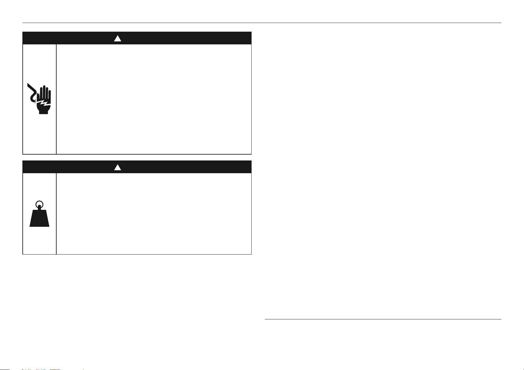
WARNING!
Electric Shock Hazard
Failure to follow this advice may result in
electric shock or death.
• This appliance is equipped with a three-prong or
four-prong grounding plug for your protection
against shock hazard and should be plugged
directly into a properly grounded power outlet.
• Never remove the grounding plug or use with
a 2 prong adapter.
• Do not immerse cord or plugs in water or
other liquid.
!
WARNING!
Weight Hazard
Failure to follow this advice may result in
personal injury
• The appliance is heavy. Please ensure adequate
care is taken when installing the appliance to
prevent personal injury. The appliance must be
installed onto a solid wall, stud, beam or truss.
• Product weight: 23kg
WARNING!
When using this appliance always exercise basic safety precautions includingthe following:
z
Please read the entire set of instructions before installing or using this appliance.
z
Please make this information available to the person installing the appliance – doing so
could reduce your installation costs.
z
Always switch the power off prior to installation, servicing or cleaning of the appliance.
z
This appliance must be installed and connected to the mains power supply only by a
suitably qualified person according to these installation instructions and in compliance with
any applicable local building and electricity regulations. Failure to install the appliance
correctly could invalidate any warranty or liability claims.
z
To comply with electrical safety regulations, the appliance must be plugged into a socket
near the appliance. The socket must be accessible, or have an accessible isolating switch,
to enable the end user to isolate the appliance from the power for the purpose of internal
cleaning or maintenance.
z
A power outlet should be within 750mm of the motor assembly and can either be on the
wall, behind the chimney or in the ceiling.
z
If the supply cord of this equipment is damaged, it must only be replaced by the
manufacturer, its service agent or similarly qualified person in order to avoid a hazard.
z
Ducting accessories are not supplied. All ducting must comply with local requirements and
building codes.
z
Attention should be given to ensure that any applicable regulations concerning the
discharge of exhaust air are fulfilled.
z
Before connecting any pipes, consult municipal ordinances to ensure that any applicable
regulations concerning the discharge of exhaust air are adhered to and request permission
from the person in charge of the building.
z
Exhaust air must not be discharged into an existing flue that is used for exhausting fumes
from appliances burning gas or other fuels.
z
There shall be adequate ventilation of the room when the rangehood is used at the same
time as appliances burning gas or other fuels.
z
The minimum distance between the supporting surface for cooking vessels on the cooktop
and the lowest part of the appliance shall be 600mm or 650mm if installed over a
gas cooktop.
z
Stainless steel or powdercoat is very easily damaged during installation if abraded or
knocked by tools. It is recommended to protect the top of the appliance with cardboard or
polystyrene during the installation to minimise the risk of damage occurring.
z
To reduce the risk of damage occurring to the cooktop, it is recommended that the surface
of the cooktop is protected with cardboard or a similar object during installation of
the rangehood.
SAVE THESE INSTRUCTIONS
The models shown in this installation guide may not be available in all markets and are subject to
change at any time. For current details about model and specification availability in your country,
please go to our website www.fisherpaykel.com or contact your local Fisher&Paykel dealer.
2
Page 3
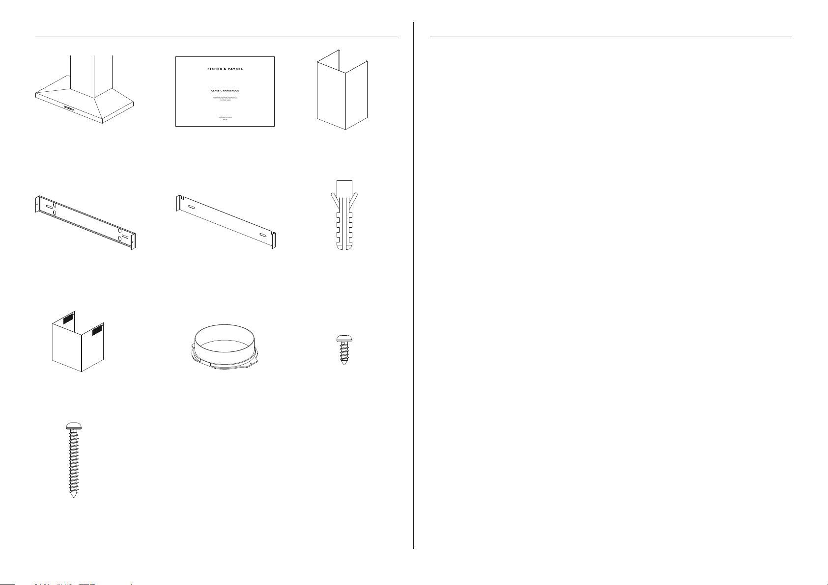
PARTS SUPPLIED
Rangehood hood (1) Chimney (1)
Installation guide (1)
PRIOR TO INSTALLATION
Fisher & Paykel is not liable for any damage caused by not following these instructions.
z
Please read the instructions carefully.
z
Unpack the rangehood.
z
Ensure the voltage (V) and the frequency (Hz) indicated on the rating plate match
thevoltage and frequency of the installation site.
z
Check all functions are working.
z
Check that the area behind the installation surface to be drilled is clear of any electrical
cables or pipes etc.
z
The rangehood surfaces can be damaged during installation if grazed or knocked
bytools. Please take care to protect the surfaces during installation.
z
Protect the cooktop surface with cardboard, or the like, to prevent damage
occurringwhilst the rangehood is being installed above.
z
Temporarily mark the height of the bottom of the rangehood and the centre of the
cooktop on the wall according to the information given in the 'Installation height' section.
z
The wall used for mounting the rangehood should have sufficient strength and a
flatsurface.
Upper chimney bracket (1) Chimney bracket (1)
Upper chimney (1) 150mm diameter ducting
adapter with damper (1)
30mm self-tapping
screw (10)
Expansion
plug (10)
10mm self-tapping
screw (4)
3
Page 4
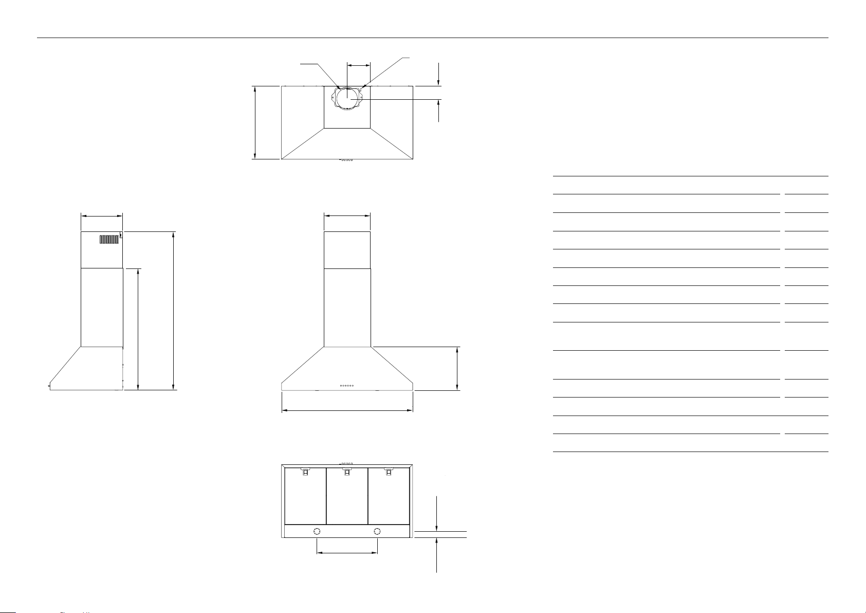
PRODUCT DIMENSIONS
g
b
A
d
j
PLAN
f
i
Power cord location
h
PRODUCT DIMENSIONS MM
A Maximum overall height of product 975
B Minimum overall height of product 636
C Overall width of product 898
D Overall depth of product 500
E Height of hood 298
F Width of chimney 320
G Depth of chimney 290
H Distance from centre of ducting outlet to back
of product 95
e
of chimney
I Distance from centre of ducting outlet to side
160
J Diameter of ducting outlet 150
PROFILE
c
FRONT
K Distance between centre oflights 413
L Distance between lights toback of product 42
Length of power cord 800
Actual product dimensions may vary by ± 2 mm.
l
k
BOTTOM
4
Page 5

INSTALLATION HEIGHT
ATTACHMENT DIMENSIONS
A
B
HEIGHT DIMENSIONS MM
H
G
Upper chimney bracket
attachment points
E
Chimney bracket
attachment points
C
F
D
B
Upper rangehood hood
attachment points
Lower rangehood
attachment points
A
ATTACHMENT DIMENSIONS MM
A Ducted installation
z
Minimum height
z
Maximum height
636
975
Recirculation
z
Minimum height
z
Maximum height
676
975
B Height from top of cooktop to base of product 650 – 750
This rangehood must be installed no lower than the minimum height indicated in the table
above. Minimum installation height may be greater if required by the cooktop, refer to your
cooktop installation instructions.
Installation at the minimum height will improve the efficiency of capturing cooking odours,
grease and smoke. Installation above the minimum height is the users preference, it is not
recommended to install above the maximum height indicated in the table above.
A Lower rangehood attachment point width 508
B Lower rangehood attachment point height 47
C Upper rangehood attachment point width 250
D Upper rangehood attachment point height 294
E Chimney bracket attachment point width 250
F Chimney bracket attachment point height 596
G Upper chimney bracket attachment point width 250
H Upper chimney bracket attachment point height 25
5
Page 6

VENTING OPTIONS
Attention should be given to ensure that any applicable regulations concerning the discharge of exhaust air are fulfilled.
The rangehood can be installed to operate with the exhaust air ducted externally from the kitchen, or installed to operate with the exhaust air recirculating within the kitchen.
Ducted
For ducted installation it is recommended that 150mm diameter, rigid or semi-rigid ducting
is used. This will require a 160mm (min) round hole in the ceiling or wall. Care should be
taken to position the hole correctly.
For optimal efficiency use the shortest and straightest duct route possible and use rigid or
semi-rigid ducting for reduced noise and increased airflow. Flexible metal ducting should
only be used as a last resort (ie in difficult installations) and if used ensure that it is straight,
smooth and extended as much as possible.
Recirculating
To enable the product to operate with the air recirculating, please purchase a recirculation
diverter and carbon filters (refer to the 'Parts and accessories' section). This recirculation
diverter is installed after a short length of ducting and is required to channel the air out the
side vents at the top of the chimney. The carbon filters are required to remove odours.
A ducting hole is not required in the wall or ceiling if the rangehood is installed to operate
with exhaust air recirculating.
6
Page 7

ELECTRICIAL REQUIREMENTS PREPARE RANGEHOOD
Warning: Failure to install the screws or fixing device in accordance with these instructions
may result in an electrical hazards.
Place the ducting adapter onto the
1
Rating plate location
rangehood and screw it into place
using 10mm screws.
Before connecting the rangehood to the power supply, ensure the voltage and frequency
indicated on the rating plate match that of the installation location:
MODEL FREQUENCY (HZ) VOLTAGE (V)
HC90 50 Hz 230 V
2
Remove the filters – pull the catch
and tilt the filter downwards until it
disengages from the supports.
7
Page 8

ATTACH BRACKETS AND MOUNTING SCREWS
HANG RANGEHOOD
1
2
Temporarily mark the height of the
bottom of the rangehood and the
centre of the cooktop on the wall
according to the information provided
in 'Installation Height'.
Attach the chimney bracket and upper
chimney bracket (if using the upper
chimney). Use the 30mm screws
and expansion plugs if attaching
to masonry.
1
2
Hang the rangehood off the upper
rangehood mounting screws. Hangoff
the keyhole attachment points on the
back of the rangehood then tighten
thescrews.
Attach the lower rangehood
mounting screws to fix the rangehood
to the wall.
Refit the filters.
3
8
2mm
Attach the upper hood mounting
screws. Use the 30mm screws
and expansion plugs if attaching
to masonry.
Ensure that there is a 2mm gap
between the screw head and the wall.
3
Attach ducting to the ducting adapter
using aluminium duct tape.
Page 9

ATTACH CHIMNEY
PARTS AND ACCESSORIES
ITEM REFERENCE NUMBER
1
2
Rear view
Bend the tabs on the chimney.
Place chimney around the
rangehood chassis and hang off
the chimney bracket.
Semi rigid ducting kit 150mm (eaves) PD-RHK150E
Semi rigid ducting kit 150mm (wall) PD-RHK150W
Recirculation carbon filter x2 792481
Recirculation diverter 792560
3
Extend the upper chimney and attach
to the upper chimney bracket with
10mm screws.
9
Page 10

TO BE COMPLETED BY THE INSTALLER
Rangehood is correctly installed
All connections are secure
Connections have not pierced any electrical or water lines within the wall
Ducting has not been crushed or bent in any area's
Flexible ducting has been pulled taut and any excess removed (if required)
Power plug switch is accessible to the customer
Product is plugged in and power switched on
Operation of the product has been tested
FINAL CHECKLIST
Complete and keep for safe reference:
Model
Serial no.
Purchase date
Purchaser
Dealer address
Installer’s name
Installer’s signature
Installation company
Installation date
10
Page 11

Page 12

FISHERPAYKEL.COM
The product specifications in this document apply to the specific products
and models described at the date of issue. Under our policy of continuous
product improvement, these specifications may change at any time. You should
therefore check with your Dealer to ensure this document correctly describes
© Fisher & Paykel Appliances 2019. All rights reserved.
the product currently available.
NZ AU
10599A 12.19
 Loading...