

Fisher & Paykel GWL15-96200A, GWL15-96155A, GWL08-96107, IWL16-96203A, IWL12-96154 Installation Instructions Manual
...
NOTETOTHEINSTALLER
Afteryou havefollowedtheprocedureson
thepreviouspages. Checkthefollowing.
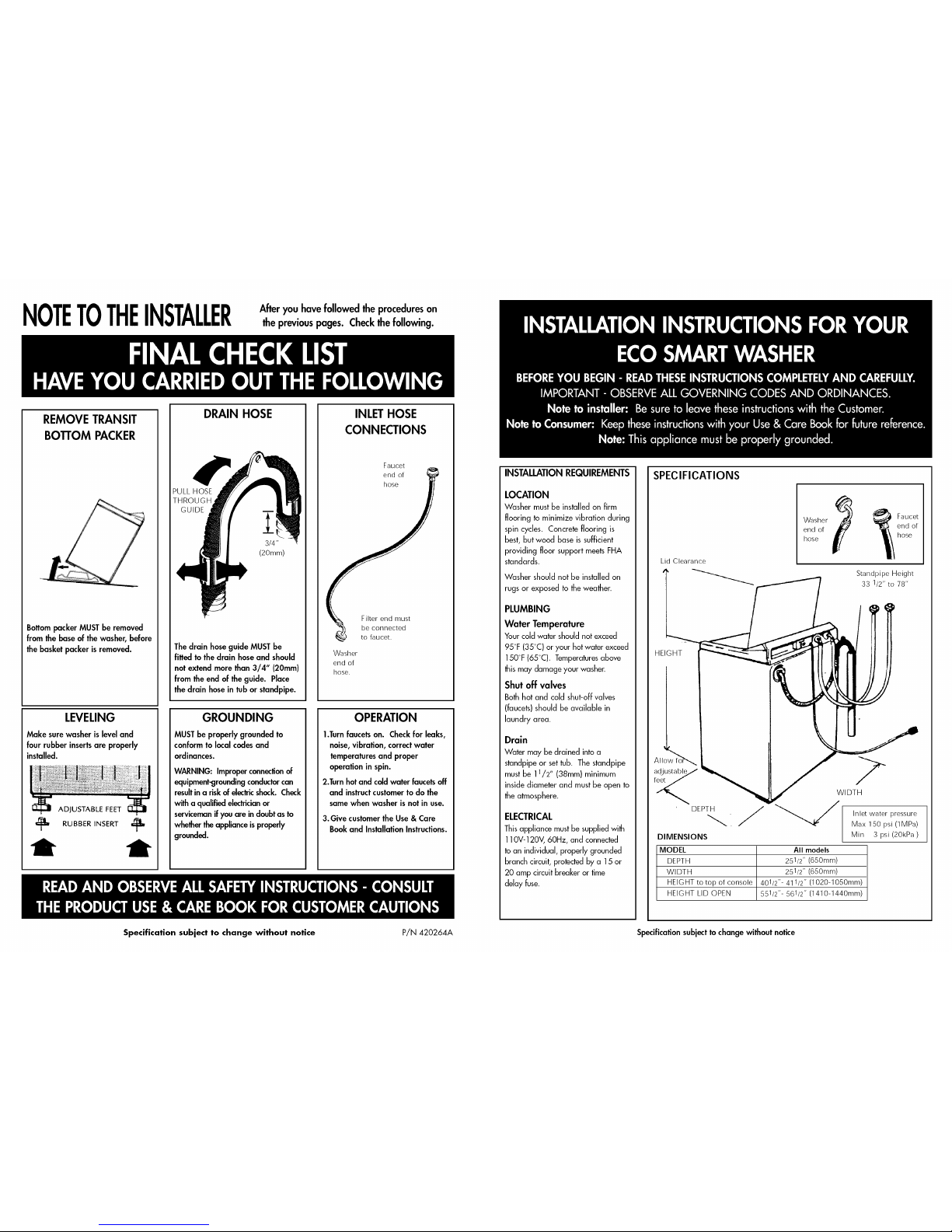
REMOVE TRANSIT
BO'I'rOM PACKER
Bottompacker MUST be removed
from the base of the washer, before
the basket packer is removed.
LEVELING
Make sure washer is level and
four rubber insertsare properly
installed.
ADJUSTABLE FEET
_m RUBBER INSERT _'_
DRAIN HOSE
PULL HOSE
THROUGH
GUIDE m
3/4"
(20mm)
The drain hoseguide MUST be
fitted to the drain hose and should
not extend more than 3/4" (20mm)
from the end of the guide. Place
the drain hose in tub or standpipe.
GROUNDING
MUST be properly grounded to
conform to local codes and
ordinances.
WARNING: Improperconnection of
equipment-groundingconductor can
resultina riskof electricshock. Check
with a qualified electricianor
servicemanif you are in doubt as to
whethertheappliance is properly
grounded.
INLETHOSE
CONNECTIONS
Faucet
end of
hose
Filter end must
be connected
to faucet.
Washer
end of
hose.
OPERATION
1.Turnfaucets on. Check for leaks,
noise, vibration, correct water
temperatures and proper
operation in spin.
2.Turn hot and cold water faucetsoff
and instructcustomer to do the
same when washer is not in use.
3. Give customer the Use & Care
Book and Installation Instructions.
INSTALLATION REQUIREMENTS
LOCATION
Washer must be installed on firm
flooring to minimize vibration during
spin cycles. Concrete flooring is
best, but wood base is sufficient
providing floor support meets FHA
standards.
Washer should not be installed on
rugs or exposed to the weather.
PLUMBING
Water Temperature
Your cold water should not exceed
95°F (35°C) or your hot water exceed
150°F (65°C). Temperaturesabove
this may damage your washer.
Shut off valves
Both hot and cold shut-off valves
(faucets) should be available in
laundry area.
Drain
Water may be drained into a
standpipe or set tub. The standpipe
must be 11/2" (38mm) minimum
inside diameter and must be open to
the atmosphere.
ELECTRICAL
This appliance must be supplied with
110V-120V, 60Hz, and connected
to an individual, properly grounded
branch circuit, protected by a 15 or
20 amp circuit breaker or time
delay fuse.
SPECIFICATIONS
Lid Clearance
Washer
end of
hose
_ Faucet
end of
hose
Standpipe Height
33 1/2" to 78"
HEIGHT
! I
Allowfo_
adjustablee//
DEPTH
DIMENSIONS
WIDTH
/
Inlet water pressure /
Max 150 psi (1MPa)
J
Min 3 psi (20kPa)
MODEL All models
DEPTH 251/2" (650mm)
WIDTH 251/2" (650mm)
HEIGHT to top of console 401/2"- 411/2" (1020-1050mm)
HEIGHT LID OPEN 551/2 "- 561/2" (1410-1440mm)
Specification subject to change without notice P/N 420264A Specificationsubject to change without notice
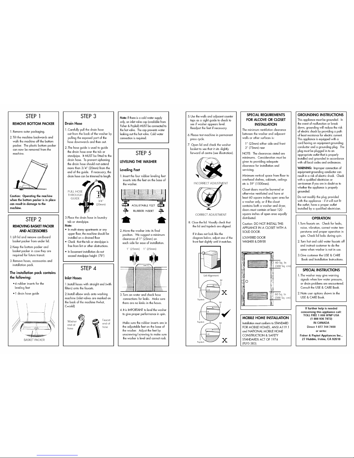
STEP1
REMOVE BOTTOM PACKER
1.Remove outer packaging.
2.Tilt the machine backwards and
walk the machine off the bottom
packer. The plastic bottom packer
can now be removed from the
machine.
Caution: Operating the machine
when the bottom packer is in place
can result in damage to the
machine.
STEP2
REMOVING BASKETPACKER
AND ACCESSORIES
1.Lift lid and remove cardboard
basket packer from under lid.
2.Keep the bottom packer and
basket packer in case they are
required for future transit.
3. Remove hoses, accessories and
installation pack.
The installation pack contains
the following:
*4 rubberinsertsfor the
levelingfeet
• 1 drain hoseguide
\ /
/ ' /
! t J /
BASKETPACKER
STEP3
Drain Hose
1.Carefully pull the drain hose
out from the back of the washer by
pulling the exposed part of the
hose downwards and then out.
2.The hose guide is used to guide
the drain hose over the tub or
standpipe. It MUST be fitted to the
drain hose. To prevent siphoning
the drain hose should not extend
more than 3/4" (20mm) from the
end of the guide. If necessary, the
drain hosecan be trimmed to length
PULL HOSE
THROUGH
GUIDE
3/4"
(20ram)
3.Place the drain hose in laundry
tub or standpipe.
Note:
• In multi-storeyapartments or any
upper floor, the machine should be
installed on a drained floor
• Check that the tub or standpipe is
free from lint or other obstructions.
• In basementinstallationdo not
exceed standpipe height. (78")
STEP4
Inlet Hoses
1.Install hoses with straight end (with
filters) onto the faucets.
2.Install elbow ends onto washing
machine (inlet valves are marked on
the back of the machine H=hot,
C=cold)
Washer
end or
hose
Faucet
end of
hose
Note: If there is a cold water supply
only, an inlet valve cap (available from
Fisher& Paykel)MUST be connected to
the hot valve. Thecap preventswater
leaking out the hot valve. Cold water
connection is required.
STEP5
LEVELING THE WASHER
Leveling Feet
1. Insert the four rubber leveling feet
inserts into the feet on the base of
the washer.
ADJUSTABLE FEET
RUBBER INSERT
2.Move the washer into its final
position. We suggest a minimum
clearance of 1" (25mm) on
each side for ease of installation.
1" (25mm) 1" (25ram)
3.Turn on water and check hose
connections for leaks. Make sure
there are no kinks in the hoses.
4. It is IMPORTANTto level the washer
to give proper performance in spin.
Make sure the rubber inserts are in
the adjustable feet on the base of
the washer. Adjust the feet by
unscrewing/screwing to make sure
the washer is level and cannot rock.
5. Use the walls and adjacent counter
tops as a sight guide to check to
see if washer appears level.
Readjust the feet if necessary.
6. Pleasetest machine in permanent
press cycle.
7. Open lid and check the washer
basket to see that it sits slightly
forward of centre (see illustration).
INCORRECTADJUSTMENT
CORRECT ADJUSTMENT
8. Close the lid. Visually check that
the lid and topdeck are aligned.
If it does not look like the
diagram below, adjust one of the
front feet slightly until it matches.
Lid Alignment
lid
SPECIAL REQUIREMENTS
FOR ALCOVE OR CLOSET
INSTALLATION
The minimum ventilation clearance
between the washer and adjacent
walls or other surfaces is:
I" (25mm) either side and front
3" (75mm) rear
NOTE: The clearances stated are
minimums. Consideration must be
given to providing adequate
clearance for installation and
servicing.
Minimum vertical space from floor to
overhead shelves,cabinets, ceilings
etc is 59" (1500mm).
Closet doors must be Iouvered or
otherwise ventilated and have at
least 60 square inches open area for
a washer only, or if the closet
contains both a washer and dryer,
doors must contain at least 120
square inches of open area equally
distributed.
Caution: DO NOT INSTALLTHIS
APPLIANCE IN A CLOSETWITH A
SOLID DOOR.
LOUVEREDDOOR
WASHER & DRYER
i !-
/,
'10
!r
! !
60 Sq. In
(388 Sq. cm,
60 Sq. In
(388 Sq. cm)
MOBILE HOME INSTALLATION
Installationmustconform to STANDARD
FOR MOBILE HOMES, ANSI A119.1
and NATIONAL MOBILE HOME
CONSTRUCTION & SAFETY
STANDARDS ACT OF 1974
(PL93-383).
GROUNDING INSTRUCTIONS
This appliance must be grounded. In
the event of malfunction or break
down, grounding will reduce the risk
of electric shock by providing a path
of least resistancefor electric current.
This appliance is equipped with a
cord having an equipment-grounding
conductor and a grounding plug. The
plug mustbe plugged in to an
appropriate outletthat is properly
installed and grounded in accordance
with all local codes and ordinances.
WARNING: Improper connection of
equipment-grounding conductor can
resultin a risk of electricshock. Check
with a qualified electrician or
serviceman if you are in doubt as to
whether the appliance is properly
grounded.
Do not modify the plug provided
with the appliance - if it will not fit
the outlet, have a proper outlet
installed by a qualified electrician.
OPERATION
1.Turn faucets on. Check for leaks,
noise, vibration, correct water tem-
peratures and proper operation in
spin. Check lid locks during spin.
2.Turn hot and cold water faucets off
and instruct customer to do the
same when washer is not in use.
3.Give customer the USE & CARE
Book and Installation Instructions.
SPECIAL INSTRUCTIONS
1.The washer may give warning
signals when low water pressure,
or drain problems are encountered.
Consult the USE & CARE Book.
2. Note user options shown in the
USE& CARE Book.
If further help is needed
concerning this appliance call:
TOLL FREE 1 888 9FNP USA
(1 888 936 7872)
IN CANADA
Direct 1 877 744 7400
or write:
Fisher & Paykel Appliances Inc.,
27 Hubble, Irvine, CA 92618
 Loading...