

Fisher & Paykel GWL08US Service Manual
SMART DRIVE
ELECTRONIC WASHING MACHINE
MODEL GWL08US
Service Supplement to be used in conjunction with GWL03US
Service Manual Part Number PM912
Fisher & Paykel Appliances Inc
27 Hubble, Irvine, California, CA92618, USA,
Ph: 949 790 8900, Fax: 949 790 8911
200434

C O N T E N T S
1.0 INTRODUCTION ........................................................................................................................3
PERFORMANCE CHANGES ........................................................................................................3
MACHINE SIZE SETTING CHANGES ........................................................................................ 3
ELECTRONIC MODULES ............................................................................................................3
2.0 MACHINE SIZE SETTING MODE ............................................................................................ 4
3.0 DIAGNOSTIC MODE .................................................................................................................5
3.1 EXAMPLES OF BINARY CODE ...........................................................................................5
3.2 LID SWITCH & OUT OF BALANCE SWITCH TEST .........................................................6
3.3 DRAIN PUMP TEST................................................................................................................6
3.4 WATER VALVE TEST ...........................................................................................................6
3.5 RE-START FEATURE.............................................................................................................7
3.6 RE-CYCLE FEATURE ............................................................................................................ 7
3.7 HOT TUB FLAG...................................................................................................................... 7
3.8 FAULT DISPLAY....................................................................................................................8
4.0 WIRING DIAGRAM.................................................................................................................... 8
5.0 DETAILED FAULT CODES.......................................................................................................9
FAULT DESCRIPTIONS..............................................................................................................10

3
1.0 INTRODUCTION
MODEL GWL08US
This Service Supplement contains information on the Product Specifications, Diagnostic Mode and
the Detailed Fault Codes. For all other Service and Option Adjustment information please refer to
your GWL03 Service Manual part number 426348.
Note: The water temperature adjustment in the Option Adjustment mode is only available on
model GWL03. Model GWL08 has 5 preset temperatures which are factory set and are non
adjustable.
The detailed fault codes in this service supplement can also be used for Model GWL03 Smart
Drive Washing Machines.
PERFORMANCE CHANGES
The introduction of model GWL08 sees changes to the way the Smart Drive senses and reacts to
what is going on in the basket.
The Smart Drive Washing machines has two load sensing methods to ensure the right wash
action is used for the type and size of the wash load.
• LSD - Load Sensing Detection is used to continually sense the load and automatically adjust
the agitation profiles to suit the wash load. It is also used to determine when a maximum
capacity profile needs to be used. If the machine is operating on the high water level, regular
cycle, with a very large heavy load, then the load sensing detection will activate the Maximum
Capacity Profile.
• MCP - Maximum Capacity Profile is in the high water level regular cycle only. It is clearly
noticeable as the machine will stop agitating and restart with a perceivably different profile. It
usually occurs 3-6 minutes into the wash and will, of course, only occur if the machine is
extremely heavily loaded.
MACHINE SIZE SETTING CHANGES
With model GWL08 we have made changes to the way the size setting is set into the Motor
Controller Module's memory. There is no longer a size switch in the Display Module and the Size
Setting has to be manually entered. See Machine Size Setting Mode on page 5. Failure to do this
will result in the machine faulting to detailed fault code 9.
ELECTRONIC MODULES
Electronic Modules are not inter-changeable between models.
The different modules for the different models can be identified by their colour. GWL03 modules
are green and the latest GWL08 modules are yellow.
It is important not to mix the different colored modules as there is different sensing between the
models and you will find that the washing machine will not work. It will automatically display a
fault code and beep if the modules have been mismatched.
4
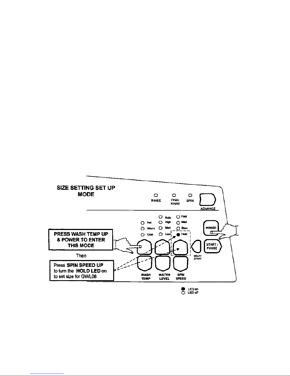
2.0 MACHINE SIZE SETTING MODE
It is important to set the size setting into the Motor Controller's memory whenever a replacement
Motor Controller or Display Module is fitted to the washing machine. Failure to do this will result
in the machine faulting to detailed fault code 9.
The size setting procedure for GWL08 differs from the previous GWL03 Smart Drive washing
machine.
To enter the Machine Size Setting Mode:
1. Turn the power on at the power point and off at the console.
2. Press and hold the WASH TEMP UP button then press the POWER button. The machine will
give 4 short beeps and the pattern of the LED's will change.
3. Press the SPIN SPEED UP until the SPIN HOLD LED turns on.
4. Press the POWER button to exit this mode and return to normal operation.
5
3.0 DIAGNOSTIC MODE
The DIAGNOSTIC MODE for mode GWL08 now incorporates both the switch test mode and the
data display mode. You no longer have to use the advance button to toggle between them.
To enter the DIAGNOSTIC MODE:
1. Turn the power on at the power point and off at the console.
2. Press and hold the WASH TEMPERATURE DOWN then press the POWER button. The
machine will give 2 short beeps
3. The different levels of information can now be extracted by using the SPIN SPEED UP or the
SPIN SPEED DOWN buttons.
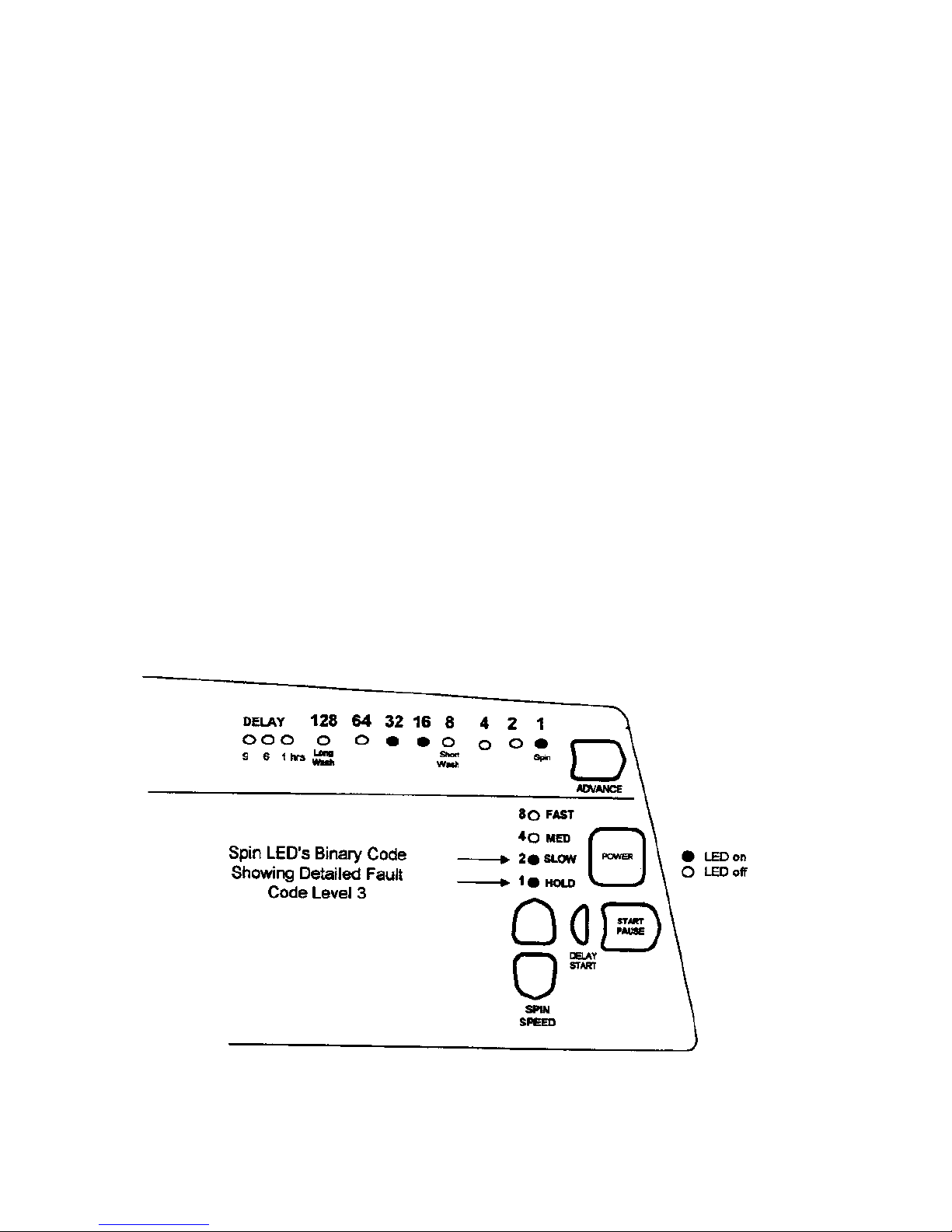
DATA DISPLAY
Press the SPIN SPEED UP button until the HOLD and SLOW SPIN LED's are on, (Binary count 3).
The WASH PROGRESS LED's will now display the fault code.
By using a BINARY NUMBERING SYSTEM each unique fault code can be given a number.
3.1 EXAMPLES OF BINARY CODE
Wash Progress LED’s Binary Code
Detailed Fault Code 32+16+1=49
Note: The detailed fault code will only be displayed for 1 cycle after the fault has been rectified.
6
DIAGNOSTIC MODE cont:
The following tests can be carried out in the diagnostic mode.
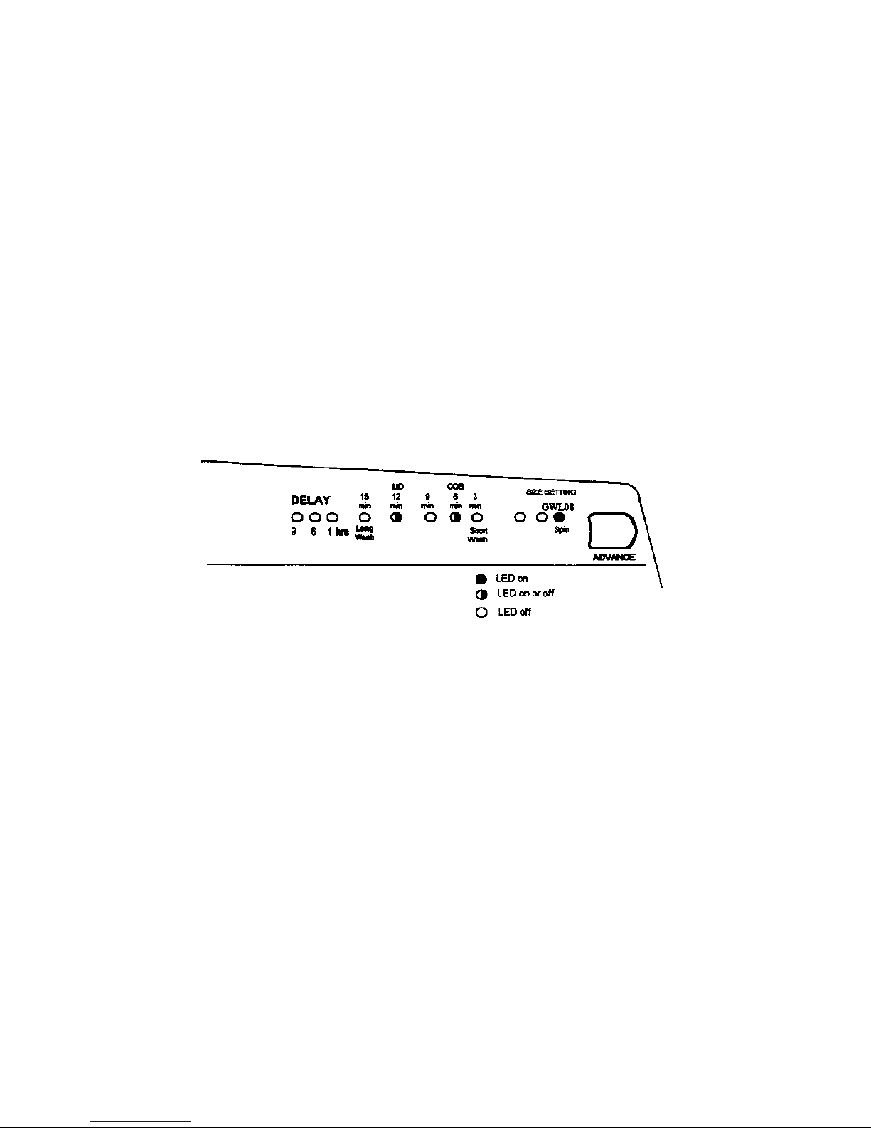
3.2 LID SWITCH & OUT OF BALANCE SWITCH TEST
Press the SPIN SPEED UP button until the MEDIUM SPIN LED is on, (binary count 4).
When the Lid is open the 12 minute wash LED will be on.
Activating the Out of Balance lever under the top deck will cause the 6 minute LED to turn on. The
Out of Balance lever can be activated by moving the inner basket towards the right hand corner of
the cabinet. It will take up to 1 second for the LED to respond after the Out of Balance has been
activated.
Also when in this mode with the MEDIUM SPIN SPEED LED on, the SPIN LED will display the
SIZE SETTING.
SPIN LED on = MODEL GWL08
3.3 DRAIN PUMP TEST
The REGULAR CYCLE button turns the drain pump on or off. The REGULAR LED will turn
on when the pump is on. This feature can be used to drain the tub.
3.4 WATER VALVE TEST
Press the WASH TEMPERATURE DOWN button to turn the Cold Water Valve on. The Cold
Water LED will also turn on.
Press the WASH TEMPERATURE UP button to turn the Hot Valve on. The Hot Water LED will
also turn on.
NOTE:
The drain pump test, water valve test, restart and recycle features can be used on any level in the
diagnostic mode.
 Loading...