

Fisher & Paykel GWL03US Service Manual
SMART DRIVE
ELECTRO NIC WASHI NG MA CHINE
MODEL GWL03US
120 Volt 60 Hz
Fisher & Paykel Appliances Inc
27 Hubble, Irvine, California, CA92618, USA,
Ph: 949 790 8900, Fax: 949 790 8911
426348


3
C O N T E N T S
SMART DRIVE ELECTRONIC WASHING MACHINE..................................................................1
1.0 SPECIFICATIONS....................................................................................................................6
FINISH.........................................................................................................................................6
DIMENSIONS..............................................................................................................................6
2.0 UNPACKING............................................................................................................................8
3.0 INSTALLATION......................................................................................................................8
HOT WATER TEMPERATURE.................................................................................................9
DRAINING..................................................................................................................................9
4.0 INTRODUCTION...................................................................................................................10
5.1 ELECTRONICS SYSTEMS...................................................................................................10
5.1.1 MOTOR............................................................................................................................11
5.1.2 ROTOR POSITION SENSOR MODULE.......................................................................11
5.1.3 MOTOR CONTROLLER MODULE ..............................................................................12
5.1.4 DISPLAY MODULE .......................................................................................................12
5.1.5 PRESSURE SENSOR......................................................................................................12
5.1.6 INLET CHAMBER..........................................................................................................12
5.1.7 WATER VALVES...........................................................................................................13
5.2 MECHANICAL SY STE M ......................................................................................................14
5.2.1 DIRECT DRIVE...............................................................................................................14
5.2.2 FLOATING BASKET......................................................................................................14
5.2.3 AUTOMATIC WATER LEVEL SYSTEM.....................................................................15
5.2.4 DRAIN PUMP..................................................................................................................15
5.2.5 LID SWITCH...................................................................................................................16
5.2.6 LINT REMOVAL SYSTEM............................................................................................16
6.0 OPTION ADJUSTMENT MODE...........................................................................................17
6.1 WASH WATER TEMPERATURE........................................................................................18
METHOD OF SETTINGS THE WASH TEMPERATURE .....................................................18
WATER TEMPERATURE SETTINGS....................................................................................18
EXAMPLE OF ADJUSTING WASH TEMPERATURE.........................................................19
6.2 RINSE OPTIONS....................................................................................................................21
METHOD OF SELECTING RINSE OPTIONS........................................................................21
6.3 END OF CYCLE WARNING BEEPS...................................................................................22
METHOD OF ADJUSTING THE NUMBER OF END OF CYCLE WARNING BEEPS......22
6.4 VOLUME OF WATER USED IN THE WATER SAVER OPTION ....................................23
6.5 OUT OF BALANCE RECOVERY........................................................................................23
TO PROGRAM THE AUTOMATIC OUT OF BALANCE RECOVERY...............................23
6.6 AUTO WATER LEVEL ADJUSTMENT..............................................................................24
7.0 OPERATION / USE & CARE................................................................................................25
7.1 WASH CYCLES.....................................................................................................................25
7.1.1 WASH CYCLE TIMES...................................................................................................25
7.1.2 AGITATOR PROFILE COMPARISONS.......................................................................26
7.1.3 CUSTOMIZING THE WASH CYCLES.........................................................................26
7.2 FAVORITE CYCLE...............................................................................................................26
PROGRAMMING THE FAVORITE CYCLE..........................................................................26
7.3 WATER SAVER OPTION.....................................................................................................27
AMOUNT OF WATER USE D IN THE WATER SAVER RINSE..........................................27
7.4 MANUAL WATER LEVEL SELECTION ............................................................................27
7.5 AUTOMATIC WATER LEVEL............................................................................................27
7.6 DELAY START......................................................................................................................28

4
TO USE DELAY STAR T..........................................................................................................28
7.7 FABRIC SOFTENER DISPENSER.......................................................................................29
7.8 USER FAULTS.......................................................................................................................30
8.0 DEMONSTRATION MODE..................................................................................................31
TO SELECT DEMONSTRATION MODE...............................................................................31
9.0 DIAGNOSTIC MODE............................................................................................................32
TO SELECT DIAGNOSTIC MODE.........................................................................................32
9.1 LED TEST...............................................................................................................................32
9.2 SWITCH TEST.......................................................................................................................32
9.2.1 LID SWITCH...................................................................................................................32
9.2.2 OUT OF BALANCE SWITCH........................................................................................32
9.2.3 LOCATION SWITCH.....................................................................................................33
9.3 DRAIN PUMP TEST..............................................................................................................33
9.4 WATER VALVE TEST..........................................................................................................33
9.5 RE-START FEATURE...........................................................................................................33
9.6 RE-CYCLE FEATURE...........................................................................................................34
9.7 DATA DISPLAYS..................................................................................................................34
TO SELECT DATA DISPLAYS...............................................................................................34
10.0 FAULT MODE......................................................................................................................35
10.1 BINARY CODE....................................................................................................................35
EXAMPLES USING THE DA TA DISPLAYS.........................................................................35
10.2 FAULT CODE DESCRIPTIONS.........................................................................................36
1. (00000 001) MOTOR CONTROL MODULE FAULT........................................................36
2. (00000 010) MOTOR CONTROL MODULE FAULT........................................................36
3. (00000 011) MOTOR CONTROL MODULE FAULT........................................................36
6. (00000 110) MOTOR CONTROL MODULE FAULT........................................................36
7. (00000 111) DISPLAY MODULE FAULT..........................................................................36
9. (00001 001) LOCATION SWITCH ERROR.......................................................................36
10. (00001 010) TEMPERATURE SENSOR ERROR.............................................................37
11. (00001 011) PRESSURE SENSOR FAULT.......................................................................37
12. (00001 100) FLOOD PROTECTION ERROR ...................................................................37
36. (00100 100) WATER LEAK FAULT.................................................................................37
37. (00100 101) PUMP BLOCKED ERROR...........................................................................37
38. (00100 110) PRESSURE SENSOR FAULT.......................................................................38
39. (00100 111) PRESSURE TUBE FAULT...........................................................................38
40. (0 0101 000) BASKE T DIS-EN GAGE FAULT.................................................................38
41. (00101 001) TEMPERATURE SENSOR FAULT.............................................................39
43. (00101011) OUT OF BALANCE SWITCH FAULT.........................................................39
44. (00101 100) WATER IN TUB DURING SPIN..................................................................39
47. (00101 111) BASKET DIS-ENGAGE FAULT..................................................................39
48. (00110 000) HOT AND COLD VALVE FAULTY ...........................................................40
49. (00110 001) COLD VALVE FAULTY ..............................................................................40
50. (00110 010) HOT VALVE FAULTY.................................................................................40
81 - 95. (0101X XXX)...............................................................................................................40
104. (01101000) ........................................................................................................................40
106. (01101 010) DISPLAY TO MOTOR CONTROL MODULE COMMUNICATIONS
ERRORS.....................................................................................................................................40
105. (01101 001) DISPLAY TO MOTOR CONTROL MODULE COMMUNICATIONS
TIME-OUT ERROR...................................................................................................................40
107. (01101 011) MOTOR CONTROL MODULE RESET ERROR.......................................41
130. (10000 010) SINGLE ROTOR POSITION SENSOR ERROR........................................41
131. (10000 011) REPETITIVE ROTOR POSITION SENSOR ERROR...............................41

5
132. (10000 100) SINGLE CURRENT TRIP...........................................................................41
133. (10000 101) REPETITIVE CURRENT TRIP ..................................................................41
136. (10001 000) MOTOR STALL...........................................................................................42
160. (10100 000) BASKET ENGAGED...................................................................................42
10.3 MOTOR CONTROLLER VOLTAGE CHECK...................................................................43
10.4 DIAGNOSTIC FLOW CHART............................................................................................44
11.0 REMOVING AND REFITTING OF ELESTRONIC MODULES......................................45
11.1 ESD PRECAUTIONS...........................................................................................................45
11.2 CONNECTORS.....................................................................................................................46
11.2.1 EASY OFF CONNECTORS..........................................................................................46
11.2.2 EDGE CONNECTOR....................................................................................................46
11.2.3 OTHER CONNECTORS...............................................................................................46
11.3 ACCESS TO CONSOLE AREA..........................................................................................47
11.4 DISPLAY MODULE ............................................................................................................47
11.5 MOTOR CONTROLLER MODULE ...................................................................................48
11.6 INLET CHAMBER & WATER VALVES...........................................................................49
11.7 ROTOR POSITION SENSOR..............................................................................................49
11.8 DIAGNOSTIC TEST............................................................................................................50
11.9 LID SWITCH........................................................................................................................50
12.0 MECHANICAL DISASSEMBLY & REASSEMBLY ........................................................51
12.1 BEARING REPLACEMENT KIT........................................................................................51
12.2 MECHANICAL DISASSEMBLY PROCEDURE...............................................................52
12.3 MECHANICAL REASSEMBLY PROCEDURE................................................................63
13.0 SELECTED ARES OF SER VICE ........................................................................................71
13.1 PUMP BLOCKAGE..............................................................................................................71
13.2 COMPLETE PUMP FAILURE – BURNT OUT..................................................................72
13.3 MOTOR.................................................................................................................................73
6
1.0 SPECIFICATIONS
FINISH
Cabinet Prepaint (Polyester)
Lid Polypropylene
Console Polypropylene
Basket stainless steel (grade 430T)
Tub Polypropylene
Agitator Polypropylene
Cover Polypropylene
Touch Panel Polypropylene
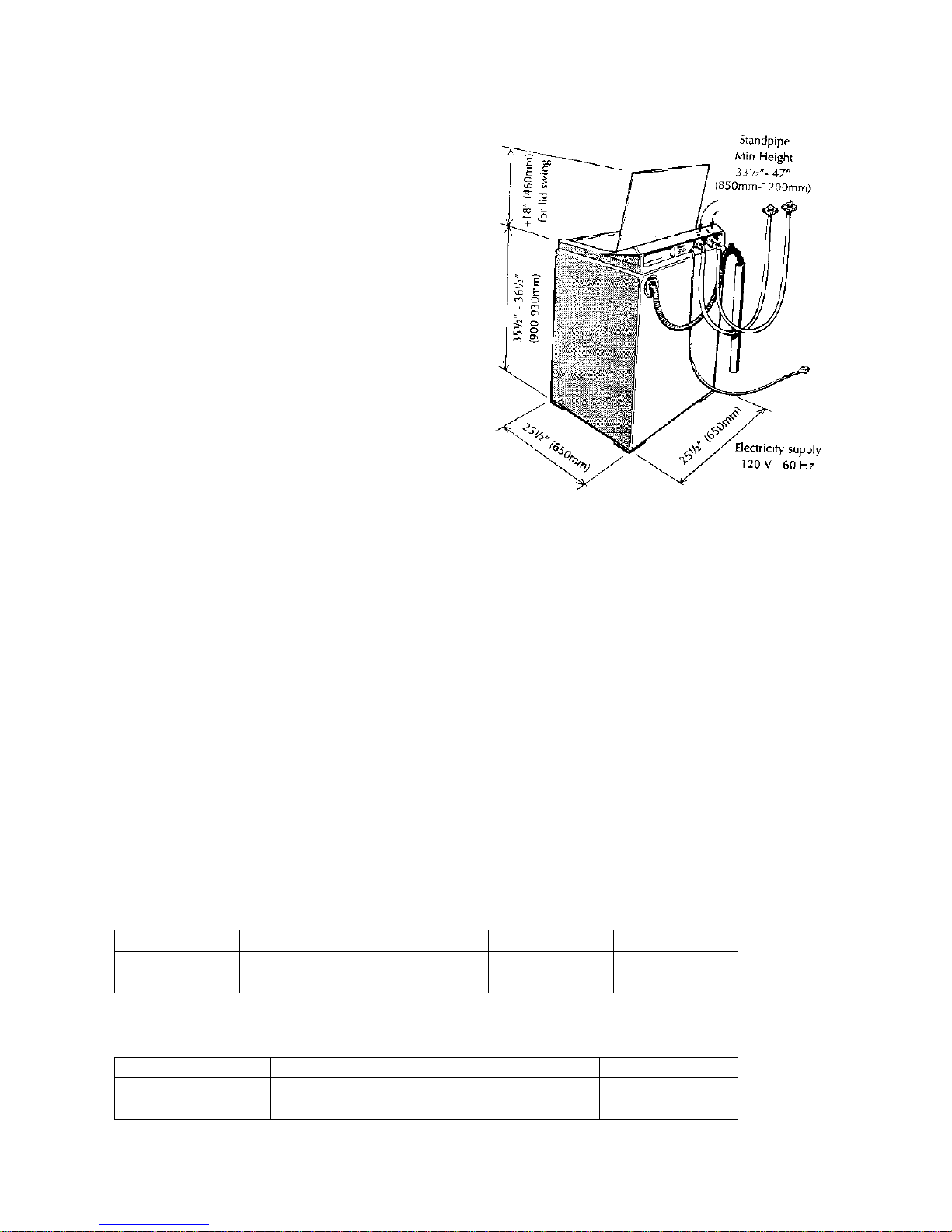
DIMENSIONS
Height Floor to Lid
Lid closed 35 ½“ – 36½ “ (900mm – 930mm)
Lid open Add 18” (460mm)
Height Floor to Console
39 ½ “- 40 ½” (1000mm – 1030mm)
Width 25 ½” (650mm)
Depth 25 ½” (650mm)
Inlet Hose
Length 43” (1090mm)
Weight
Packed 126 lbs (57.3 kg)
Unpacked 112 lbs (55.3 kg)
Capacity (Full Load)
Dry weight 15.4 lbs (7 kg)
Water consumption per fill
(approx. figure for high water level)
High Medium high Medium Medium low Low
24 US gals 20 US gals 16 US gals 13 US gals 8 /us gals
90 litres 75 litres 60 litres 45 litres 32 litres
Water consumption per cycle
(approx. figures for high water level)
Shower Rinse Spray & Deep Rinse 1 Deep Rinse 2 Deep Rinses
40 US gals 54 US gals 46 Us gals 63 US gals
150 litres 205 litres 175 litres 225 litres

7
Water fill temp (Factory Settings)
Hot 120oF (49oC)
Hot/Warm 105oF (40oC)
Warm 95oF (35oC)
Warm/Cold 85oF (29oC)
Cold as per cold water supply temperature.
Recommended inlet hot water temperature not to exceed 150oF (65oC)
Wash Motor
Electronically commutated direct drive
DC Motor
Motor Resistance per winding
6.1 ohms @ 68oF (20oC)
Pump Motor
120V AC, 60Hz
Thermal cut out fitted
Flow Rate 5.8 gal/min. (22 l/min.)
Pump motor resistance 6.5 ohms + 5%
Water Valves
12 Volts DC Resistance 15 ohms
Cold Valve Proportional 15 ohms
Operating pressure Max 150 psi (1034 kPa)
Min 3 psi (20kPa)
Basket Speed
Fast Spin 1,000 rpm
Medium Spin 700 rpm
Slow 300 rpm
Stir Speed 25 rpm
Fabric Softener Dispenser
Dosage (75cc)
Electric Supply
120V AC 60Hz
Max Current
6 amps
8
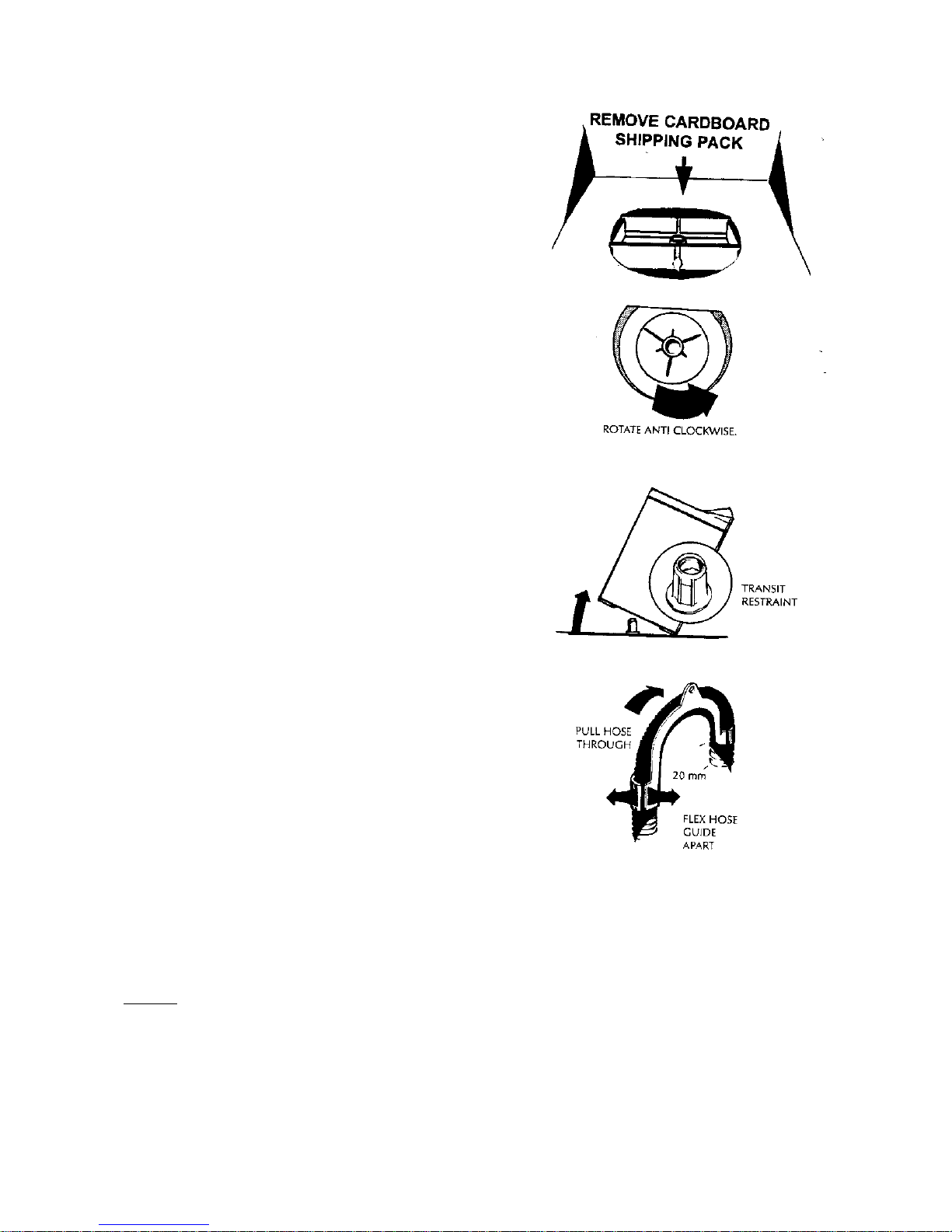
2.0 UNPACKING
1. Remove the outer packing, leave the washer standing
upright on the cardboard bottom.
2. Lift the lid and remove the cardboard shipping pack
from under the lid.
3. Remove the hoses and accessories.
4. Rotate the agitator anti-clockwise for 3 revolutions to
unscrew the red shipping restraint from the base of the
washer. (The wash basket will then be free to move from
side to side).
5. The cardboard bottom packer is now free to be
removed from the washer. Tilt the washer and check that
the red shipping restraint has come away with the
cardboard bottom. Keep the shipping pack and shipping
restraint in case they are required for future transit.
3.0 INSTALLATION
1. Uncoil the cord set.
2. Remove the ribbed drain hose from the fixture on the
left hand side of the rear panel by carefully pulling the
exposed part of the hose downwards and outwards.
3. Connect the drain hose to the laundry tub or
standpipe. The hose guide, included in the accessory kit,
is to guide the hose over the laundry tub or standpipe.
The hose must not extend beyond the hose guide more
than 1” (25mm). If necessary the drain hose can be
trimmed to length.
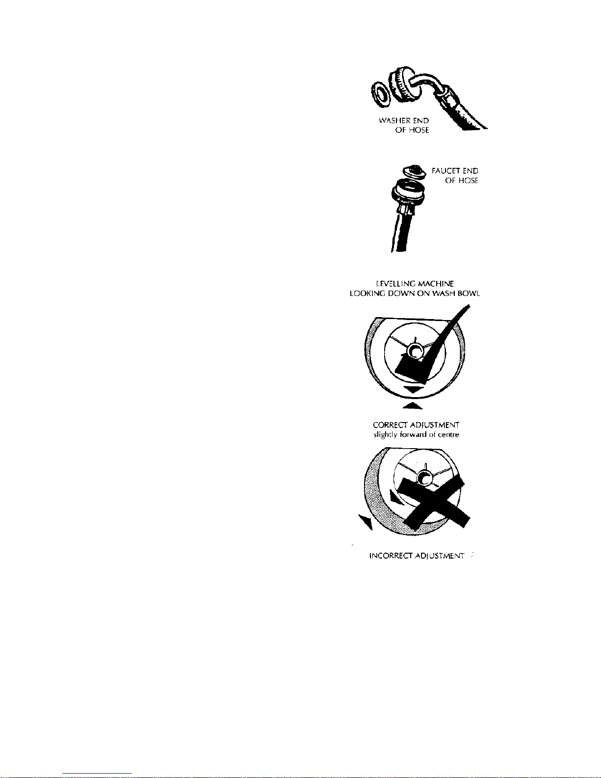
4. Place the sealing washers (from the accessory kit)
into the elbow ends of the plastic inlet hoses and connect
to the washer inlet valves. The inlet valves are marked
on the rear of the washer.
H = hot C = cold
NOTE: The elbow end of the hose has a non standard
thread and must be connected to the washer water
inlet valves only.
9
5. Place the screened sealing washers (from the
accessory kit) into the straight end of the inlet hoses and
connect to the faucets.
Turn on the water and check the hose connections for
leaks.
6. Move the washer into its final position. We suggest a
minimum clearance of ¾ “ (20mm) either side of the
washer for ease of installation. Make sure there are no
kinks in the hoses.
7. It is IMPORTANT to level the washer. The rubber
inserts (from the accessory kit) must be fitted into
adjustable feet on the base of the washer. Adjust the
levelling feet by unscrew/screwing so that the stainless
steel basket sits in the cover opening slightly forward of
the center.
8. Make sure the washer is firm on all levelling feet.
9. Plug the cord set into the wall socket.
HOT WAT ER TEMPERATURE
L The hot water should not exceed 150oF (65oC).
Water at excessively high temperatures will cause
damage to the washer.
L The cold water should not exceed 95oF (35oC).
DRAINING
L Draining must comply with the local codes.
L In multi-storey apartments or an upper floor, the
washer should be installed on a drained floor.
10
4.0 INTRODUCTION
The washer design has a number of unique features not found on any other washer. These will be
explained in the following sections.
5.1 ELECTRO NICS SYSTEMS
The washer electronics consists of 4 main parts:
a) Motor
b) Rotor Position Sensor
c) Motor Controller Module
d) Display Module
e) Pressure Sensor
f) Inlet Chamber
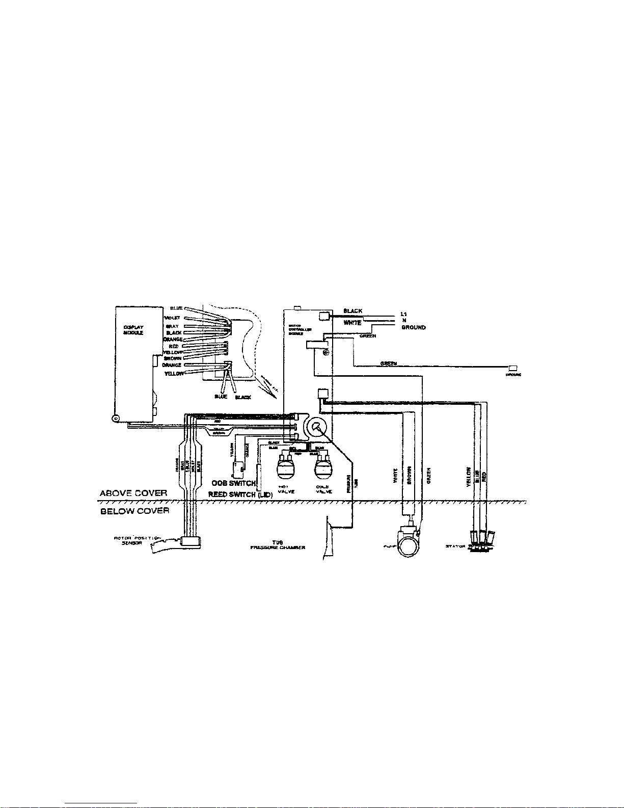
ELECTRONIC BLOCK DIAGRAM
11
5.1.1 MOTOR
The motor is a 3 phase, 42 pole, DC brushless motor. Rotation of the motor is controlled by a
microprocessor located in the Motor Controller Module.
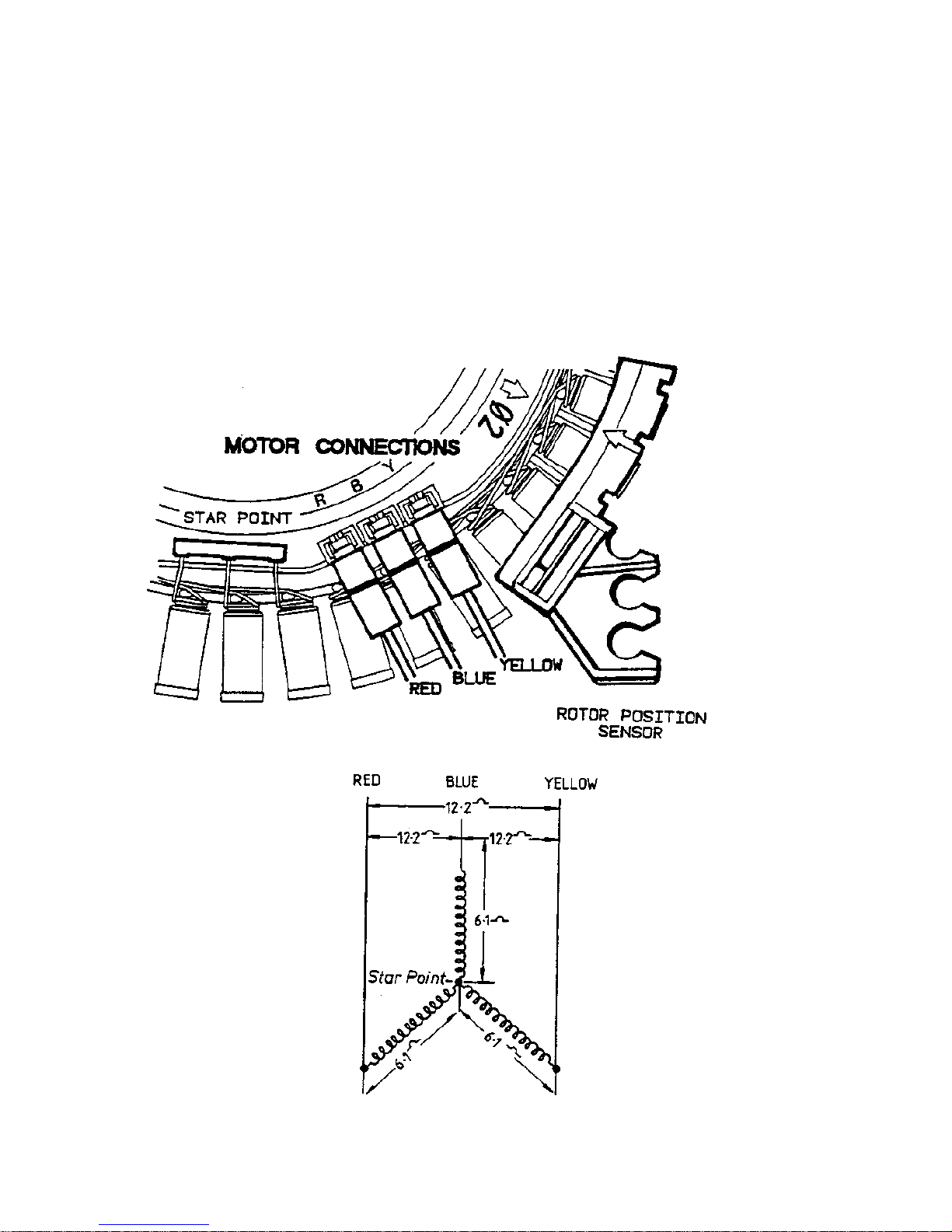
The Motor consists of a STATOR (stationary part) and ROTOR (rotating part).
5.1.2 ROTOR POSITI ON SENSOR MODULE
Fitted to the Stator is the Rotor Position Sensor Module. This detects the position of the rotor and
feeds a signal back to the Motor Controller Module.
To check the Rotor Position Sensor use a RPS tester part number 502105.
12
5.1.3 MOTOR CONTROLLER MODULE
The Motor Controller Module contains the circuits needed to control the water valves, pump and
the main motor. It contains a microprocessor that controls these functions as well as accepting
signals from the Rotor Position Sensor and Display Module. The Motor Controller Module and
Display Module are continuously communicating with each other, passing information back and
forth on the required wash actions and diagnostic data.
5.1.4 DISPLAY MODULE
The Display Module contains a second microprocessor. The Display Module takes the inputs from
the front panel (i.e. user settings) and sends a command to the Motor Controller Module. It also
controls the output to the LED’s and beeper.
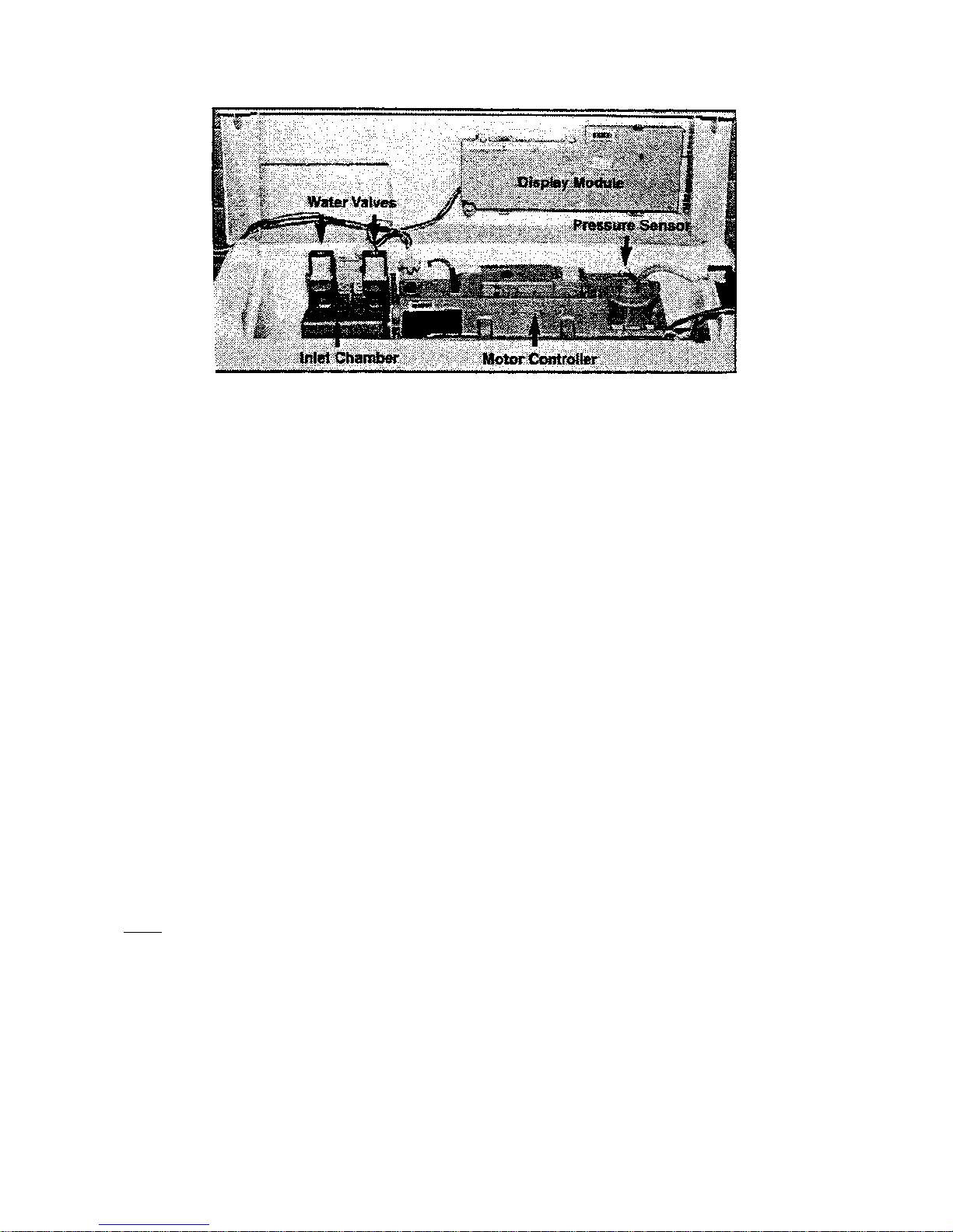
5.1.5 PRESSURE SENSOR
The Pressure sensor is located inside the Motor Controller Module. Unlike normal pressure
switches it does not contain contacts, but an electronic circuit that continuously measures the water
level. The pressure sensor cannot be removed from the Motor Controller for servicing.
5.1.6 INLET CHAMBER
The inlet chamber serves two purposes;
a) As a reservoir for the cooling water. The electronics in the Motor Controller Module are cooled
by water. The inlet Chamber is connected to an aluminium heatsink, which is part of the Motor
Controller Module. During the fill cycles, water flows through one side of the inlet chamber,
through one side of the heatsink back on the other side through the second chamber of the inlet
chamber and then into the tub.
Note: Should the electronics become too hot, the cold valve will be turned on to fill the heatsink
with cold water. Therefore, a small quantity of water may be discharged into the basket during the
cycle. This is normal and not a fault.
b) To mix the incoming hot and cold water. This is part of the automatic wash water temperature
system. For this to work effectively the incoming water has to be mixed before entering the
Motor Controller Module. The water temperature is measured by a device located within the
Motor Controller Module. The water valves are then controlled to maintain the correct water
temperature into the tub.
13
5.1.7 WATER VALVES
The washer is fitted with an automatic water temperature fill system. The electronics control the
water valves so that a constant water temperature is achieved in the tub irrespective of the
temperatures and pressures of the household hot and cold water systems. This system will also
compensate for changes in pressure and temperature during the washer’s fill cycle.
To achieve this the cold valve is a special type of valve called a proportional water valve. Unlike
conventional water valves which are either fully on or fully off, the proportional water valve can be
controlled so that it can turn on at any water flow rate between fully on and fully off. The hot water
is controlled by using a conventional type of water valve.
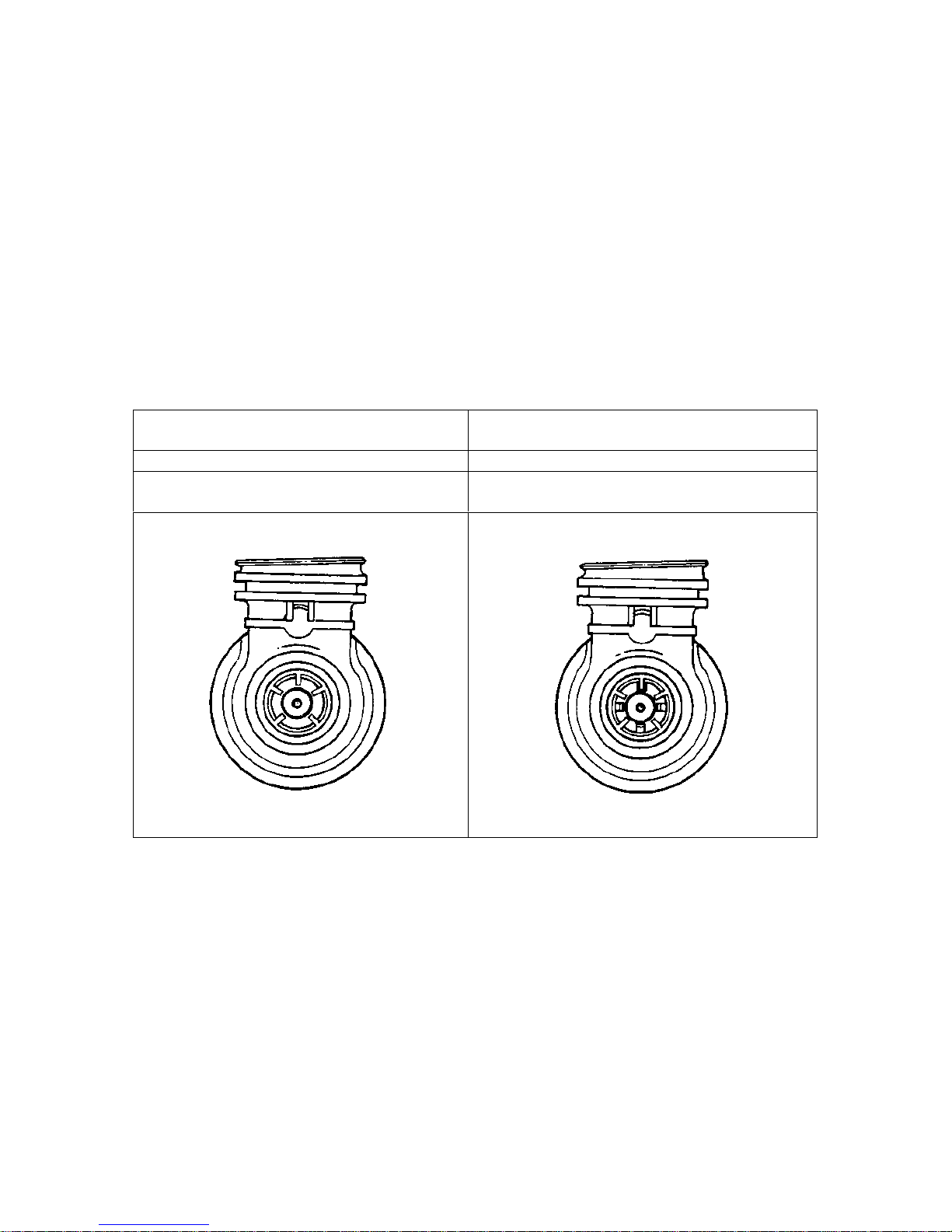
It is important that the correct water valve is fitted should they ever need replacement. The valves
can be identified by the following features:
Proportional Valve Standard Valve
Filter colour – White Filter colour – Red
Shape of water valve plunger.
Has no stand offs Has four stand offs visible from outlet nozzle
Difference between Proportional and Standard Valve
14
5.2 MECHANICAL SYSTEM
5.2.1 DIRECT DRIVE
In this washer the motor shaft is connected directly to the agitator. The DIRECT DRIVE motor has
eliminated the need for pulleys, belts, gearboxes and other electro-mechanical items used in other
designs. The single shaft design also reduces the number of seals.
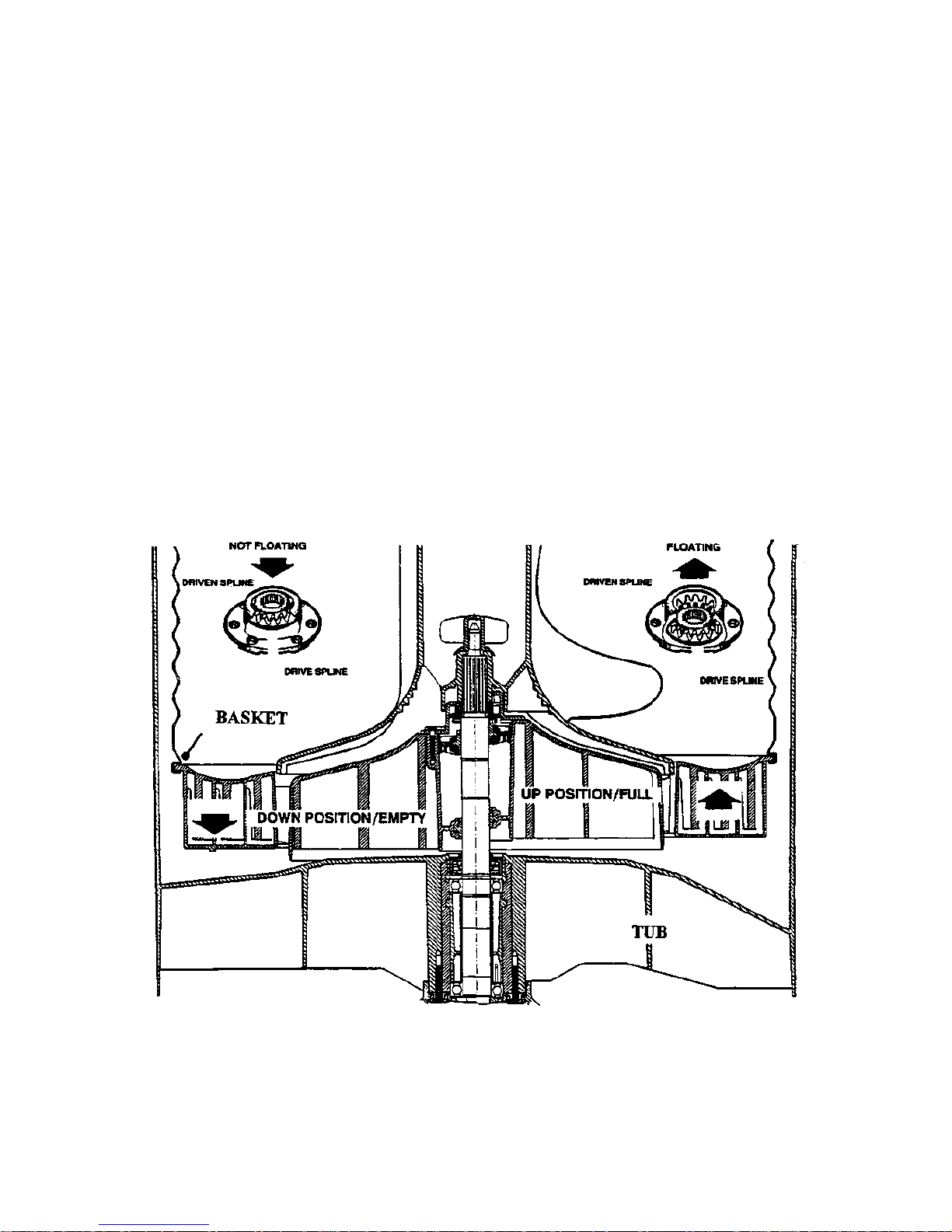
5.2.2 FLOATING BASKET
During spin, the agitator and basket have to be coupled together and turn as a single unit, whilst in
agitate the agitator and basket have to be free to rotate independently.
The washer basket is free to move in a vertical direction. At the base of the basket is a flotation
chamber. As the water level increases the basket floats and disengages the driven spline from the
drive spline. This agitator is now decoupled from the basket and can move freely in both directions.
When the water is draining from the washer the basket settles back down onto the drive spline and
re-engages the driven spline. The agitator and basket are now coupled together and turn as one unit.
FLOATING BASKET
15
Detection of Basket Float Off Point
During fill the basket rotates to ensure that the clothes are evenly saturated with water. Whilst the
tub is filling, the agitator will occasional stop and commence a number of special agitate actions.
During these actions the washer determines if the basket has floated. If it has, the microprocessor
can now determine the correct water level and will continue filling to that level. If the basket has
not floated off, the washer will continue filling and check again later.
Note: The water level at which the basket floats off is not necessarily the same as the final water
level.
Detection of Basket Re-Engagement
After the washer has pumped out the water, the basket will sink down and re-engage onto the drive
spline. To ensure the basket has re-engaged correctly, the washer will carry out a basket re-engage
test. This test consists of a series of short agitate strokes before the spin cycle starts. A sound may
be heard as the basket re-engages.
5.2.3 AUTOMATIC WATER LEVEL SYSTEM
The floating basket is also used to detect correct water level for the clothes load in the washer.
The point at which the basket starts to float is determined by the load size. The greater the load, the
more water is needed before the basket will float. By detecting the point at which the basket floats,
the microprocessor can determine the correct water level.
If the operator has manually chosen a level that is too low for the load, the washer will override that
choice and fill to the correct level. If the operator has chosen a level that is higher than necessary,
the washer will still fill to the operator’s chosen level.
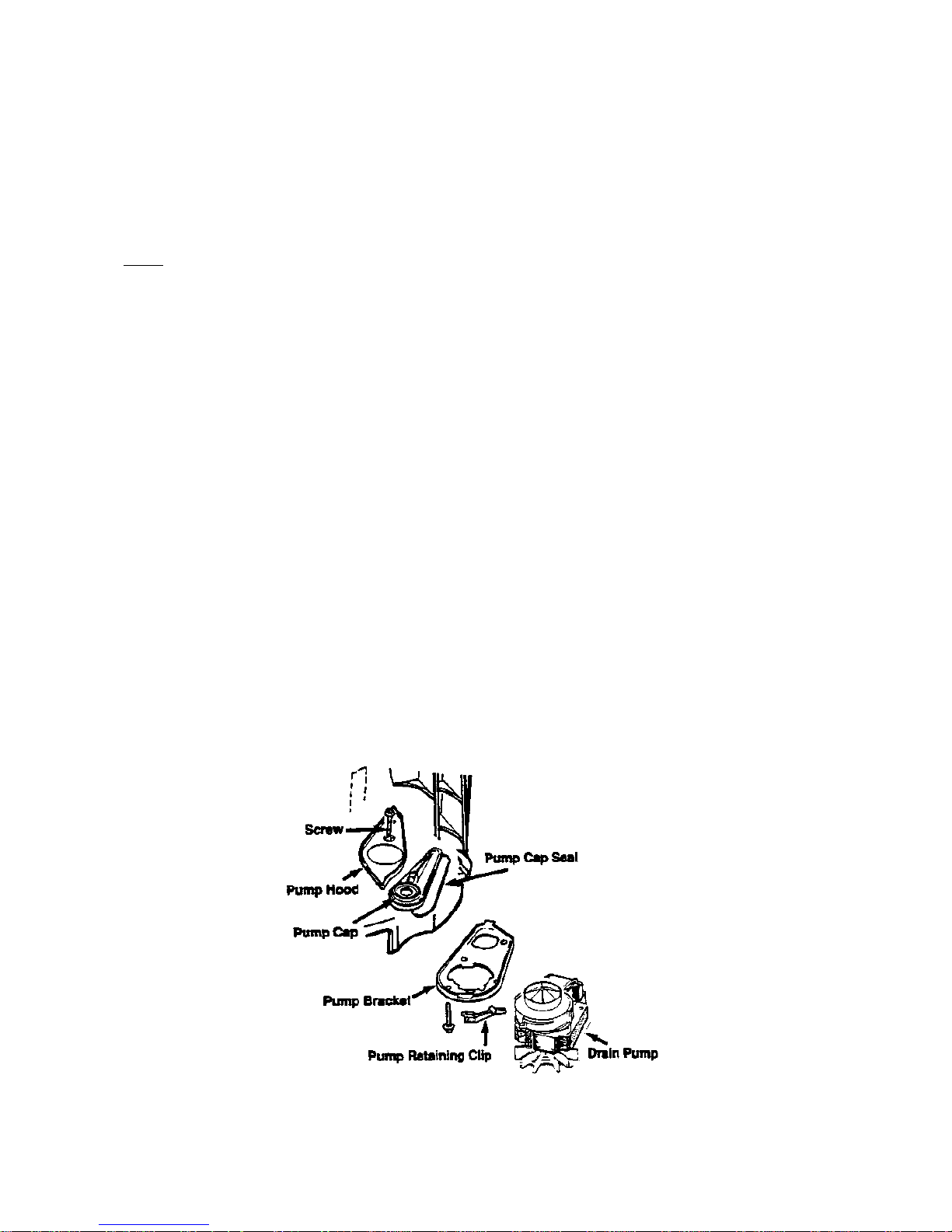
5.2.4 DRAIN PUMP
The drain pump motor is attached directly to the base of the tub. The pump housing is an integral
part of the tub. This eliminates tub to pump hoses and the accompanying seals, clips etc. The
pump is accessible by removing the inspection hatch on the front of the washer. It is also accessible
for cleaning from the top by removing the agitator and basket.

16
5.2.5 LID SWITCH
Lid opening and closing is detected by a reed switch located under the right hand side of the cover,
approx. 5” (125mm) from the front. The reed switch is activated by a magnet which is moulded
into the lid. A protrusion can be seen on the underside of the lid where the magnet is located. If the
lid is raised the washer will stop and go into PAUSE. To start the washer again close the lid, and
push the START/PAUSE button.
The washer should turn of when the lid is opened no more than 2” (50mm) and restart at least ½ “
(12mm) before the lid is closed.
5.2.6 LINT REMOVAL SYSTEM
As a result of the agitator action, lint and wash water are sucked into the agitator stem and down to
the base of the agitator, where they are directed into the cavity between the basket and tub. The
extruded holes in the basket are shaped to allow the wash water to flow back into the tub, but
prevent the lint from following.
The lint then floats to the surface of the water, between the basket and tub and remains there until it
is flushed out the drain at the end of the wash cycle.
17
6.0 OPTION ADJUSTMENT MODE
The owner can customise the washer to there own preference. This is done in the OPTION
ADJUSTMENT MODE.
The features that can be adjusted are:
a) Wash Water Temperature
b) Rinse Options
c) End of Cycle Warning Beeps
d) Volume of water used in the Water Saver Option
e) Auto Water Level Adjustment
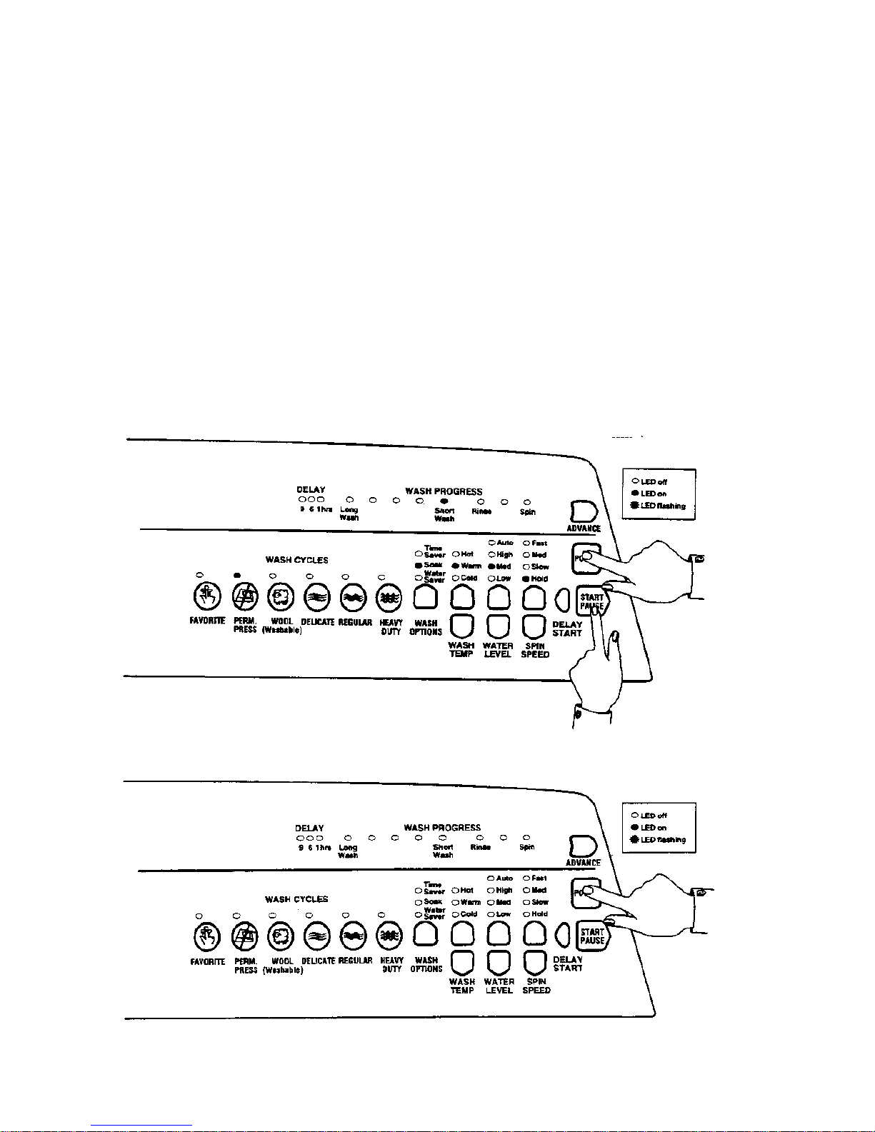
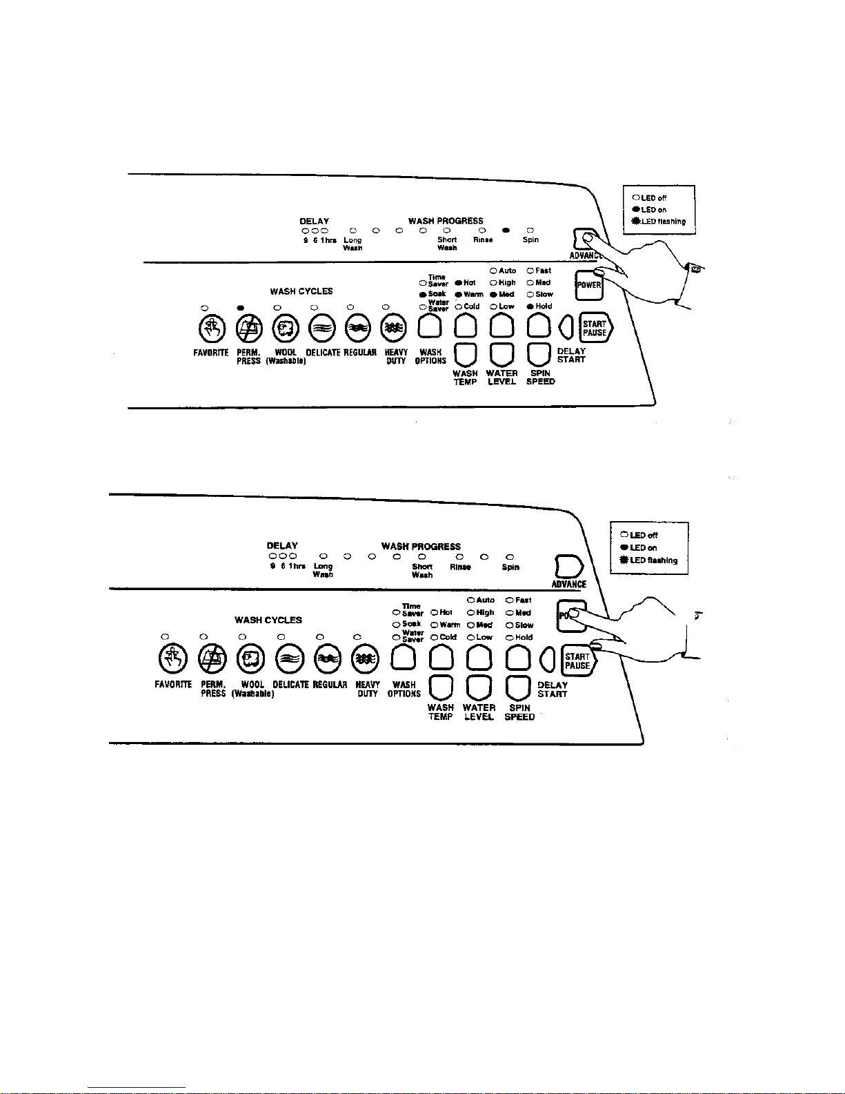
To Select the OPTION ADJUSTMENT MODE
1. Press and hold down the START/PAUSE button, then press the POWER button.
Two quick beeps will sound and the LED’s on the front panel will change.
The controls and LED’s on the front panel will now serve different functions from normal.
2. The washer can now be programmed to suit the owner’s preference.
3. To return the washer to normal operation, press the POWER button.

18
6.1 WASH WATER TEMPER ATURE
The water temperature of each of the wash temperature settings can be changed.
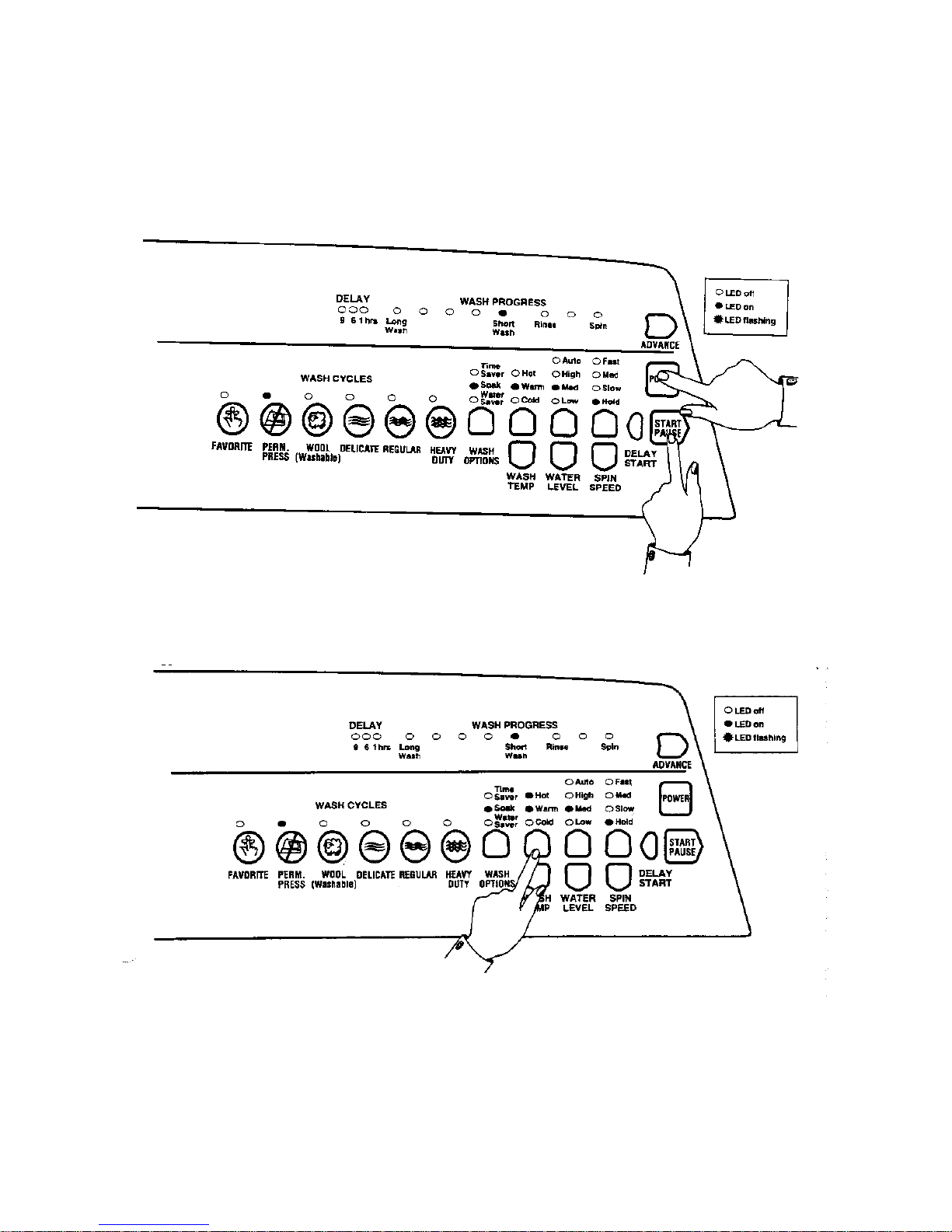
METHOD OF SETTINGS T HE WASH TEMPERATURE
1. Select the OPTION ADJUSTMENT MODE by pressing and holding down the
START/PAUSE button, then pressing the POWER button.
2. Use WASH TEMP ERA TURE buttons and LED’s to select the temperature setting to be
adjusted, ie. Cold, Cold/Warm, Warm, Warm/Hot, or Hot.
3. Use the ADVANCE button and WASH PROGRESS LED’s to increase or decrease the
temper ature. Each tim e the ADVANCE button is pressed, the WASH PROGRESS LED’s
will advance one position to the right. This increases the temperature by approximately 2oF
(1oC). (See Table 2 for the approximate temperatures for each of the settings).
4. Select the next temperature range to be changed with the WASH TEMP ERA TURE buttons
and repeat Step 3. Each Temperature range can be adjusted using this method.
5. To return the washer to Normal operation, press the POWER button.
NOTES
1. Do not use the household water faucets or water heater controls to vary the wash temperature.
The automatic water temperature control system will compensate for variations in household
water temperature and pressure. Adjusting the water pressure or the water heater temperature,
WILL NOT alter the wash temperature.
2. If the washer is used in an installation where only a cold water supply is available, then the cold
temperature range must be selected and the “cold water only” setting must be chosen in the
Option Adjustment mode. Refer Table 2. A blanking cap must be fitted to the hot inlet valve.
If the temperature is set at any other level, the washer will expect hot water when filling. As it
will not detect any hot water, it will eventually display the USER FAULT (see USER FAULT)
that there is no hot water.
3. We recommend that the hot water temperature setting on the household water heater does not
exceed 150oF (65oC) for personal safety and washer reliability.
4. If the temperature of the cold water supply is warmer than the selected temperature, a cold water
user warning will sound because the washer will be unable to control the water temperature to
the required temperature. To correct this re-adjust the cold temperature to cold only setting or a
temperature that is above the cold water supply.
WATER TEMPERATURE SETTINGS
Temperature
Range
15 min
Wash
LED on
12 min
Wash
LED on
9 min
Wash
LED on
6 min
Wash
LED on
3 min
Wash
LED on
Rinse
LED
on
Final
Rinse
LED on
Spin
LED on
Hot 112 114 116 118 120 122 124 126
Warm/Hot 97 99 101 103 105 107 109 111
Warm 87899193959799101
Cold/Warm7779818385878991
Cold *F 54 56 58 60 62 64 66
Table 2. Water Temperature Settings (oF) *F = Cold water only
19
EXAMPLE OF ADJUSTING WASH TEMPERATURE
Adjust Warm/Hot temperature to 109oF (43oC).
1. To select the OPTION ADJUSTMENT MODE by pressing and holding down the
START/PAUSE button, then press the POWER button.
2. To select the WARM/HOT temperature. Press the WASH TEMPERATURE UP button
once.
20
3. Press the ADVANCE button twice. The final Rinse LED will be on. This is the 109oF LED as
shown on Table 2.
4. Press the POWER button to return to normal operation.
21
6.2 RINSE OPTIONS
The washer may be used in a large number of different installations. To cater for these variations
the Rinse type can be changed.
First Rinse Description Comments
RINSE
OPTION (1)
Spray Rinse Clothes have water sprayed
over them as they are spinning.
Factory Setting. Gives the
best performance for suds
removal and water usage
In areas where the water supply contains solid contaminates, ie bores, the spray rinse action
can result in these contaminates being deposited on the fabrics. In this case it would be
better to use Option (2) or (3).
RINSE
OPTION (2)
Spin only Clothes are spun only to
remove excess water & suds.
Does not give as good a
suds removal as Option
(1) but uses lass water
than Option (3)
RINSE
OPTION (3)
Deep Rinse Tub is fill with water and then
agitated.
Gives better suds removal
but increases water usage.
The second rinse is always a deep rinse. This is followed by a spin cycle.
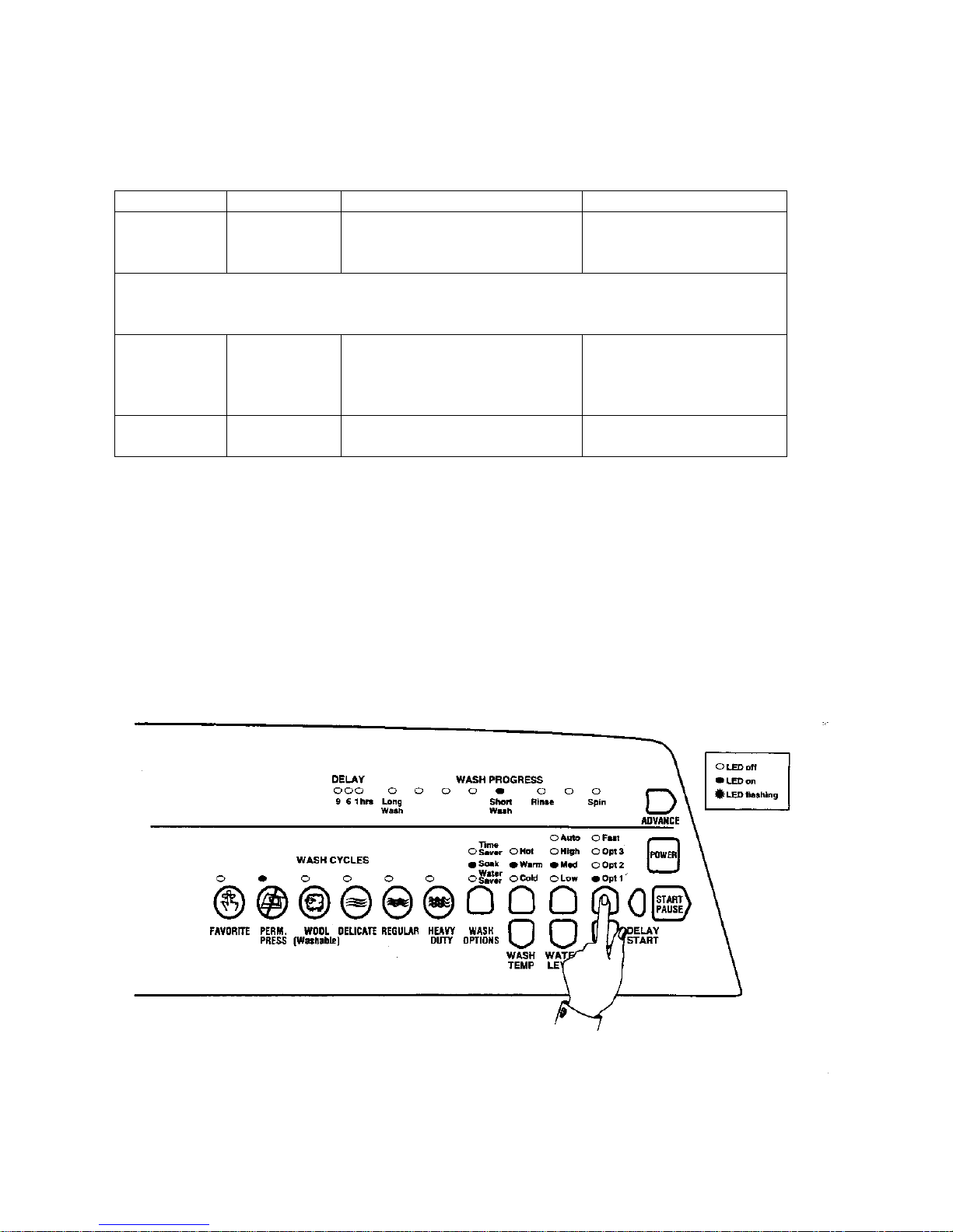
M ETHOD OF SELECTING RINSE OPTIONS
1. Select the OPTION ADJUSTMENT MODE by pressing and holding down the
START/PAUSE button, then pressing the POWER button.
2. Press the SPIN SPEED buttons to select Rinse options.
Hold LED ON OPTION (1) – Factory Setting
Slow LED ON OPTION (2)
Medium LED ON OPTION (3)
To return the washer to Normal operation, press the POWER button.

22
6.3 END OF CYCLE WARNING BEEPS
The washer finishes each cycle by sounding a series of warning beeps. In some circumstances the
user may wish to increase the number of beeps or eliminate them altogether.
MET HOD OF ADJUS TING T HE NUMBER OF END OF CYCLE WARNING
BEEPS
1. Select the OPTION ADJUSTMENT MODE by pressing and holding down the
START/PAUSE button, then pressing the POWER button.
2. Use the WASH OPTIONS button and LED’s to select the required option. Pressing the
WASH OPTIONS button will cause the LED’s to change.
Time saver LED ON 15 beeps
Soak LED ON 5 beeps – Factory Setting
Water Saver LED ON 0 beeps
3. To return the washer to Normal operation, press the POWER button.

23
6.4 VOLUME OF WATER USED IN THE WATER SAVER
OPTION
You can increase or decrease the volume of water used during the Water Saver option.
1. Select the OPTION ADJUSTMENT MODE by pressing and holding down the
START/PAUSE button, then pressing the POWER button.
2. Use the WATER LEVEL buttons to select the water volume.
HIGH LED ON more water
MED. LED ON normal – Factory Setting
LOW LED ON less water
3. Press POWER button to return to normal operation.
6.5 OUT OF BALANCE RECOV ERY
If the washer senses an unbalanced load it will stop and give a short burst of beeps every five
seconds and the RINSE or SPIN LED will flash. As well as the current SPIN SPEED LED. The
load must be redistributed and the washer restarted manually.
The washer can also be programmed to automatically correct an out of balance load. If it detects an
unbalanced load, it will fill with water and agitate for a number of minutes. This will redistribute
the load before the washer tries to spin up again. If this action does not clear the out of balance load
after a few attempts the washer will stop.
TO PROGRAM THE AUTOMATIC OUT OF BALANCE RECOVE RY
1. Select the OPTION ADJUSTMENT MODE by pressing and holding down the
START/PAUSE button, then pressing the POWER button.
2. Use the HEAVY DUTY button to select the Out of Balance recovery option.
HEAVY DUTY LED ON automatic
HEAVY DUTY LED OFF stops and sounds warning
3. Press POWER button to return to normal operation.
 Loading...