

Fisher & Paykel ELBA OR60, ELBA OR90 Series, ELBA OR60 Series Installation Instructions And User Manual
NZ AU
Installation instructions
and User guide
Freestanding cooker
OR60 & OR90 models


1
Safety and warnings
2
Installation instructions -
OR60 models 6
Installation instructions -
OR90 models 16
Using your oven
26
Cooking functions
28
Using your gas cooktop
29
Cooktop troubleshooting
33
Care and cleaning
34
Warranty and service
49
Important!
SAVE THESE INSTRUCTIONS
The models shown in this User Guide may not be available in all markets and are
subject to change at any time. For current details about model and specification
availability in your country, please go to our website www.elba.co.nz or contact your
local Fisher & Paykel dealer.
Contents
2
Safety and warnings
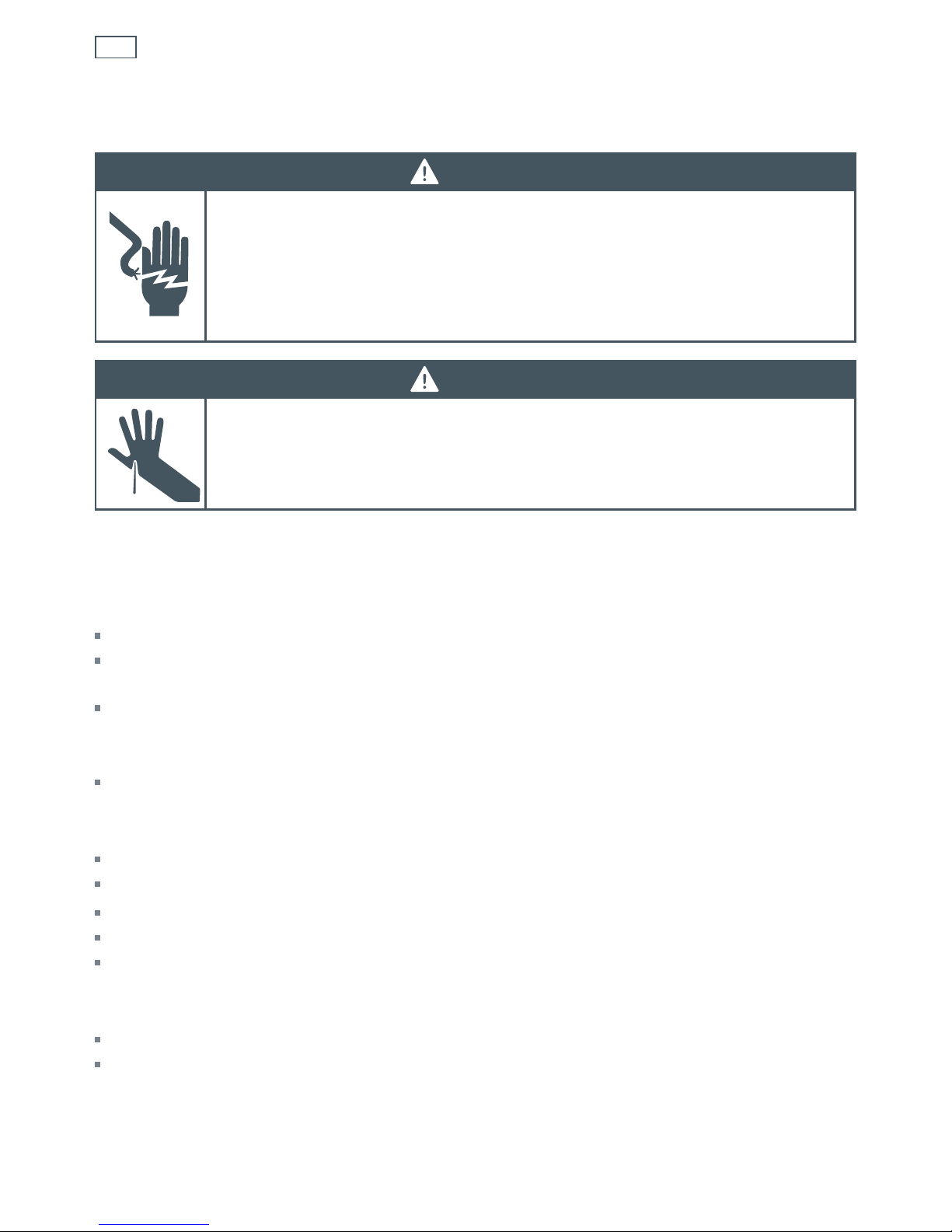
WARNING!
Electrical Shock Hazard
Always disconnect the cooker from the mains electricity supply before
carrying out any maintenance operations or repairs.
Failure to follow this advice may result in death or electrical shock.
Important safety instructions
General
To avoid hazard, follow these instructions carefully before installing or using this product.
Please make this information available to the person installing the product as it could reduce
your installation costs.
These products are registered:
in New Zealand at www.energysafety.govt.nz
in Australia with AGA at www.aga.asn.au.
This appliance must be installed in accordance with these installation instructions, local
gas fitting regulations, municipal building codes, water supply regulations, electrical wiring
regulations, AS/NZS 5601.1 - Gas Installations and any other relevant statutory regulations.
Failure to install the cooker correctly could invalidate any warranty or liability claims.
Some appliances have a protective film. Remove this film before using the cooker.
Do not modify this appliance.
This appliance is to be installed and serviced only by an authorised person.
Do not operate your appliance by means of an external timer or separate remote-control system.
Electrical
This cooker is to be installed and connected to the electricity supply only by an authorised person.
If the installation requires alterations to the domestic electrical system, call a qualified
electrician. The electrician should also check that the electrical system is suitable for the
electricity drawn by the cooker.
Installation
WARNING!
Cut Hazard
Take care - panel edges are sharp.
Failure to use caution could result in injury or cuts.

3
The appliance must be connected to the mains electricity supply, checking that the voltage
corresponds to the value given in the rating plate and that the electrical cable sections can
withstand the load specified on the plate.
A suitable disconnection switch must be incorporated in the permanent wiring, mounted and
positioned to comply with the local wiring rules and regulations. The switch must be of an
approved type installed in the fixed wiring and provide a 3 mm air gap contact separation in all
poles in accordance with the local wiring rules.
In Australia and New Zealand, a switch of the approved type with a 3 mm air gap must be
installed in the active (phase) conductor of the fixed wiring.
The switch must always be accessible.
The power supply cable must not touch any hot parts and must be positioned so that it does not
exceed 75
O
C at any point.
To connect the cooker to the mains electricity supply, do not use adapters, reducers or branching
devices as they can cause overheating and burning.
This cooker must be connected to a suitable double pole control unit adjacent to the cooker. No
diversity can be applied to this control unit.
If the electrical supply cord is damaged, it must only be replaced by an authorised person.
This cooker must be connected to electrical supply using V105 insulated cable (3 x 1.5 mm
2
section).
The cooker must be earthed.
Power supply
OR60 models: 220-240V 50Hz 2480W
OR90 models: 220-240V 50Hz 3050W
Safety and warnings
4
Operation
Your freestanding cooker has been carefully designed to operate safely during normal cooking
procedures. Please keep the following guidelines in mind when you are using it:
Safety and warnings
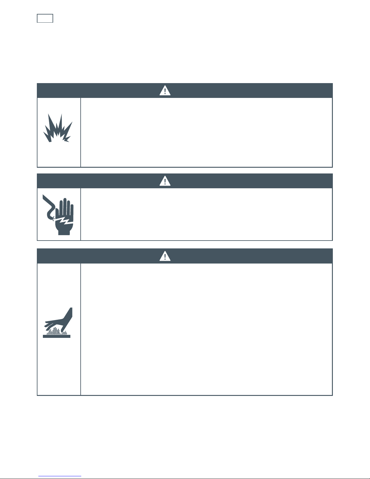
WARNING!
Hot Surface Hazard
Accessible parts may become hot when this cooker is in use.
To avoid burns and scalds keep children away.
Do not touch hot surfaces inside the oven.
Use oven mitts or other protection when handling hot surfaces such as oven
shelves or dishes.
Take care when opening the oven door.
Let hot air or steam escape before removing or replacing food.
Do not touch the cooktop components, burners, trivets/pan supports or the
base when hot.
Before cleaning, turn the cooker off and make sure it is cool.
Failure to follow this advice could result in burns and scalds.
WARNING!
Electrical Shock Hazard
Switch the cooker off at the wall before replacing fuses or the oven lamp.
Failure to do so may result in death or electrical shock.
WARNING!
Explosion Hazard
Do not store flammable materials such as gasoline near the cooktop.
Do not store flammable material in the oven, drawer or storage
compartment.
Do not spray aerosols near the cooktop during use.
Failure to follow this advice may result in death or serious injury.

5
Safety and warnings
Important safety precautions
Never leave the appliance unattended when in use. Boilover causes smoking and greasy
spillovers that may ignite.
Isolating switch: make sure this cooker is connected to a circuit which incorporates an isolating
switch providing full disconnection from the power supply.
Household appliances are not intended to be played with by children.
Children of less than 8 years old must be kept away from the appliance unless continuously
supervised. This appliance can be used by children aged from 8 years and above, and persons
with reduced physical, sensory or mental capabilities or lack of experience and knowledge, if
they have been given supervision or instruction concerning the use of the appliance in a safe way
and they understand the hazards involved. Cleaning and user maintenance shall not be done by
children without supervision.
Safe food handling: leave food in the oven for as short a time as possible before and after
cooking. This is to avoid contamination by organisms which may cause food poisoning. Take
particular care during warmer weather.
Do not place aluminium foil, dishes, trays, water or ice on the oven floor during cooking as this
will irreversibly damage the enamel.
Do not line the walls with aluminium foil.
Do not stand on the door, or place heavy objects on it.
Do not use harsh abrasive cleaners or sharp metal scrapers to clean the oven door glass since
they scratch the surface, which may result in shattering of the glass.
Do not use a steam cleaner to clean any part of the cooker.
Do not use an asbestos mat or decorative covers between the flame and the saucepan as this may
cause serious damage to your cooktop.
Do not place aluminium foil or plastic dishes on the cooktop burners.
Do not let large saucepans or frying pans overlap the bench as this can deflect heat onto your
benchtop and damage the surface.
Do not let large saucepans, frying pans or woks push any other pans aside. This could make them
unstable or deflect heat onto your benchtop and damage the surface.
Saucepan handles may be hot to touch. Ensure saucepan handles do not
overhang other gas burners that are on. Keep handles out of reach of children.
If the electrical supply cord is damaged, it must only be replaced by an authorised person.
This cooker is not to be used as a space heater.
The use of a gas cooking appliance results in the production of heat and moisture in the room in
which it is installed. Ensure the kitchen is well ventilated. Keep natural ventilation holes open or
install a mechanical ventilation device (mechanical extractor hood).
Prolonged intensive use of the appliance may call for additional ventilation, for example opening
of a window, or more effective ventilation, for example increasing the level of mechanical
ventilation where present.
6
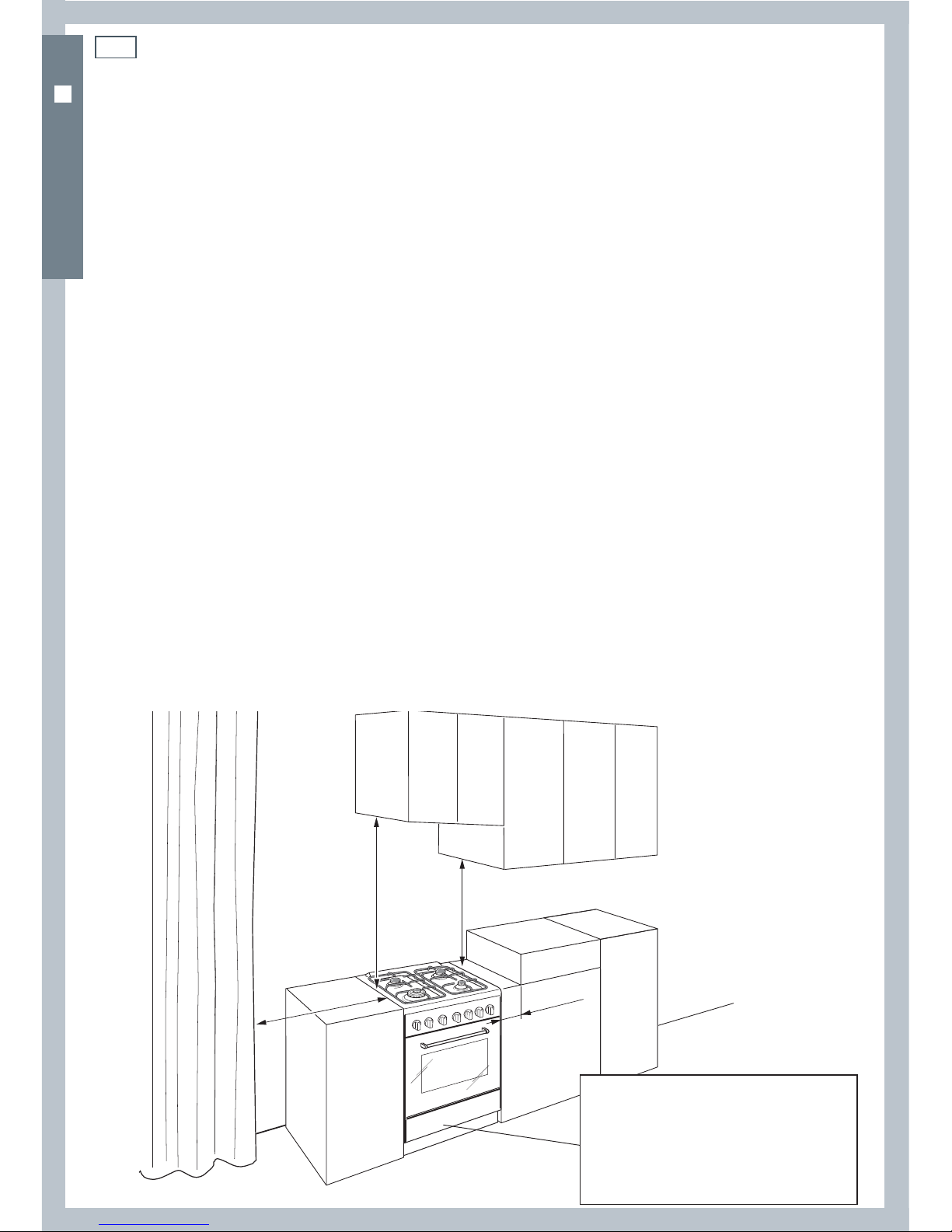
750 mm
500 mm
105 mm
450 mm
Dimensions and clearances
Installation clearances and protection of combustible surfaces shall comply with the current
local regulations eg. AS/NZS 5601.1 Gas Installations code. Installation shall comply with the
dimensions in Fig. 1, bearing in mind the following requirements:
Overhead Clearances
In no case shall the clearance above the highest part of the cooker be less than 600 mm or, for
an overhead exhaust fan, 750 mm. AII other downward-facing combustible surfaces less than
600 mm above the cooker surface shall be protected for the full width of the cooking surface in
accordance with the standards noted above. In no case shall the clearance be less than 450 mm.
Rear and Side Clearances
Where the distance from the periphery of the nearest burner to any vertical combustible surface
is less than 200 mm, the surface shall be protected in accordance with the standards to a height
of not less than 150 mm above the cooking surface for the full width or depth of the cooking
surface.
Where the distance from the periphery of the nearest burner to any horizontal combustible
surface is less than 200 mm, the horizontal surface shall be more than 10 mm below the surface
of the cooking surface, or the horizontal surface shall be above the trivet (see requirements for
vertical combustible surfaces above).
Protection of combustible surfaces
The standards above specify that, where required, protection shall ensure that the surface
temperature of combustible surfaces does not exceed 65°C above room temperature.
Do not install the cooker near flammable materials (eg curtains).
If you stand the cooker on a pedestal, make sure you provide safety measures to keep it in place.
Installation instructionsInstallation instructions
Cooker overall dimensions [mm]
•
height:
min 900 - max 915
•
product width: 598
•
depth: 600
•
cavity width 600
Fig. 1 Dimensions and
distances from cooker
OR60 MODELS
7
Installation instructions
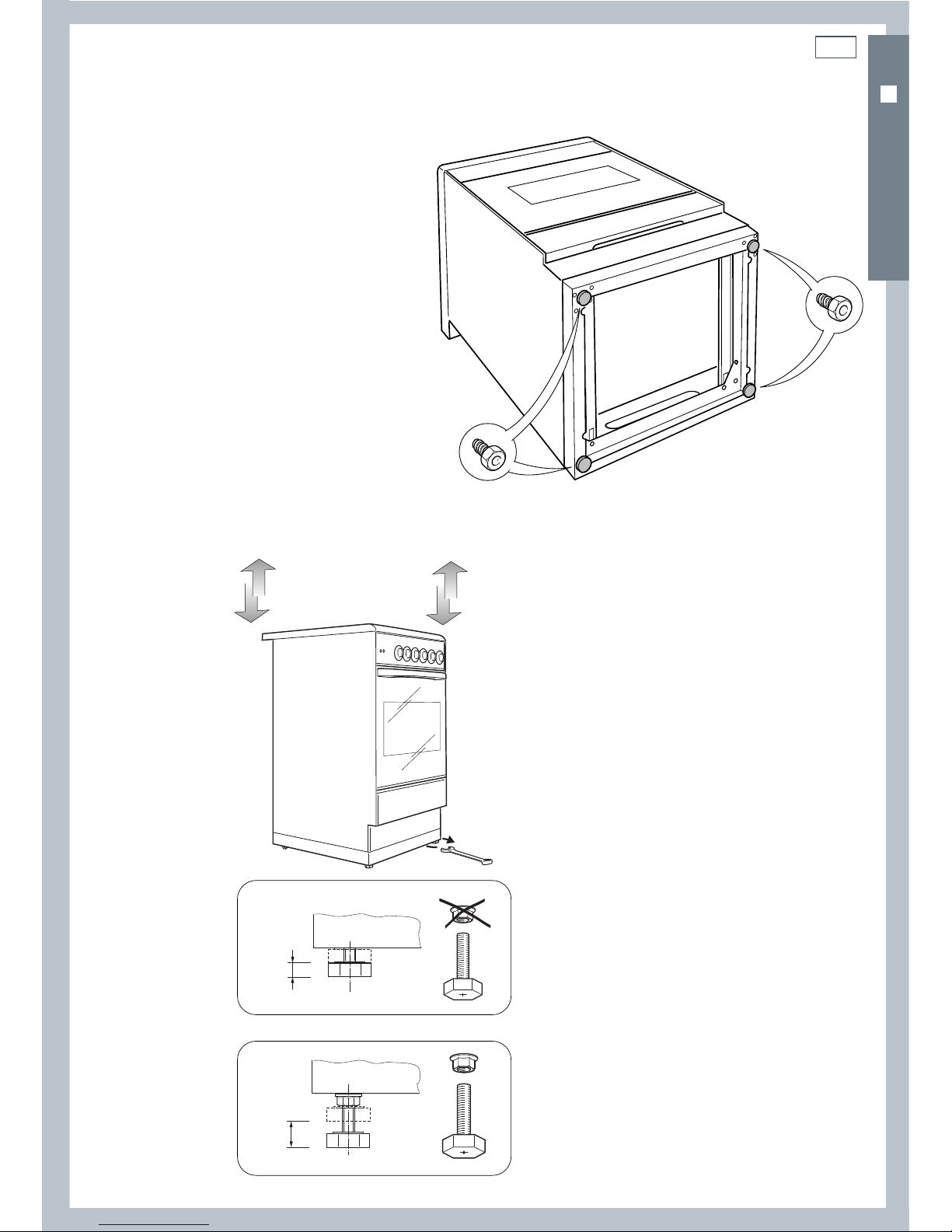
Levelling the cooker
Important!
Using the supplied adjustable feet is
MANDATORY. For safety reasons and to
ensure adequate ventilation, the cooker
chassis MUST NOT sit directly on the floor, a
plinth, or other support surface.
To fit the adjustable feet:
1
Rest the rear of the cooker on a piece of
packaging, exposing the base for fitting
the feet.
2
Screw the four feet to the cooker.
3
Stand the cooker and level it by
screwing or unscrewing the feet
with an adjustable spanner. Use the
supplied nuts if necessary, see Figs. 2b
and 2c.
Fig. 2a Fitting the adjustable feet
(supplied with the cooker in the feet kit)
0
+ 8
mm
+ 8 mm
+ 15 mm
Fig. 2c Use the supplied nuts for height
adjustments between 8 and 15 mm.
Fig. 2b Do not use the supplied nuts for height
adjustments between 0 and 8 mm.
OR60 MODELS
8
Installation instructions
OR60 MODELS
365
235
600 mm
min 105
max 120
0
+ 15
+ 15
(Cavity width)
1
2
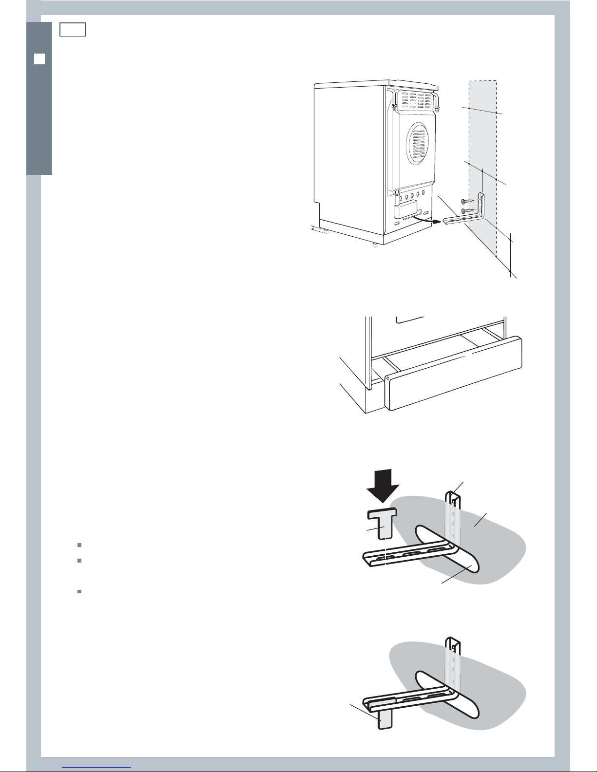
Fitting the anti-tilt bracket
Important!
To restrain the appliance and prevent it tipping
accidentally, fit a bracket to its rear to fix it
securely to the wall. Make sure you also fit the
supplied lock pin to the anti-tilt bracket.
To fit the anti-tilt bracket:
1
After you have located where the cooker
is to be positioned, mark on the wall the
place where the two screws of the anti-tilt
bracket have to be fitted. Please follow the
indications given in Fig. 3a.
2
Drill two 8 mm diameter holes in the wall
and insert the plastic plugs supplied.
Important!
Before drilling the holes, check that you will not
damage any pipes or electrical wires.
3
Loosely attach the anti-tilt bracket with the
two screws supplied.
4
Move the cooker to the wall and adjust the
height of the anti-tilt bracket so that it can
engage in the slot on the cooker’s back, as
shown in Fig.3a.
5
Tighten the screws attaching the anti-tilt
bracket.
6
Push the cooker against the wall so that the
anti-tilt bracket is fully inserted in the slot
on the cooker’s back.
7
Access the bracket and fit the lock pin:
Remove the drawer (Fig. 3b).
Fit the lock pin through the bracket,
as shown (Fig.3c).
Refit the drawer.
Fig. 3a Fitting the anti-tilt bracket
Fig. 3c Fitting the lock pin through the bracket
Anti-tilt bracket
attached on the
rear wall
Cooker’s
back
Lock pin
Slot on the
cooker’s back
Lock pin
correctly tted
Fig. 3b Removing the drawer

9
Installation instructions
OR60 MODELS
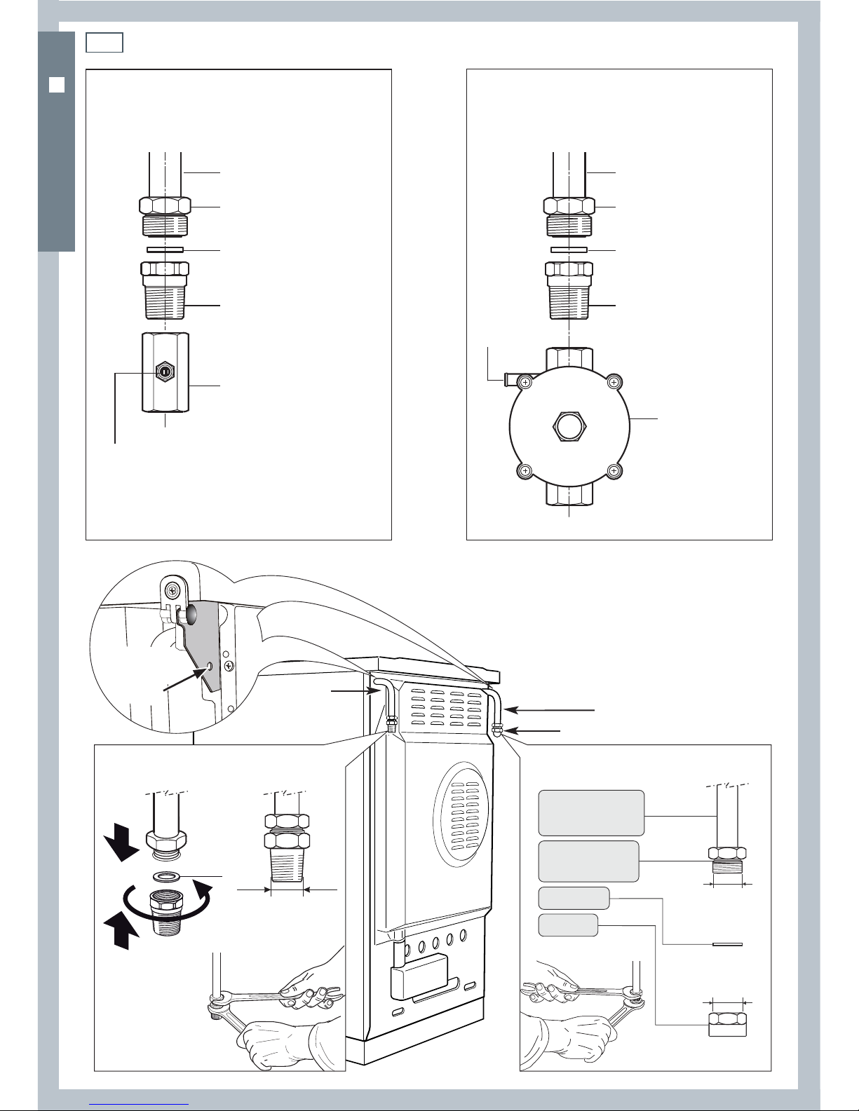
Connecting the cooker to the gas supply
The gas connection must be carried out by an authorised person according to the relevant
standards.
Before connecting the appliance to the gas main, mount the brass conical adaptor onto the gas
inlet pipe, upon which the washer has been placed (see Fig.s 4-5 following).
Conical adaptor and washer are supplied with the appliance (packed with conversion kit for use
with Natural gas or LPG).
This appliance is suitable for use with Natural gas or LPG. (Check the “gas type” sticker attached
to the appliance).
For Natural gas, connect the gas supply to the gas pressure regulator which is supplied with the
appliance (Fig.5). Adjust the regulator to obtain a test point pressure of 1 kPa with the two semirapid burners operating at the maximum.
For LPG, connect the gas supply to the test point adaptor which is supplied with the appliance
(Fig.4). Ensure that the supply pressure is regulated to 2.75 kPa.
The connection must be made at the rear of appliance (left or right); the pipe is not to cross the
cooker.
Close off the unused inlet with the cap and sealing washer supplied (Fig. 6).
IMPORTANT: Use two spanners to tighten or loosen the connecting pipe (Fig.6).
Installation with a flexible hose assembly
If this appliance has to be installed with a hose assembly, the installer shall refer to the network
operator or gas supplier for confirmation of the gas type, if in doubt.
When used with a flexible hose, the connector on the wall should be between 450 mm to 500
mm from the floor and 200 mm to 300 mm from the left-hand side of the appliance as viewed
from the front. The hose connection on the appliance shall face downwards.
It is important that the hose does not come in contact with the metal of the appliance and is
secured as per appropriate gas installation codes. A chain 80% of the length of the flexible gas
hose must be used to prevent stress being applied to the hose. The chain should be attached
securely to the product where shown (see Fig.6), and on the wall.
Flexible hose assemblies should be AS/NZS 1869 Class B or Class D certified. The thread
connection shall be Rp ½ ” (ISO 7-1) male.
Important!
After connection the installer must check that the hose is not kinked, subjected to abrasion or permanently
deformed. The installer must check also that the hose is not near or in contact with any hot surfaces.
The hose assembly shall be as short as practicable and comply with relevant AS/NZS 5601.1
requirements.
10
Installation instructions
OR60 MODELS
Chain
security
hole
Left gas
inlet pipe
Washer
Rp ½”
(ISO 7-1)
male
G ½”
(ISO 228-1)
male
G ½”
(ISO 228-1)
female
Fitting the brass conical adaptor
Fitting the cap on the
inlet pipe terminal not used
Right gas inlet pipe
Cap
Cooker manifold
(right or left
inlet pipe)
Manifold male
pipe tting
(#) Already tted on the
right or left inlet pipe
Washer (#)
Cap (#)
Gas connection for
LPG
Gas connection for
NATURAL GAS
Gas inlet pipe
Nipple
Washer
Brass conical adaptor
(Thread tight: use
suitable seal)
Gas inlet pipe
Nipple
Washer
Brass conical adaptor
(Thread tight: use
suitable seal)
Gas pressure
regulator
Test point adaptor
Test
point
Test
point
Fig. 5 Natural gas connectionFig. 4 LPG connection
Fig. 6 Gas supply inlet

11
Installation instructions
OR60 MODELS
Leak-testing and flame-testing the cooker
After installing the freestanding cooker and connecting the gas supply:
1
Using a suitable leak detection fluid solution, check each gas connection one at a time by
brushing the solution over the connection.
The presence of bubbles will indicate a leak. If there is a leak, tighten the fitting and then
recheck for leaks.
Important!
Do not use a naked flame to test for leaks.
2
Adjust the test point pressure or supply pressure to the value that is appropriate for the gas
type.
3
Test the operation of the appliance:
Turn on the appliance gas controls and light each burner individually and in combination.
Check for a well-defined blue flame without any yellow tipping. If any abnormality is
evident, then check that the burner cap is located properly and the injector nipple is
aligned correctly.
Check the minimum burner setting by quickly rotating the gas control dial from the
maximum to the minimum position. The flame must not go out. If you need to adjust the
setting, see ‘Adjusting the minimum burner setting’ following.
4
If satisfacfory performance cannot be obtained, the installer shall check the installation and
notify the local gas supply authority for a gas supply problem, or if it is an appliance problem,
our Customer Service Centre should be called to obtain the nearest authorized Service Agent.
12
Converting to a different gas type
This appliance is suitable for use with Natural gas or LPG (check the “gas type” sticker attached
to the appliance). To convert from one gas type to another, you need to replace the injectors,
and then adjust the minimum burning setting.
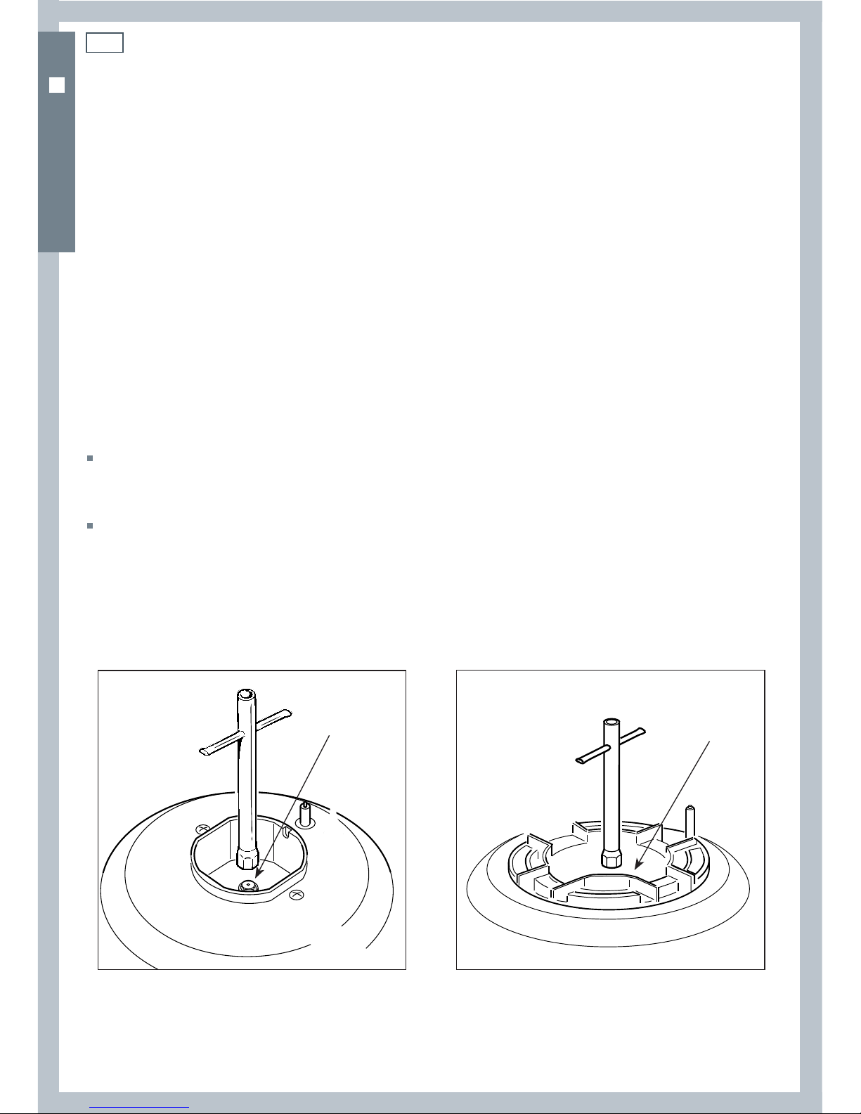
Replacing the injectors
1
Remove the trivets and burners from the cooktop.
2
Using a spanner, remove the injectors (shown in Figs. 7-8 following) and replace them with ones
according to the gas type (see the ‘Table for the choice of injectors’).
3
Fix the warning label (supplied with the conversion kit) at the back of the cooker, near the gas
inlet connections. This label states that the gas cooktop has been converted for use with LPG/
Natural gas.
Adjusting the minimum burner setting
4
Follow the instructions, ‘Adjusting the minimum burner setting’.
Important!
If you are converting the cooker from Natural gas to LPG,remove the gas pressure regulator
before connecting the cooker to the gas supply and replace with the test point adaptor supplied
with the conversion kit.
If you are converting the cooker from LPG to Natural gas, remove the test point adaptor before
connecting the cooker to the gas supply and replace with the gas pressure regulator supplied
with the conversion kit.
Notes:
- The burners are designed so that regulation of primary air is not required.
Installation instructions
Injector
Fig. 7 Auxiliary and semi-rapid burners Fig. 8 Triple-ring wok burner
Injector
OR60 MODELS
13
Installation instructions
OR60 MODELS
Adjusting the minimum burner setting
Check whether the flame spreads to all burner ports when the burner is lit with the gas valve set
to the minimum position. If some ports do not light, increase the minimum gas rate setting.
Check whether the burner remains lit even when the gas valve is turned quickly from the
maximum to the minimum position. If the burner does not remain lit, increase the minimum gas
rate setting.
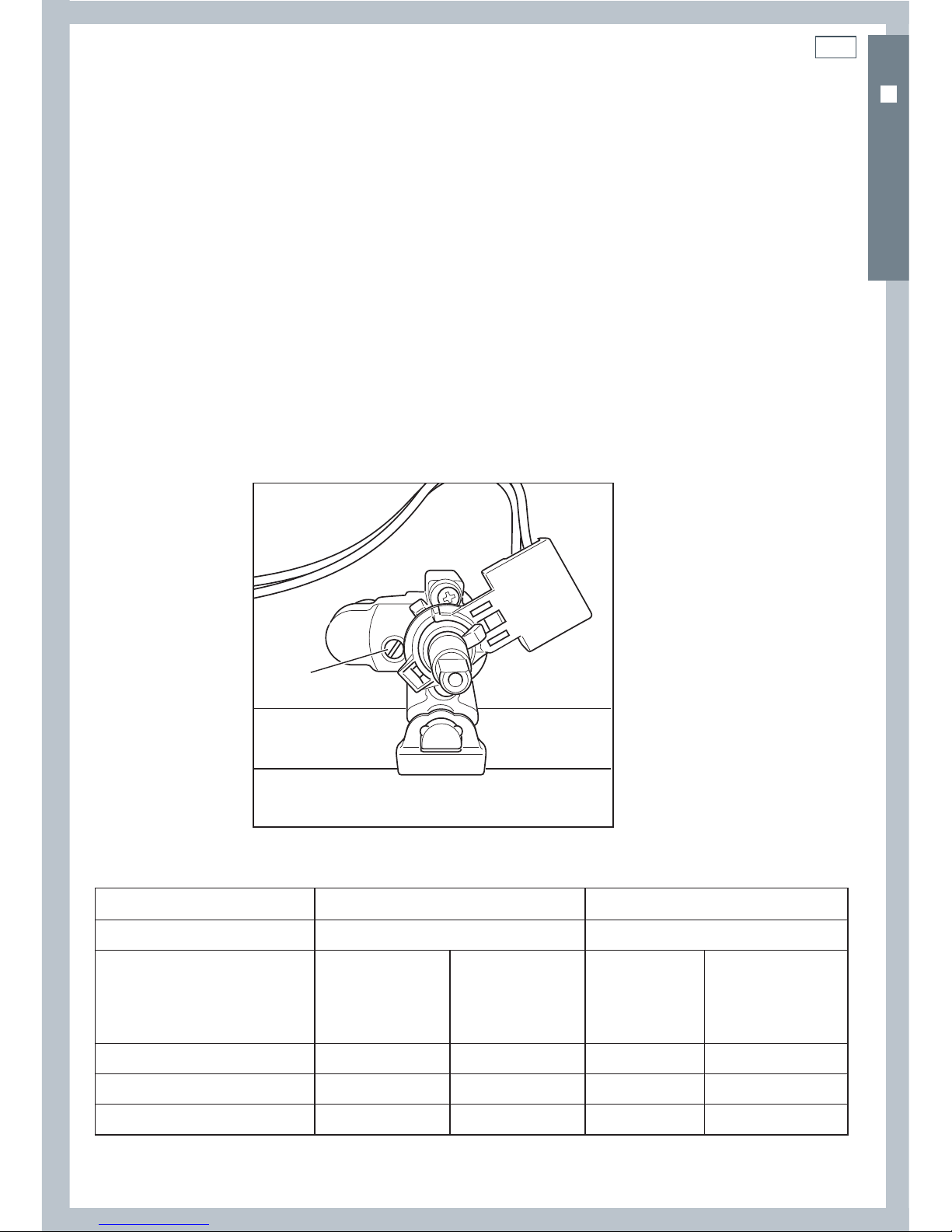
To adjust the minimum gas rate setting:
1
Turn on the burner.
2
Turn the valve to the MINIMUM position.
3
Take off the knob.
4
Using a small flat screwdriver, turn the screw (see Fig. 9) to the correct regulation.
Note: for LPG, the regulation screw is normally tightened up.
Table for the choice of injectors
Natural gas LPG
Test Point Pressure [kPa] 1.0 2.75
BURNER
Injector
Orifice Dia.
[mm]
Gas
Consumption
[MJ/h]
Injector
Orifice Dia.
[mm]
Gas
Consumption
[MJ/h]
Auxiliary
0.85 3.60 0.53 3.60
Semi-rapid
1.12 6.30 0.70 6.30
Triple-ring wok
1.60 12.70 0.95 11.90
Fig. 9 Adjusting the
minimum burner setting
regulation screw
regulation screw
14
1a
2a
3a
4a
5a
1
2
3
4
5
LF
C
G
S
CF
TL
V
TM
S1
A
PA
F1
T
NL
M
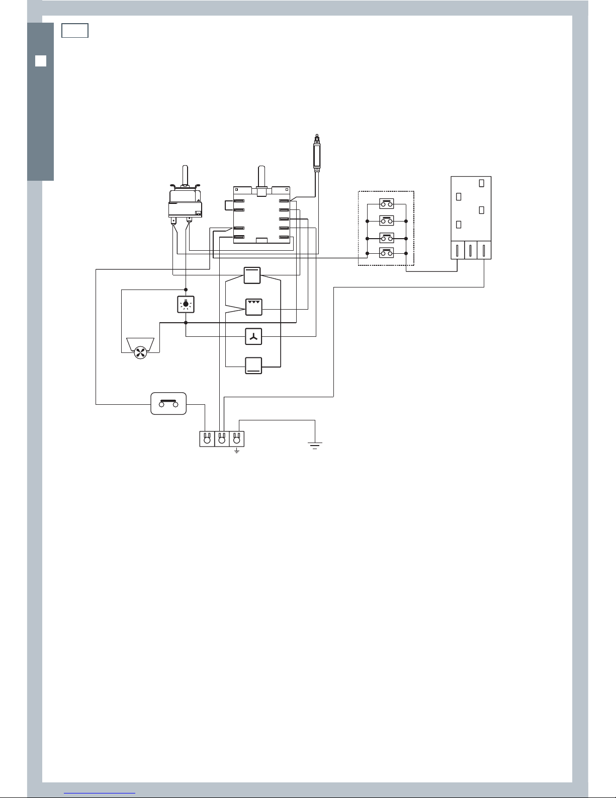
ELECTRIC DIAGRAM KEY
F1 Oven switch
TM Oven thermostat
TL Thermal overload
LF Oven lamp
C Top element
G Grill element
S Bottom element
V Fan motor
CF Cooling fan motor
S1 Thermostat pilot lamp
PA Ignition switches group
A Ignition coil
M Terminal block
T Earth connection
Installation instructions
Wiring diagram
OR60 MODELS
Fig. 10 Wiring diagram

15
 Loading...