

Fisher & Paykel Dryer Installation Instructions Manual
\
Dryer
installation instructions and
User Guide US CA
Secadora
Instrucciones de Instalaci6n y
Guia del Usuario ES
New Zealand f_,L_stralla USA Canada Eur,- pe Asia P,sclfic
_\_ _g_o.RNING: For your safety the iaf_rmat_oa ia
th_s manual must be fo[h_wed to miaimize the risk
of fire or exp_osioa or to preve_lt property damage,
perso=a[ bliury or death°
-- Do aot store or use gasohne or other _ammaWe vapors
aad liquids b_ the vida_ty of aay other app[iaaceo
-- WHAT TO DO IIFYOU SMELL GAS
÷ Do aot try to _ight aay app_iaaceo
° Do _mt touch aay dectricaJ switch} d.o aot use aay
phoae ir:_your: bui_di_lgo
÷ CJear the room, bui_diag or area of a[[ occupaatso
° Immediately call your gas supplier _}om a _dghbor's
* i[f you caanot reach your g_s supplier, ca[_ the fire
--i[asta[[atioa aad service mast be performed by a
qualified b_sta[[er, service ageacy or the gas supp[iero
Y}e 6ove_>o_' of CaIifo_'_da to pLsbIisb a !ist of sLsbsta_'ces k_"ow_'tto the state of
([a/ifo_'tia to ca_,sse ca_'_ce_'0_' _'ep_'od_sctive ha_'m a_d _'eq<si_'es b_{sieesses to wa_e
<:Llstome_s of pote_ tia[ e)4pos_'es to s/,_<:}'_s_bsta_"ces
(_as app[ a_'ces co_ta[_" o_' p_'od .see s_sbsta_"ces, w}_[ h ca_ <a_sse deat}b o_' scabious
i[b'ess a_"d w}_ h a_'e k_ ow_" to the State of Ca_ifo_'_da to ca_,sse cat"eel', bi_'th
defect% o_ othe_' _'ep_'od_sct[ve ha_'mo lb _'ed<s<e t}_e _[sk f_'o_r,substa_'ces i_ f_se}
0_ f_om fl_e[ <e"_b_st o_ , make s ._'e this appIia_"ce is _staI/ed, epe_'ated, a_d
_>_)h_ah_ed ac o_'di_% to the may_.,_fa<%_'e_s b"_st_u<tioy_s
Contents
Dryer Safety
Important Safety Instructions
Warranty
Installation Instructions
Installer Responsibilities, Location Requirements
Dimensions
Exhausting
Maximum Length of Exhaust Duct
Alternative Exhaust Directions
ExhaustVenting
Installation
Grounding Instructions
Electrical Requirements
GasRequirements
Level Machine, Final Installation Check List
Features
Operating Instructions
Reversing the Door
Quick Start / Using Your Dryer
Care Labels
Drying Spedal Items
Other Features
Cleaning
Trouble Shooting
Limited Warranty
6
8
9
10
12
13
15
17
19
2O
21
22
25
28
29
30
32
33
38
39
41
42
44
46
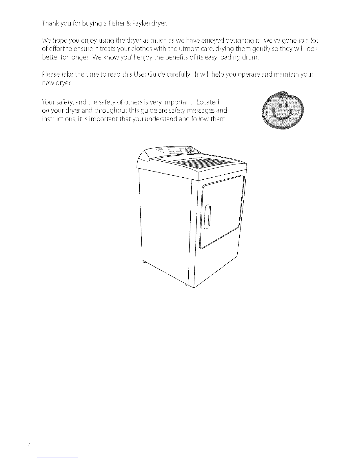
Thankyou for buying a Fisher& Paykeldryer.
We hope you enjoy using the dryer as much aswe haveenjoyed designing it. We'vegone to a lot
of effort to ensure it treats your clothes with the utmost care,drying them gently so they will look
better for longer. We know you'll enjoy the benefits of its easyloading drum.
Pleasetake the time to read this UserGuide carefully. It will help you operate and maintain your
new dryer.
Your safety,and the safety of others isvery important. Located
or] your dryer and throughout this guide are safety messagesand
instructions; it isimportant that you understand and follow them.
Dryer Safety
'Toreduce 'therisk of fire, electric shock, or injury 'to persons, read
the iMPORTANTSAFETYiNSTRUCTiONSbefore operatin 9 this
Failureto follow to do so can result in death or electric shock°
Symbols
Symbols will be used in this Guide to highlight when extra care isrequired. Abide by these at all
times to ensure you and your family are not harmed while operating your dryer.
It isimportant to always act with caution and usecommon sense when operating your dryer. Use
only as perinstructed by the UserGuide.
This isthe safety alert symbol. This symbol alerts you to hazardsthat carl kill
or hurt you and others.
The safety alert symbol and the word DANGERor WARNINGwill precede all
safety messages. These words mean:
Youcan be killed or seriously injured ifyou don't
immediate[ 2 follow instructions.
Youcan be killed or seriously injured ifyou don't follow
[nstructionso
All safety messageswill identify the hazard,tell you how to reduce the chance of injury, and
tell you what carl happen if the instructions are not followed.
Important Safety Instructions
Emectric Shock Hazard
Follow the safety precautk_ns outlined in this User Guide°
Failureto do so can result in death or electric shock,
Safety Precautions
a Readall instructions carefully before using this dryer.
• Usethis dryer only for its intended purpose as described in this UserGuide.
• To minimize the possibility of electric shock, unplug this dryer from the power supply or
disconnect the dryer at the household distribution par]el (by removing the fuse or switching off
the circuit breaker) before attempting any user mair]ter]ance or cleaning.
• [r]stallation must conform with local codes, or in absence of localcodes,with the National FuelGas
Code,ANSIZ223.l/NFPA 54 or the Canadian NaturalGasand Propane [r]stallatior] Code,CSAB149.1.
• [r]stallationsand service must be performed by a qualified or licensed contractor, plumber or
gasfitter qualified or licensedby the state, province, or region where this appliance is being installed.
This dryer must be properly installed and located in accordance with the Ir]stallation Instructions
before it is used.
• This dryer,when installed, must be electrically grounded in accordance with local codes,or in the
absence of local codes,with the National Electrical Code,ANSI/NFPA70, or the Canadian Electrical
Code,CSAC22.1.
Do not install or store the dryer where it will be exposed to water or exposed to the weather.
Connect to aproperly protected, rated and sized power supply circuit to avoid electrical overload.
• Do not repair or replace any part of the appliance or attempt any servicing, unless specifically
recommended in the published user repair instructions that you understand and have the skills to
carryout.
When discor]r]ecting the dryer, pull by the plug rather than the cord or junction of the cord plug,
to avoid damage to the cord or junction of the cord plug.
Makesure the cord is located so that it will not be stepped or],tripped over or otherwise subject
to stress or damage.
Do not tamper with the controls.
Note:Turning the CycleSelector knob to an OFF position does NOTdisconnect the appliance
from the power supply.
Do not operate this dryer if it isdamaged, malfur]ctior]ing, partially disassembled or has missing
or broker] parts, including a damaged cord or plug.
This dryer must be directly connected to an approved fixed electrical outlet. Itcar]not be
plugged into an extension cord or an adaptor plug.
Important Safety Instructions
Only dry fabrics that have been washed with water°
Do not useheat to dry articles containing foam rubber or simi[dy
textured rubber.like materia[so Dry on the Fluff cyc[eo
A clothes dryer produces combustible lint and must be exhausted
outdoors, Takecare to prevent'the accumulation of lint around
the exhaust opening and in the surrounding area,
Failureto follow these instructions can result in death or persona[
injury,
To Reduce the Risk of Fire in a Tumble Dryer the Following Should
be Observed:
a Do not place items in atumble dryer that havepreviously beer] cleaned in, washed in, soaked
in, or spot cleaned with flammable liquids or solids. They are a fire or explosion hazard. Highly
flammable substancescommonly used in domestic environments include acetone, denatured
alcohol, gasoline, kerosene,some brands of spot removers and dry cleaning solvents, turpentine,
waxes,wax removers,vegetable oi1,fish oi1,massageoi1,and cooking oik
Do not leave hot oi1affected items in a pile or stack. This carl prevent heat from escaping and carl
create afire hazard. 0i1 affected items carl ignite spontaneously, especially when exposed to heat
sources such asatumble dryer. The items become warm causing an oxidation reaction in the oik
This oxidation creates heat. If the heat cannot escapethe items carl become hot enough to catch
fire.
Donot useheatto dryitemscontainingrubber,foamrubber,plasticor similarmaterials,(suchas
paddedbras,bathmats,rugs,bibs,babypants,plasticbags,pillowsetc),asthesematerialsmight
meltor burr]. Somerubbermaterialswhenheatedcarlundercertaincircumstancesproducefire
byspontaneouscombustion. Dryonlyor]the FLUFFcycle.
Unlessspecificallyrecommendedbytheirmanufacturer,do not usefabricsoftenersor similar
productsin a tumbledryer.
Donot storeor usegasolineorotherflammablegasesand liquidsnearthisoranyother
appliance.
Keeptheareaaroundthe exhaustopening andadjacentsurroundingareasfreefrom the
accumulationofcombustiblematerialssuchaslint,paper,rags,chemicalsetc.
Donot storeany itemsthat mayburr]or melt (suchaspapermaterials,plasticsor plastic
containers,etc) nextto thedryer.
Clear]the lintfilter eachtimeyou usethedryer,beforeoraftereachload.
Important Safety Instructions
a The dryer must be exhausted to the outside. Carefully follow the venting details in the Ir]stallation
Instructions.
Keepthe floor around your dryer clearsand dry to reduce the possibility of slipping.
Ifyour dryer is rur]r]ing and you want to unload or add clothes, open the dryer door.
Do not reach into the appliance if the drum is moving.
Close supervision is necessary if this dryer is usednear children. Do not allow children to play
inside, around or with this dryer or any other appliance.
Neverclimb ors,climb into, or stand orsthe dryer top or drum.
Undergarments that contain metal reinforcements should not be placed directly in the dryer.
Damage to the dryer carl result if the metal reinforcements come loose during drying. If you wish
to dry these items use a drying rack (available asan optional accessory refer to page 9).
The interior of the appliance and exhaust duct should be cleaned periodically by quali_ed service
personnel.
When discarding or storing old clothes dryer, remove the door.
Warranty
Your dryer hasbeersmade to the highest standards. Yearsof development and rigorous testing
ensure that you have bought a world classproduct, in the unlikely event that a problem should
occur, referto the Limited Warranty section at the back of this Guide (referto page 46).
Ifyou havea problem with your dryer refer to our troubleshooting section. If your problem is not
referenced, pleasealways contact your Fisher& PaykelAuthorized Service Agent or our Customer
CareCenter (Toll Free ] 888 9 FNPUSA(1 888 9 367 872)) rather than attempting to _xit yourselfl
nstallation Instructions
6 o Risk of fire
• Clothes dryer installation must be performed by a qualified installer.
• Install the clothes dryer according to the manufacturer's instructions and local codes.
Do not install a clothes dryer with flexible plastic venting materials. If flexible metal (fOil type)
duct isinstalled, it must be of a specific type identified bythe appliance manufacturer assuitable
for usewith clothes dryers. Flexible venting materials are known to collapse, be easilycrushed,
and trap lint These conditions will obstruct clothes dryer airflow and increase the risk of fire.
To reduce the riskof sever injury or death, follow all installation instructions.
Savethese instructions
Read the Important Safety Instructions on pages 6 - 8 before you start
installing your dryer.
Check to make sure you haveall the tools and parts necessary to correctly install this appliance.
Tools Required
]/4"nut driver or socket wrench
Phillips screwdriver
• Flat blade screwdriver
• Adjustable wrench 200or 250mm (8"or 10")for gas cormections (gasmodels only)
• Pipejoint compound (pipe dope or tape) for gas pipe cormections that is resistant to LPPropane,
Butanea nd Natural Gas(gasdryer only)
Leve
• CauIk_nggunandcompound<for_nstaU_ngnewexhaustvent)
6loves
" Safetyglasses
,, Knife
Duct tape
Accessories
" Mobile Home Installation Kit PartNo 14 D346 33
DryingRackKitPartNoWE1M396
" Cover Plate to Rearof Cabinet Kit Part No WE]M454
Seethe rating plate in the door opening to identify the appropriate kit number (Mxx) for
conversion to LPor natural gas.
Parts Needed
Check with local codes and readelectrical, gas and venting requirements before purchasing parts.
Ifyou need to purchase apower supply cord kit or power supply cable,they must meet the
requirements or] page 23.
ii!i!i!i!i!i!i!i!i!i!i!i!i!i!i!i!i!i!i!
To the Installer
The correct installation of the dryer isyour responsibility.
Besureyou read the following instructions carefully before you start to install the dryer. These
instructions should be left with the home owner for future reference.
It is Your Responsibility to:
• Observe all governing codes and ordinances.
• Check code requirements. Some codes limit or do not permit installation of clothes dryers in
garages, closets, mobile homes or sleeping quarters. Contact your local building inspector.
• Adhere to these installation instructions.
• Allow for spacing requirements with side by side installations (refer page ]]).
• Makesure you have all items necessaryfor correct installation.
• Properly install the dryer.
• Contact a qualified installer asappropriate to ensure that the electrical and gasinstallation meets
all national and local codes and ordinances. (Seepage 6).
Location Requirements
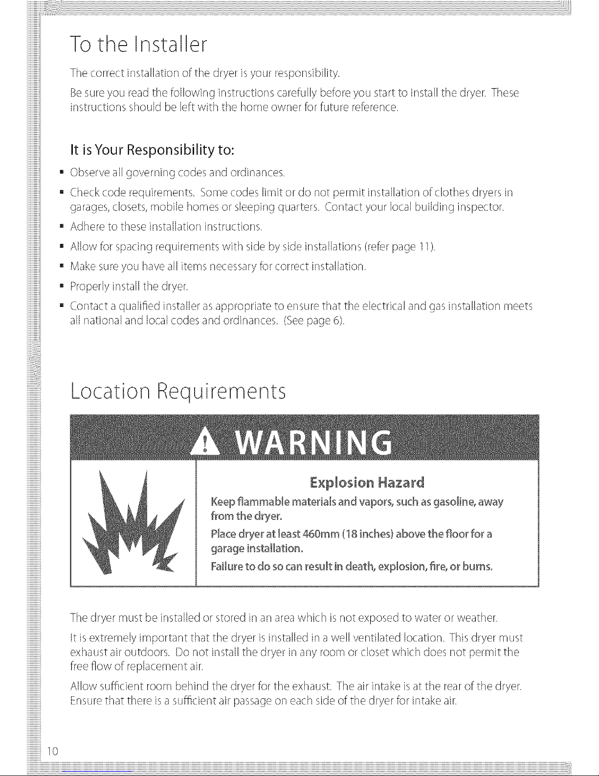
£xIIosio_ Hazard
KeeDflammable materials and vaDorg such asgasoline_away
from the dryer°
Placedrier at least @aOmm(1t inches) above the floor for a
Failureto do so can result in death, e×plosion, £re,or burns°
iiiiiiiiiiiiiiiiiiiiiiiiiiiiiii
iiiiiiiiiiiiiiiiiiiiiiiiiiiiiii
iiiiiiiiiiiiiii
iiiiiiiiiiiiiii
iiiii
!i!i!i!i!i!i!i!i!i!i!i!i!i!i!i!
iiiiiiii
!i!i!i!i!i!i!i!i!i!i!i!i!i!i!i!
iiiiiiii
iiiiiiiiiiiiiiiiiiiiiiiiiiiiiii
iiiiiiiii
!!!!!!10
The dryer must be installed or stored in an areawhich is not exposed to water or weather.
It isextremely important that the dryer is installed in a well ventilated location. This dryer must
exhaust air outdoors. Do not install the dryer in any room or closet which does not permit the
free flow of replacement air.
Allow sufficient room behind the dryer for the exhaust. The air intake isat the rear of the dryer.
Ensurethat there isa sufficient air passage or] each side of the dryer for intake air.
Location Requirements
The area in which the dryer is located must be
kept clear and free from combustible materials,
gasoline and other flammable vapors and liquids.
A dryer produces combustible lint so the area
around the dryer must be cleaned regularly to
keep it free of lint
Alcove or Closet Installation
When installing a dryer in aclose't/alcove it must be
exhausted to the outdoors° No other fuel burning appliance
canbe insta[bd in the same closet or alcoveo
iiiiiiiiiiiiii
iiiiiiiiiiiiii
iiiiiiiiiiiiiiiii
iiiiiiiiiiiiiiiii
iiiiiiiiiiiiiiiiiiii
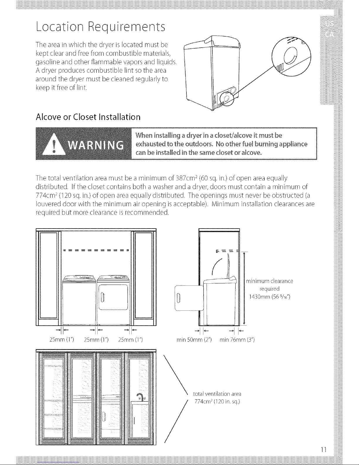
The total ventilation area must be a minimum of 387cm2(60 sq. in.)of open area equally
distributed. Ifthe closet contains both a washer and a dryer, doors must contain a minimum of
774cm2(120sq.in.) of open area equally distributed. The openings must never be obstructed (a
Iouvered door with the minimum air oper]ing isacceptable). Minimum installation clearances are
required but more clearance is recommended.
"ll--
25mm (1")25mm (1") 25mm (1") min 50mm (2")
minimum clearance
required
1430mm (56s/_,,)
<-.
min 76ram (Y)
total ventilation area
774cm2(120in.sq.)
11
Location Requirements
Bathroom or Bedroom Installation
• The Dryer MUSTbe vented to the outdoors. SeeEXHAUSTinformation.
Dimensions
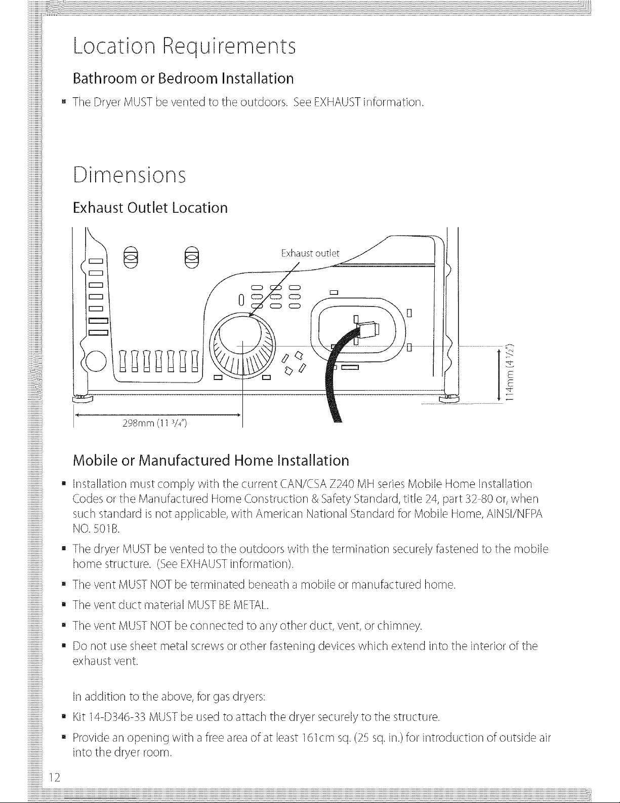
Exhaust Outlet Location
/
Exhaust outlet . / _']/
_ CD CD -- _,
l;, .............
Mobile or Manufactured Home Installation
• Installation must comply with the current CAN/CSAZ240 MH series Mobile Home Installation
Codes or the Manufactured Home Construction & Safety Standard,title 24, part 32 80 or, when
such standard is not applicable, with American National Standard for Mobile Home, AINSI/NFPA
NO.501B.
The dryer MUSTbevented to the outdoors with the termination securely fastened to the mobile
home structure. (SeeEXHAUSTinformation).
The vent MUSTNOTbe terminated beneath a mobile or manufactured home.
The vent duct material MUSTBEMETAL.
Thevent MUSTNOTbe connectedto anyother duct,vent,or chimney.
Donot usesheetmetalscrewsor otherfasteningdeviceswhichextendinto the interior of the
exhaustvent.
Inaddition to the above, for gasdryers:
Kit 14 D346 33 MUST be used to attach the dryer securely to the structure.
Provide an opening with afree area of at least ] 61cm sq.(;25sq.in.) for introduction of outside air
into the dryer room.
Exhausting
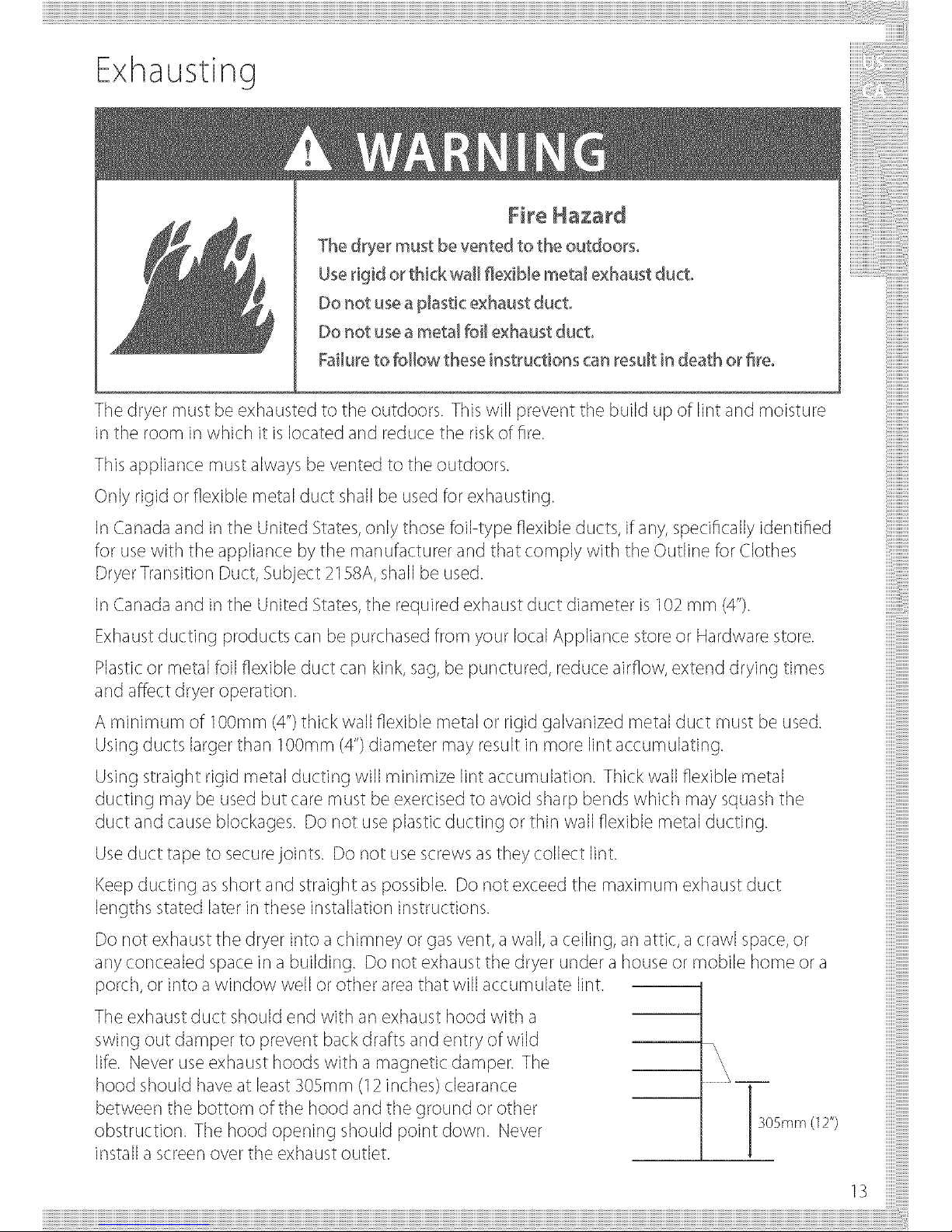
The dryer must be vented to the outdoors°
Userigid or thick wall flexible metal exhaust duct°
Do not usea plastic exhaust duct°
Do not usea me'tal foiJexhaust duct°
Failureto follow these instructions can _esu_tin death o_fire°
The dryer must be exhausted to the outdoors. This will prevent the build up of lint and moisture
in the room in which it is located and reduce the risk of fire.
This appliance must always be vented to the outdoors.
Only rigid or flexible metal duct shall be used for exhausting.
Jr]Canada and in the United States,only those foil type flexible ducts, if any, specifically identified
for usewith the appliance bythe manufacturer and that comply with the Outline for Clothes
DryerTransition Duct, Subject 2158A, shall be used.
Jr]Canada and in the United States,the required exhaust duct diameter is 102mm (4").
Exhaustducting products carl be purchased from your local Appliance storeor Hardware store.
Plasticor metal foil flexible duct carl kink, sag, be punctured, reduce airflow, extend drying times
and affect dryer operation.
A minimum of 100mm (4")thick wall flexible metal or rigid galvanized metal duct must be used.
Usingducts largerthan 100ram (4")diameter may result in more lint accumulating.
Using straight rigid metal ducting will minimize lint accumulation. Thick wall flexible metal
ducting may be used but care must be exercised to avoid sharp bends which may squashthe
duct and cause blockages. Do not use plastic ducting or thin wall flexible metal ducting.
Useduct tape to securejoints. Do not use screws as they collect lint.
Keepducting asshort and straight aspossible. Do not exceed the maximum exhaust duct
lengths stated later in these ir]sta%tion instructions.
Do not exhaust the dryer into a chimney or gas vent, awall, a ceiling, an attic, a crawl space,or
any concealed space in a building. Do not exhaust the dryer under a house or mobile home or a
porch, or into a window well or other area that will accumulate lint.
The exhaust duct should end with an exhaust hood with a
swing out damper to prevent back drafts and entry of wild
life. Never useexhaust hoods with a magnetic damper. The
hood should have at least305ram (12inches) clearance
between the bottom of the hood and the ground or other
obstruction. The hood opening should point down. Never
install a screen over the exhaust outlet.
305mm (12")
13
Exhausting
To reduce condensation, insulate any ducting which passesthrough unheated areas.
Slopethe duct gently downwards to the hood, to drain condensation and reduce lint build up.
Avoid sagor loops in the duct asthey may collect and store water and accumulate lint.
Beforeusing an existing exhaust duct system for a dryer ensure that:
No plastic or other potentially combustible duct or flexible metal foil ducting has beer] used.
The duct isnot pierced, kinked or crushed.
The duct does not exceed the maximum recommended length for the new dryer.
The exhaust hood damper opens and closesfreely and with sufficient movement.
Static pressure in the exhaust ducting does not exceed 3SOPa(1 inch of water column), or is not
lessthan 0 inches of water column (i.e.negative pressure),when measured with amanometer in
the first ] FOrum(6")of the duct, with the dryer running or] Fluff (no heat) setting.
The exhaust duct system meets all relevant local, state,province and national codes.
All ducting should be inspected and cleaned at least once a year to remove accumulated lint.
Frequently check that the damper or] the exhaust hood moves sufficiently and opens and shuts
freely.
Mobile Home Installations
AMobile Home Installation Kit isavailable (seeAccessories page _3and notes page 13).
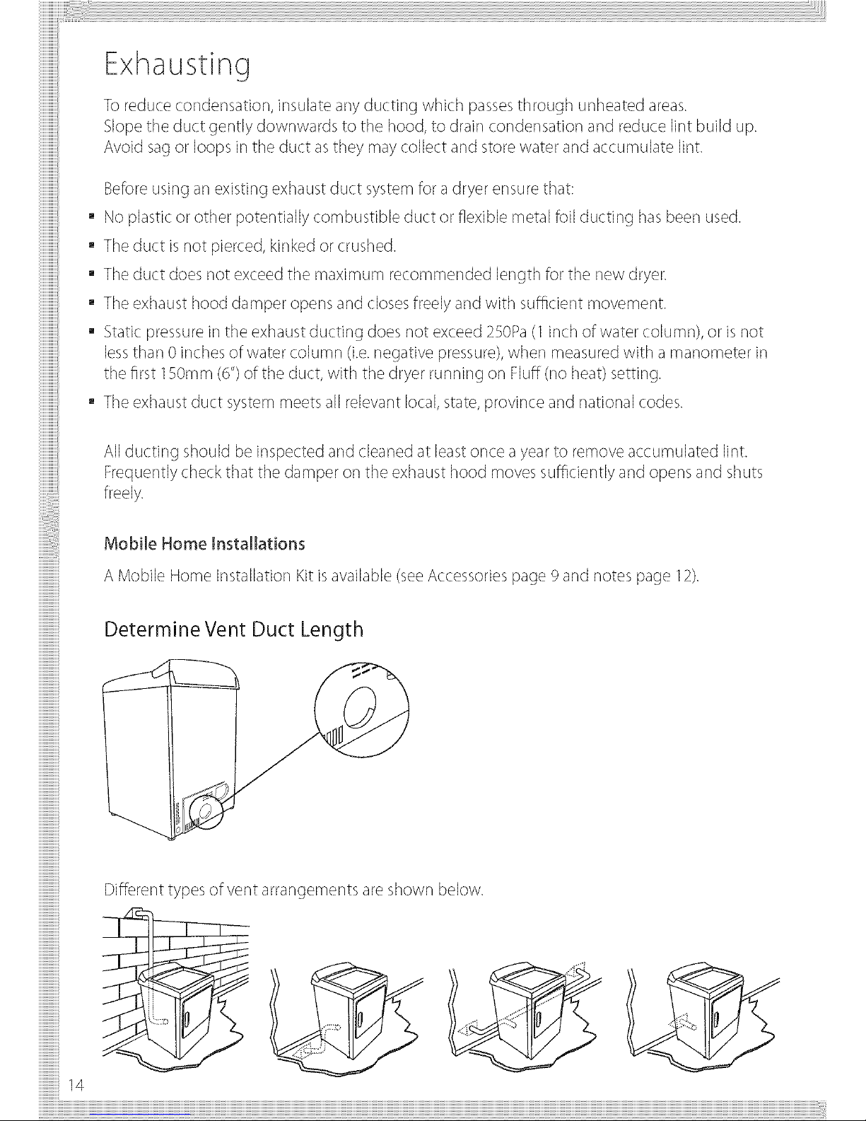
Determine Vent Duct Length
Different types of vent arrangements are shown below.
!!!!!!!!!!!!!!!i
iiiiiiiiiiiiiiiiiiiiiiiiiiiiiii
iiiiiiiiiiiiiiiiiiiiiiiiiiiiiii
!i!i!i!i!i!i!i!i!i!i!i!i!i!i!i!14
Exhausting
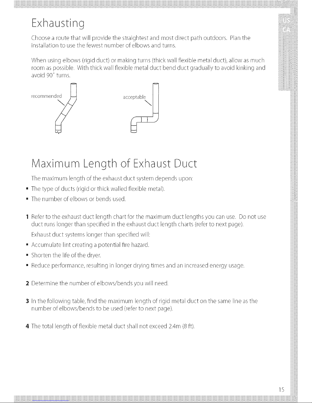
Choose a route that will provide the straightest and most direct path outdoors. Planthe
installation to use the fewest number of elbows and turns.
When using elbows (rigid duct) or making turns (thick wall flexible metal duct), allow as much
room aspossible. With thick wall flexible metal duct bend duct gradually to avoid kinking and
avoid 90° turns.
recommend_
iiiiiiiiiiiiii
iiiiiiiiiiiiii
iiiiiiiiiiiiiiiii
iiiiiiiiiiiiiiiii
iiiiiiiiiiiiiiiiiiii
Maximum Length of Exhaust Duct
The maximum length of the exhaust duct system depends upon:
a The type of ducts (rigid or thick walled flexible metal).
The number of elbows or bends used.
1 Refer to the exhaust duct length chart for the maximum duct lengths you carl use. Do not use
duct runs longer than specified in the exhaust duct length charts (refer to next page).
Exhaustduct systemslonger than specified will:
Accumulate lint creating a potential fire hazard.
Shorter] the life of the dryer.
Reduce performance, resulting in longer drying times and an increased energy usage.
;2Determine the number of elbows/bends you will need.
:3In the following table, find the maximum length of rigid metal duct or] the same line as the
number of elbows/bends to be used (refer to next page).
4 The total length of flexible metal duct shall not exceed 2.4m (8 ft).
15
Maximum Length of Exhaust Duct
!!!!!!!!!!!!!!!_
iiiiiiiiiiiiiiiiiiiiiiiiiiiiiii
iiiilililililililililililililil
iiiiiiiiiiiiiiiiiiiiiiiiiiiiiii
!i!i!i!i!i!i!i!i!i!i!i!i!i!i!i!16
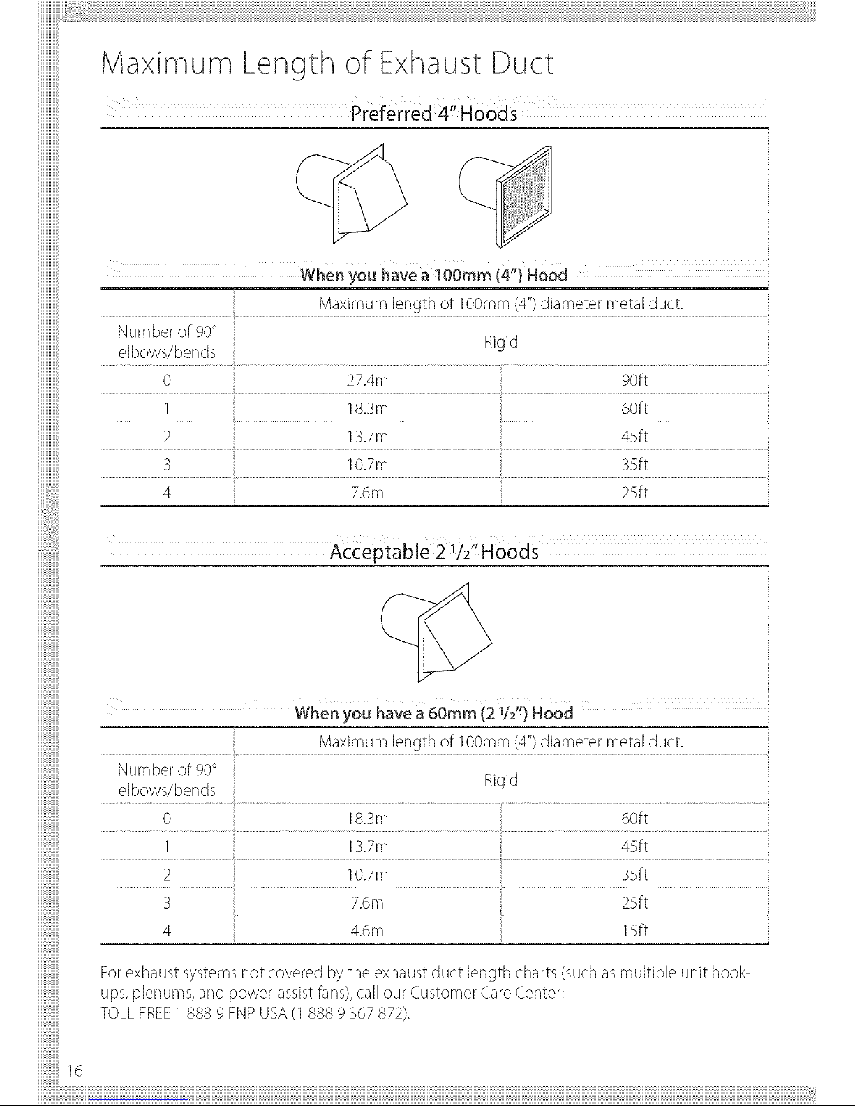
........... When you have a 60rnm (21/2") Hood ....
....... Maximum length of l OOmm(4")diameter metal duct.
Number of 90° Rigid
e!bows/bends..............................................................................................................................................................................
0 18.3m 60ft
......... I ................................. 13.7m ...... .......................45ft .........................................................................................
.................................2..................................................................................................................10.7m..............................................................................................................................................................BSft..................................................................................
3 .... 7.6m .... 25ft
4 4.6m 15ft
Forexhaust systems not covered by the exhaust duct length charts (such asmultiple unit hook
ups, plenums, and power assistfans),call our Customer CareCenter:
TOLLFREEI 888 9 FNPUSA(1888 9 367872).
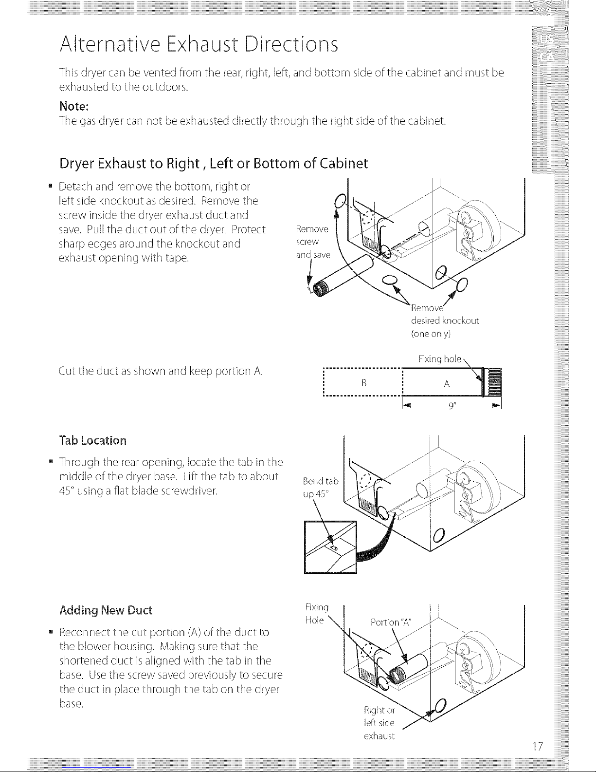
Alternative Exhaust Directions
This dryer car] be vented from the rear, right, left, and bottom sideof the cabinet and must be
exhausted to the outdoors.
Note:
The gas dryer car] not be exhausted directly through the right sideof the cabinet.
Dryer Exhaust to Right, Left or Bottom of Cabinet
a Detach and remove the bottom, right or
left side knockout asdesired. Remove the
screw inside the dryer exhaust duct and
save. Pull the duct out of the dryer. Protect
sharp edges around the knockout and
exhaust opening with tape.
Remove
screw
and save
iiiiiiiiiiiiii
iiiiiiiiiiiiii
iiiiiiiiiiiiiiiii
iiiiiiiiiiiiiiiii
iiiiiiiiiiiiiiiiiiii
Cut the duct as shown and keep portion A.
desired knockout
(oneonly)
Fixir/g hole
Tab Location
Through the rear opening, locate the tab in the
middle of the dryer base. Lift the tab to about
45° using afiat blade screwdriver.
Bendtab
UF
Adding New Duct
Reconnect the cut portion (A)of the duct to
the blower housing. Making sure that the
shortened duct is aligned with the tab in the
base. Use the screw saved previously to secure
the duct in place through the tab on the dryer
base.
Fixing I
Hole _1 P°rti°n"A"_
exhaust
17
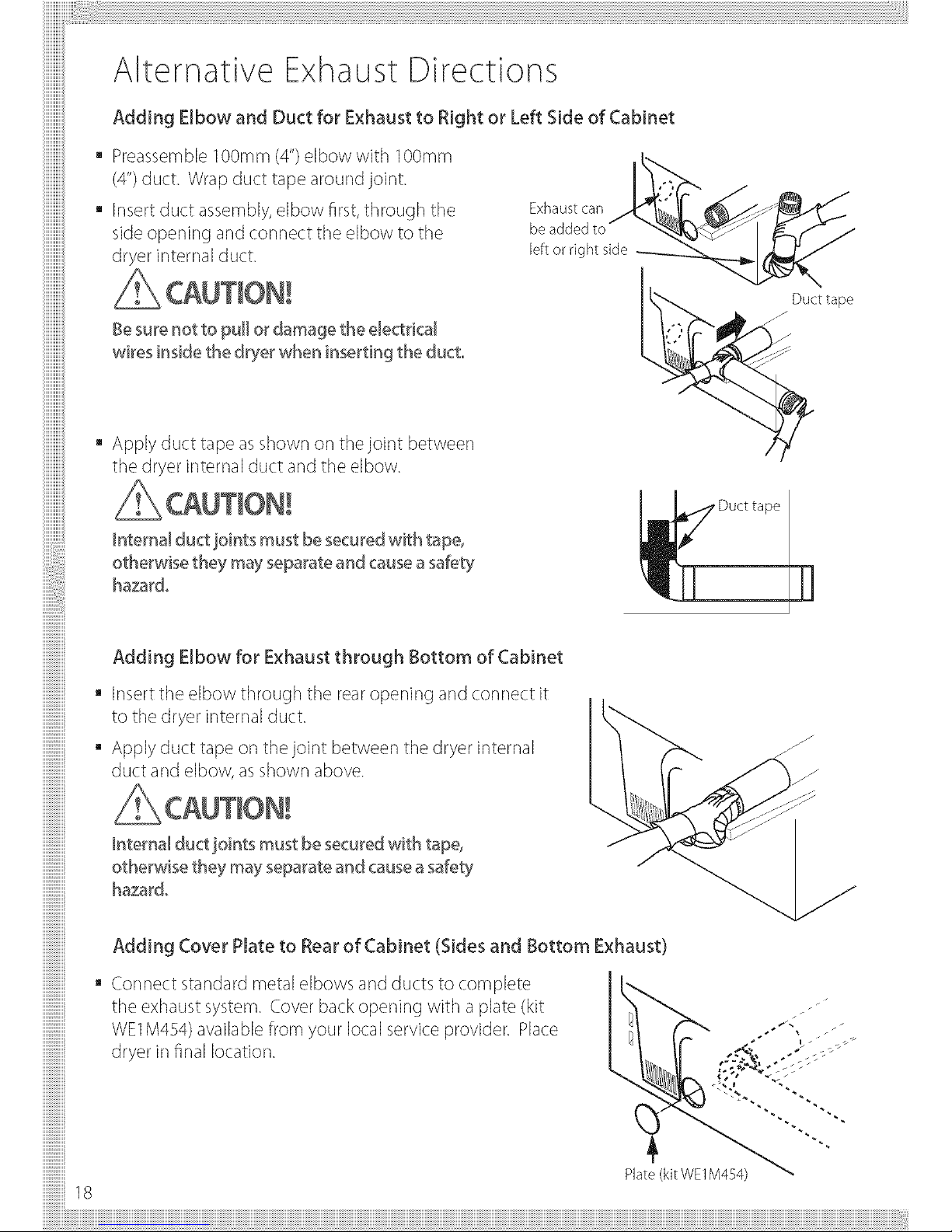
Alternative Exhaust Directions
Adding Elbow and Duct for Exhaust to Right or Left Side of Cabinet
mPreassemble ]OOmm (4")elbow with ]OOmm
(4")duct. Wrap duct tape around joint.
mInsert duct assembly,elbow frst, through the
side opening and connect the elbow to the
dryer internal duct.
Besurenot to pu[[ or damage the electrical
wires inside the dryer when inserting the duct°
• Apply duct tape as shown or] thejoint between
the dryer internal duct and the elbow.
Exhaust can _,__s_i_]4J
beaddedtoj _)_'_" ___--"_j
leftorrightside_______
_"-..,_ .-"Duct tape
.. j"
Internal duct joints must be secured with tape,
otherwise they may separate and cause a safety
hazard.
Duct tape
Adding Elbow for Exhaust through Bottom of Cabinet
• Insert the elbow through the rearopening and connect it
to the dryer internal duct.
• Apply duct tape or] the joint between the dryer internal
duct and elbow, as shown above.
Internal duct joints must be secured with tape,
otherwise they may separate and causeasafety
hazard.
Adding Cover Plate to Rear of Cabinet (Sides and Bottom Exhaust)
• Connect standard metal elbows and ducts to complete
the exhaust system. Cover back opening with a plate (kit
WE1M454) available from your local service provider. Place
dryer in final location.
Plate (kit WE1M454)

Exhaust Venting
Fire Hazard
Use metal exhaust duct°
Do not usea plastic exhaust duct°
Do not usethin metal Dil exhaust ducto
Failuireto do socaniresult in death oirfire°
1 Readthe exhaust section (pages ]3 - 18)before installing the exhaust system to determine the
maximum allowable exhaust duct length.
Do not use sheet metal screwswhen assembling ducting. Always use suitable duct tape. Never
use plastic or thin metal foil flexible exhaust material.
2 The exhaust outlet islocated close to the center of the rear of the dryer. Make sure you join the
exhaust duct to the dryer with duct tape only. This will prevent lint and dust from escaping from
the dryer and exhaust system.
!
@ Exhaust outlet
298mm (11 3/4")
3 The exhaust vent car] be routed up, down, left, right or straight out the back of the dryer. Referto
diagram.
19
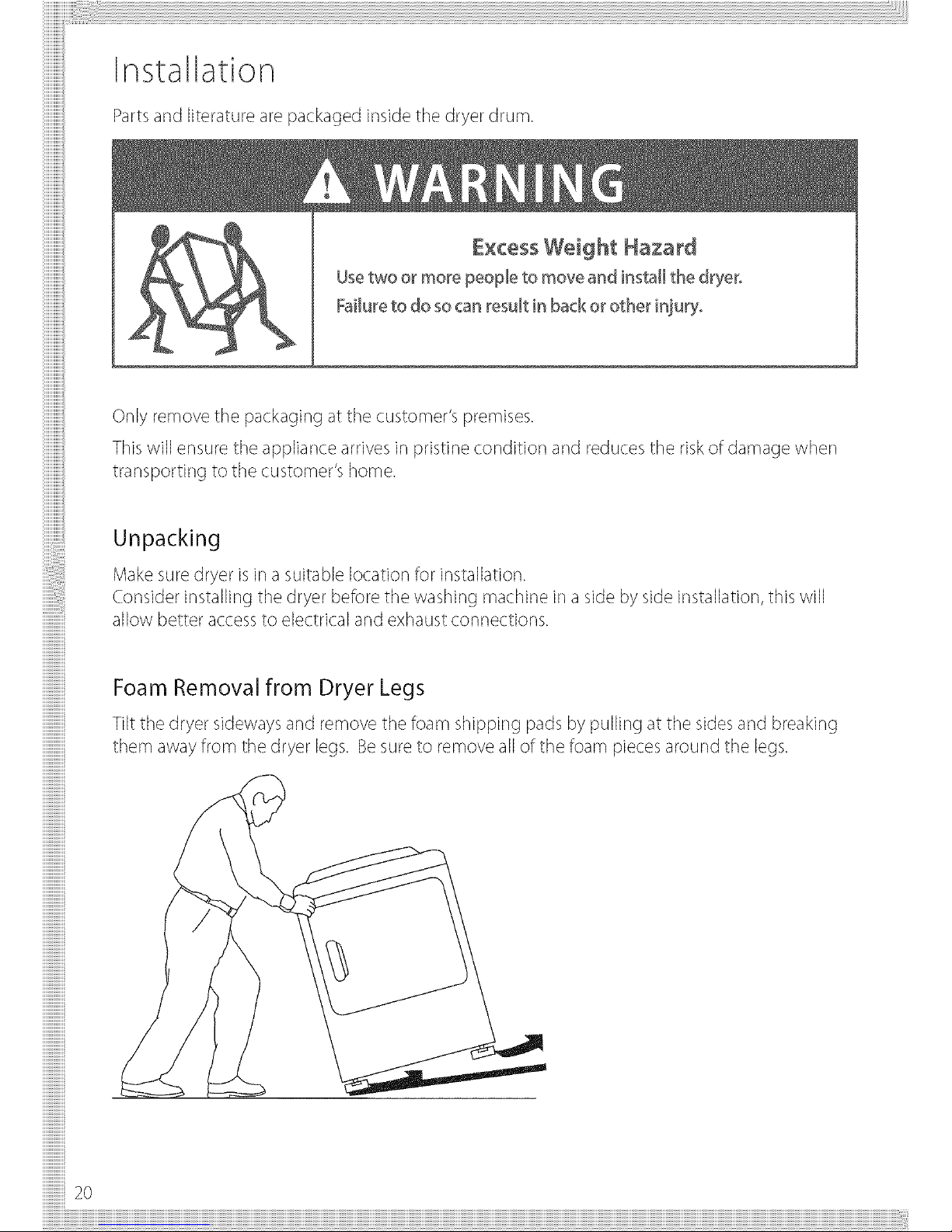
Installation
Partsand literature are packaged inside the dryer drum.
Usetwo or more people to move and install the drye_o
Failureto do socan result [n back or other injury°
Only remove the packaging at the customer's premises.
Thiswill ensure the appliance arrives in pristine condition and reduces the riskof damage when
transporting to the customer's home.
iiiilililililililililililililil
!i!i!i!i!i!i!i!i!i!i!i!i!i!i!i!
iiiilililililililililililililil
iiiiiiiiiiiiiiiiiiiiiiiiiiiiiii
iiiiiiiiiiiiiiiiiiiiiiiiiiiiiii
iiiiiiiiiiiiiiiiiiiiiiiiiiiiiii
iiiiiiiiiiiiiiiiiiiiiiiiiiiiiii
iiiiiiiiiiiiiiiiiiiiiiiiiiiiiii
iiiiiiiiiiiiiiiiiiiiiiiiiiiiiii
iiiiiiiiiiiiiiiiiiiiiiiiiiiiiii
iiiiiiiiiiiiiiiiiiiiiiiiiiiiiii
!!!!!!!!!!!!!!!_
!i!i!i!i!i!i!i!i!i!i!i!i!i!i!i!2o
Unpacking
Make sure dryer isin a suitable location for installation.
Consider installing the dryer before the washing machine in aside by side installation, this will
allow better accessto electrical and exhaust connections.
Foam Removal from Dryer Legs
Tilt the dryer sideways and remove the foam shipping pads by pulling at the sidesand breaking
them away from the dryer legs. Besureto remove all of the foam pieces around the legs.
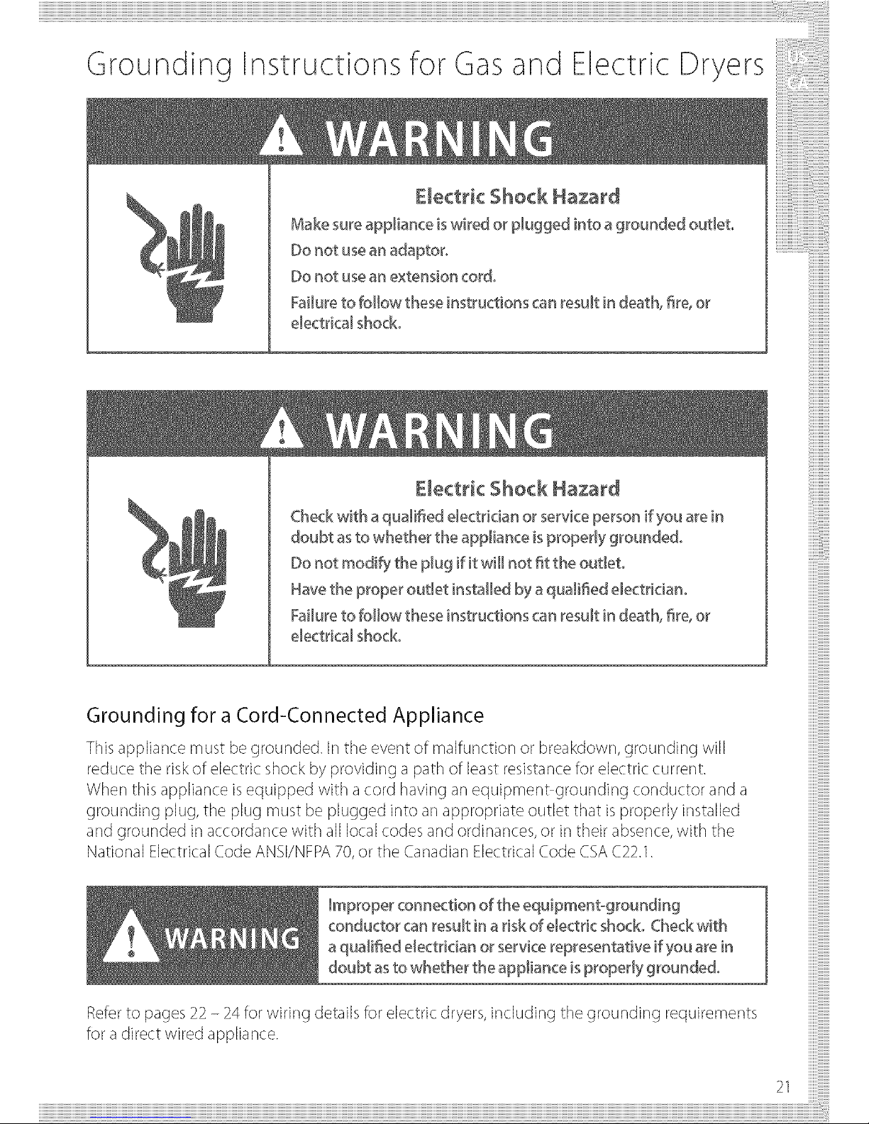
Grounding Instructions for Gasand Electric Dryers
£lect_i¢ Shock Hazard
Make sure appliance iswired or plugged into a grounded out[e'to
Do not usean adaptor°
Do not usean extension cord°
Failureto follow these instructions can result in death, fire,or
electrical shock.
El÷€tHe Shock Hazard
Check with a qualifed electrician or service person if you arein
doubt asto whether the appliance isproperly grounded°
Do not modify the plug if it will not fit the outlet.
Havethe proper outlet installed by aquaJifed e[ectriciano
Failureto follow these instructions can result in death, fire,or
electrical shock°
Grounding for a Cord-Connected Appliance
This appliance must be grounded. Jr]the event of malfunction or breakdown, grounding will
reduce the riskof electric shock by providing a path of least resistancefor electric current.
When this appliance isequipped with a cord having an equipment grounding conductor and a
grounding plug, the plug must be plugged into an appropriate outlet that isproperly installed
and grounded in accordance with all local codes and ordinances, or in their absence,with the
National Electrical Code ANSI/NFPA70,or the Canadian Electrical Code CSAC22.1.
Improper connection of the equipmentogroundin9
conducto_ can result in a risk of electric shock. Check with
aqualified electrician or service representative if you are [n
doubt asto whether the appliance [sproperty grounded°
Referto pages 22 - 24 for wiring details for electric dryers, including the grounding requirements
for a direct wired appliance.
21
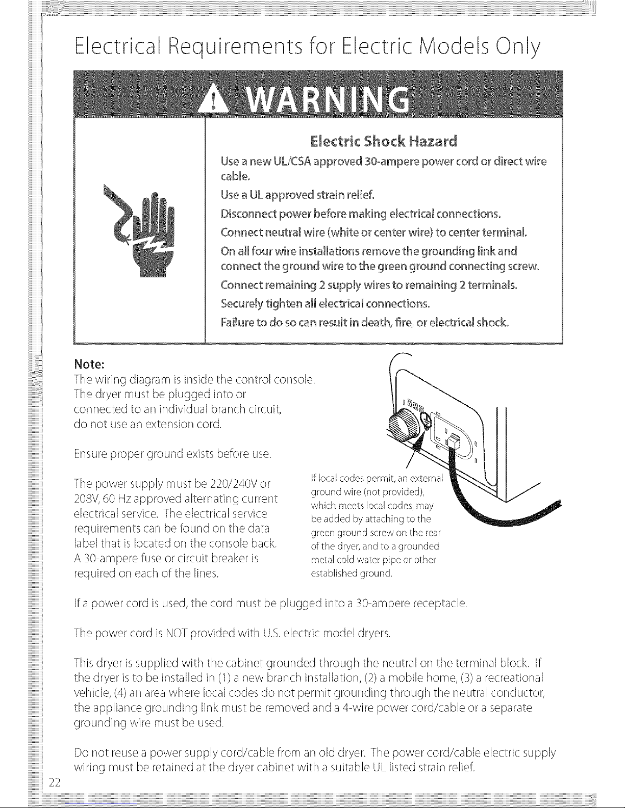
Electrical Requirements for Electric Models Only
Usea new UL/_SAapproved 30._ampereDower cord or direct wire
cab[co
Usea ULapproved strain re[[efo
Disconnect Dower before making e[ectrk:a[connect[onso
Connect neutral wire (white or center wire) to center terminal
On a[[four wire installations remove 'thegrounding [ink and
connect the ground wire to the green ground connecting screw°
Connect remaining 2supply wires to remaining 2terminalso
Securely tighten a[[ electrical connections°
Failureto do socan result in death, fire, or electrical shock°
!i!i!i!i!i!i!i!i!i!i!i!i!i!i!i!
iiiiiiiiiiiiiiiiiiiiiiiiiiiiiii
iiiilililililililililililililil
iiiiiiiiiiiiiiiiiiiiiiiiiiiiiii
iiiiiiiiiiiiiiiiiiiiiiiiiiiiiii
!i!i!i!i!i!i!i!i!i!i!i!i!i!i!i!
!i!i!i!i!i!i!i!i!i!i!i!i!i!i!i!
iiiiiiiiiiiiiiiiiiiiiiiiiiiiiii
iiiilililililililililililililil
iiiilililililililililililililil
iiiilililililililililililililil
iiiiiiiiiiiiiiiiiiiiiiiiiiiiiii
iiiilililililililililililililil
iiiiiiiiiiiiiiiiiiiiiiiiiiiiiii
iiiilililililililililililililil
iiiiiiiiiiiiiiii
!i!i!i!i!i!i!i!i!i!i!i!i!i!i!i!
!i!i!i!i!i!i!i!i!i!i!i!i!i!i!i!
!i!i!i!i!i!i!i!i!i!i!i!i!i!i!i!
iiiiiiiiiiiiiiiiiiiiiiiiiiiiiii
iiiilililililililililililililil
iiiiiiiiiiiiiiii
!i!i!i!i!i!i!i!i!i!i!i!i!i!i!i!
iiiilililililililililililililil
!i!i!i!i!i!i!i!i!i!i!i!i!i!i!i!22
Note:
Thewiring diagram isinside the control console.
The dryer must be plugged into or
connected to an individual branch circuit,
do not usean extension cord.
Ensureproper ground exists before use.
The power supply must be 220/240V or
208V,60 Hzapproved alternating current
electrical service. The electrical service
requirements carl be found on the data
label that islocated or]the console back.
A 30 ampere fuse or circuit breaker is
required or] each of the lines.
if local codes permit, an external
ground wire (not provided),
which meets local codes, may
be added by attaching to the
green ground screw on the rear
of the dryer, and to a grounded
metal cold water pipe or other
established ground.
Ifa power cord is used,the cord must be plugged into a 30 ampere receptacle.
The power cord is NOTprovided with U.S.electric model dryers.
Thisdryer issupplied with the cabinet grounded through the neutral or] the terminal block. If
the dryer isto be installed in(1) a new branch installation, (2)a mobile home, (3)a recreational
vehicle, (4)an area where local codes do not permit grounding through the neutral conductor,
the appliance grounding link must be removed and a4 wire power cord/cable or a separate
grounding wire must be used.
Do not reuse a power supply cord/cable from an old dryer. The power cord/cable electric supply
wiring must be retained at the dryer cabinet with a suitable UL listed strain relief.
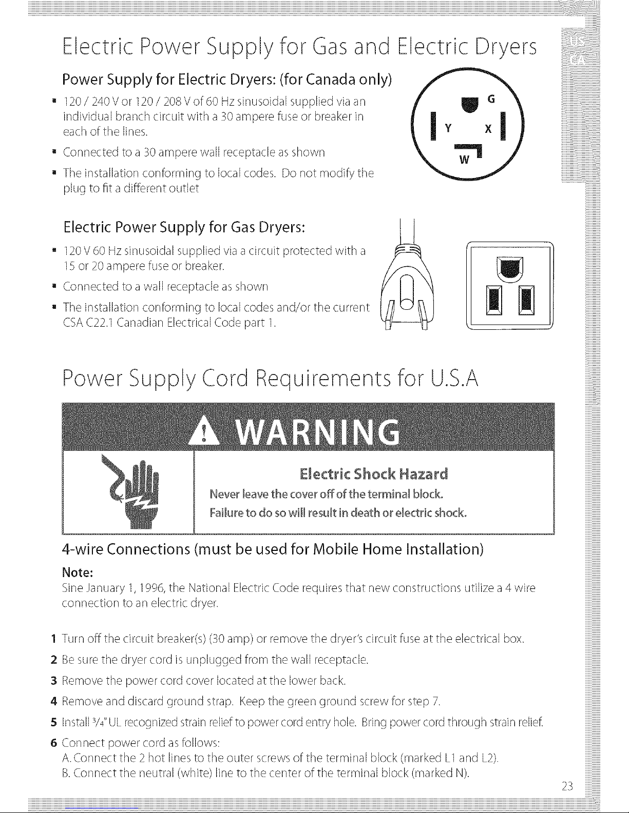
Electric Power Supply for Gasand Electric Dryers
Power Supply for Electric Dryers: (for Canada only)
120/ 240Vor 120/ 208 V of 60 Hzsinusoidal supplied via an
individual branch circuit with a30 ampere fuse or breaker in
eachof the lines.
a Connected to a 30 ampere wall receptacle as shown
a The installation conforming to local codes. Do not modify the
plug to fit a different outlet
iiiiiiiiiiiiii
iiiiiiiiiiiiii
iiiiiiiiiiiiiiiii
iiiiiiiiiiiiiiiii
iiiiiiiiiiiiiiiiiiii
Electric Power Supply for Gas Dryers:
120V60 Hz sinusoidal supplied via a circuit protected with a
15or 20ampere fuse or breaker.
Connected to a wall receptacle as shown
The installation conforming to local codes and/or the current
CSAC22.1Canadian Electrical Code part 1.
ii
Power Supply Cord Requirements for U.S.A
Emoct_icShockHozo_d
Neve_leave the cove_off of the terminal block°
Failureto do sowill result in death o_dect_'k: shock°
4-wire Connections must be used for Mobile Home Installation)
Note:
SineJanuary 1,1996,the National Electric Code requires that new constructions utilize a 4 ,,ire
connection to an electric dryer.
1 Turn off the circuit breaker(s)(30 amp)or remove the dryer's circuit fuse at the electrical box.
2 Besure the dryer cord is unplugged from the wall receptacle.
:3Remove the power cord coverlocatedatthe lower back.
4 Remove and discard ground strap. Keep the green ground screw for step 7.
5 Installs/4"ULrecognizedstrainreliefto power cord entry hole. Bringpower cord through strain relief.
6Connectpowercordasfollows:
A.Connect the 2 hot linesto the outer screwsof the terminal block (marked L1and L2).
B.Connect the neutral (white) line to the center of the terminal block (marked N).
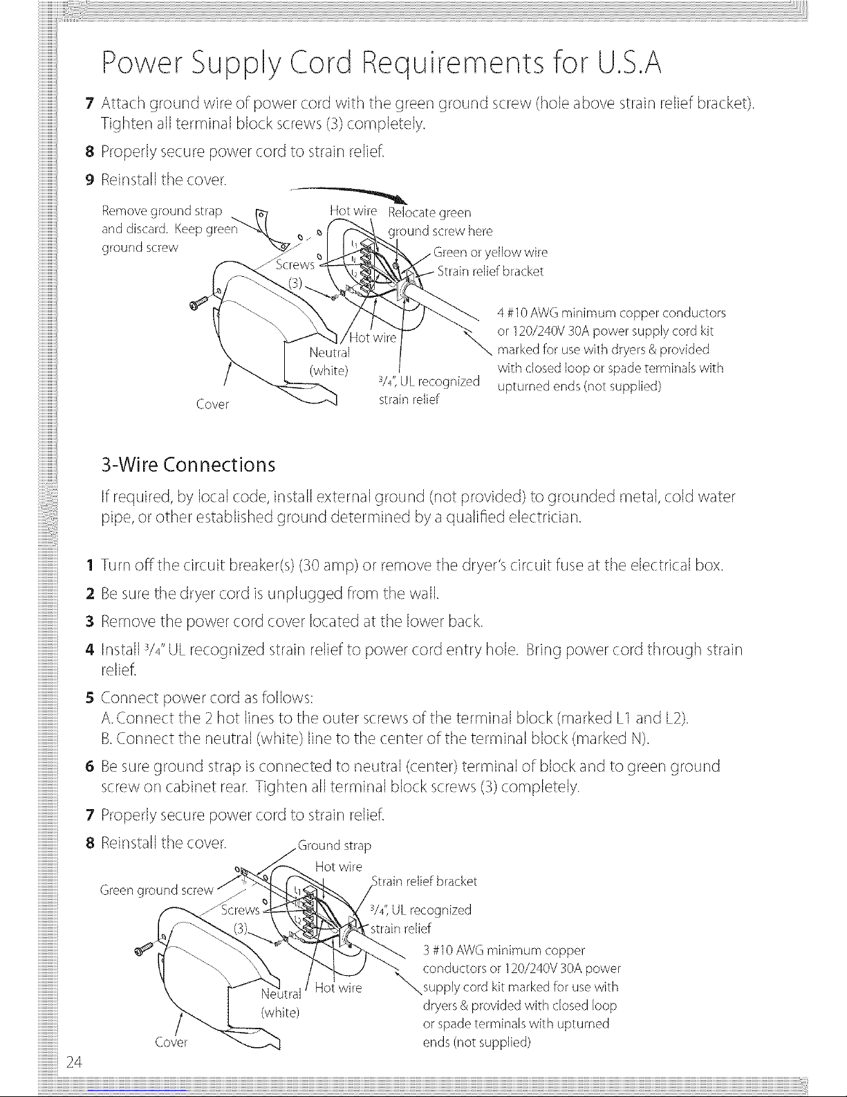
Power Supply Cord Requirements for U.S.A
7 Attach ground wire of power cord with the green ground screw (hole above strain relief bracket).
Tighter] all terminal block screws (3)completely.
8 Properly secure power cord to strain reliefl
9 Reinstallthe cover.
Removeground strap
anddiscard. Kee
ground screw
Hot wire Relocate green
ound screw here
bracket
3/4",UL recognized
Cover strain relief
4 #10 AWG minimum copper conductors
or 120/240V 30A power supply cord kit
marked for use with dryers & provided
with closed loop or spade terminals with
upturned ends (not supplied)
3-Wire Connections
iiiiiiiiiiiiiiiiiiiiiiiiiiiiiii
iiiiiiiiiiiiiiiiiiiiiiiiiiiiiii
iiiiiiiiiiiiiiiiiiiiiiiiiiiiiii
iiiiiiiiiiiiiiiiiiiiiiiiiiiiiii
iiiilililililililililililililil
B_B_B_B
iiiiiiiiiiiiiiiiiiiiiiiiiiiiiii
iiiiiiiiiiiiiiiiiiiiiiiiiiiiiii
iiiilililililililililililililil
B_B_B_B
iiiilililililililililililililil
iiiilililililililililililililil
iiiiiiiiiiiiiiiiiiiiiiiiiiiiiii
iiiilililililililililililililil
iiiiiiiiiiiiiiiiiiiiiiiiiiiiiii
iiiiiiiiiiiiiiiiiiiiiiiiiiiiiii
iiiiiiiiiiiiiiiiiiiiiiiiiiiiiii
iiiiiiiiiiiiiiiiiiiiiiiiiiiiiii
iiiiiiiiiiiiiiiiiiiiiiiiiiiiiii
iiiiiiiiiiiiiiiiiiiiiiiiiiiiiii
!i!i!i!i!i!i!i!i!i!i!i!i!i!i!i!24
Ifrequired, by local code, install external ground (not provided) to grounded metal, cold water
pipe,or other established ground determined by a qualified electrician.
1 Turn off the circuit breaker(s) (30 amp) or remove the dryer's circuit fuse at the electrical box.
2 Besure the dryer cord isunplugged from the wall.
3 Removethe power cord cover located at the lower back.
4 Jr]stallV4"ULrecognized strain relief to power cord entry hole. Bring power cord through strain
relief.
5 Cor]nect power cord asfollows:
A.Connect the 2 hot linesto the outer screws of the terminal block (marked L1and L2).
B.Connect the neutral (white) line to the center of the terminal block (marked N).
6 Besure ground strap isconnected to neutral (center) terminal of block and to green ground
screw or] cabinet rear.Tighter] all terminal block screws (3)completely.
7 Properly secure power cord to strain relief.
8 Reinstallthe cover, strap
Hot wire
Green ground
Cover
(white)
ot wire
W', ULrecognized
"strainrelief
3#10AWGminimum copper
conductors or 120/240V30A power
supplycord kit markedfor usewith
dryers&provided with closed loop
or spadeterminals with upturned
ends(not supplied)
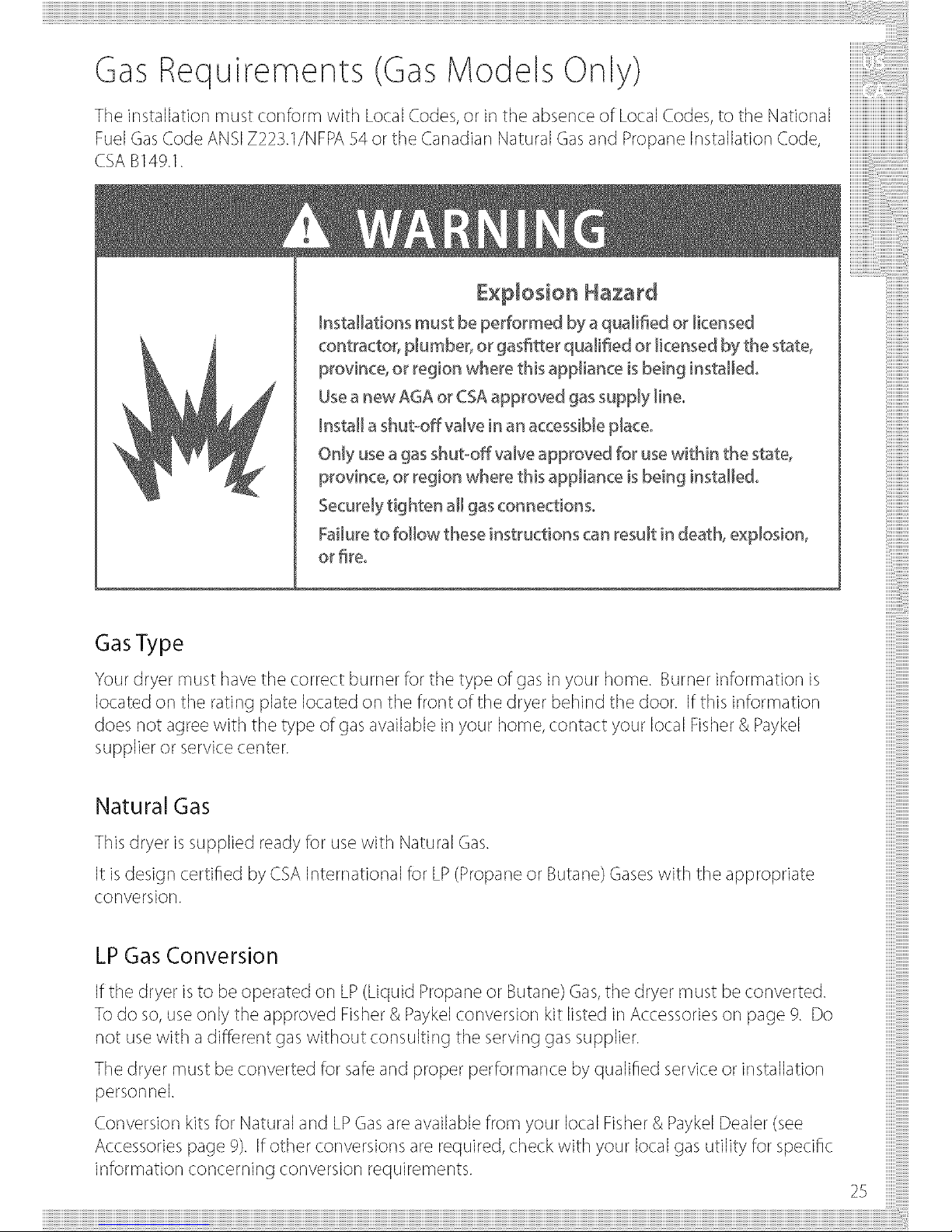
Theinstallationmustco ]formwithLocalCodes,orit]theabsenceofLocalCodes,totheNatio ]aliiiiiiiii!!!!!!iii
FuelGasCodeANSiZ22S._/NFPAS4ortheCanadianNaturalC_asandPropaneInstaUat_onCode,
CSAB149.1.
£×D[osion Hazard
installations must be performed by aqua[i_ed or licensed
contractor, plumber, or gas_tter qualified or licensed by the stat÷_
province, or region where this appliance isbeing installed°
Useanew AGA or CSAapproved gassupply [ineo
Insta[[a shuboff vaJvein an accessibJep[aceo
OnJyusea gas shut-off vaJveapproved for usewithin the stat÷_
province, or region where this appJianceisbeing instaJJedo
Securely tighten a[[ gasconnections°
Failureto follow these instructions can result in death, e×pJosion_
or _reo
GasType
Your dryer must have the correct burner for the type of gas in your home. Burner information is
located or] the rating plate located or] the front of the dryer behind the door. Ifthis information
does not agree with the type of gasavailable in your home, contact your local Fisher& Payke[
supplier or service center.
Natural Gas
This dryer issupplied ready for usewith Natural Gas.
It isdesign certified by CSA International for LP(Propane or Butane) Gaseswith the appropriate
conversion.
LP Gas Conversion
Ifthe dryer isto be operated or] LP(Liquid Propane or Butane) Gas,the dryer must be converted.
Todo so,use only the approved Fisher& Payke[conversion kit listed in Accessories or] page 9. Do
not usewith a different gas without consulting the serving gas supplier.
The dryer must be converted for safeand proper performance by qualified service or installation
personne[.
Conversion kits for Natural and LPGasareavailable from your local Fisher& PaykelDealer (see
Accessories page 9). If other conversions are required, check with your local gas utility for specific
information concerning conversion requirements.
25
Connecting Gasto Your Dryer (GasModels Only)
Usecompound or thread tape appropriate to the gas type that isto be used (Natural or LPGas),
or] the male threads of all non flared connections.
Never usean open flame to test for gas leaks.
This dryer will operate satisfactorily up to altitudes of 2000m (6SOOft)above sealevel at the
BTUrating indicated on the model/serial plate. Burner input adjustments may be required if
operating above this elevation.
The dryer must be isolated from the gas supply piping system by closing the supply shut off
valve during any pressuretesting of the gas supply piping system.
Gas Ignition
This dryer hasan automatic ignition system to ignite the burner. There is no pilot flame burning
in this dryer.
!i!i!i!i!i!i!i!i!i!i!i!i!i!i!i!
iiiiiiiiiiiiiiiiiiiiiiiiiiiiiii
iiiiiiiiiiiiiiiiiiiiiiiiiiiiiii
iiiilililililililililililililil
iiiilililililililililililililil
iiiiiiiiiiiiiiiiiiiiiiiiiiiiiii
iiiiiiiiiiiiiiiiiiiiiiiiiiiiiii
iiiiiiiiiiiiiiiiiiiiiiiiiiiiiii
iiiiiiiiiiiiiii
iiiiiiiiiiiiiii
iiiiiiiiiiiiiii
iiiiiiiiiiiiiii
iiiiiiiiiiiiiii
iiiiiiiiiiiiiii
!i!i!i!i!i!i!i!i!i!i!i!i!i!i!i!26
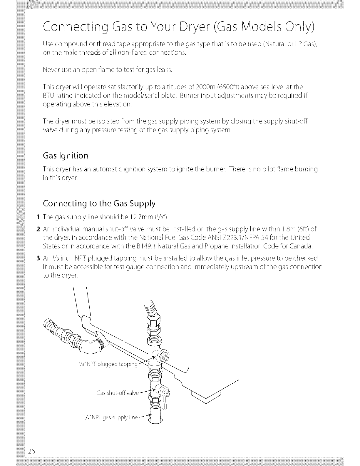
Connecting to the Gas Supply
1 The gas supply line should be 12.7mm (1/2'%
2 An individual manual shut off valve must be installed on the gas supply line within 1.8m(6ft) of
the dryer, in accordance with the National FuelGasCode ANSIZ223.1/NFPA 54 for the United
Statesor in accordance with the B149.1Natural Gasand Propane Installation Code for Canada.
3 An % inch NPTplugged tapping must be installed to allow the gas inlet pressure to be checked.
it must be accessible for test gauge connection and immediately upstream of the gasconnection
to the dryer.
%" NPT plugged tapping
V2"NPT
Connecting Gasto Your Dryer (GasModels Only)
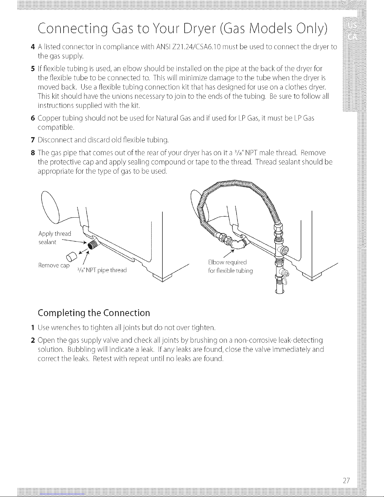
4 A listed connector in compliance with ANSIZ21.24/CSA6.10 must be used to connect the dryer to
the gas supply.
5 If flexible tubing is used,an elbow should be installed on the pipe at the back of the dryer for
the flexible tube to be connected to. This will minimize damage to the tube when the dryer is
moved back. Useaflexible tubing connection kit that hasdesigned for useor] a clothes dryer.
This kit should have the unions necessary to join to the ends of the tubing. Besure to follow all
instructions supplied with the kit.
6 Copper tubing should not be used for Natural Gasand if used for LPGas,it must be LPGas
compatible.
7 Disconnect and discard old flexible tubing.
8 The gas pipe that comes out of the rear of your dryer hasor] it a sA"NPTmale thread. Remove
the protective cap and apply sealing compound or tape to the thread. Thread sealant should be
appropriate for the type of gasto be used.
' %" NPT pipe thread %
S
Elbowrequired
forflexibletubing
ijjjjjjjjjjjjjjjJ_iii_
Completing the Connection
1 Use wrenches to tighter] all joints but do not over tighter].
2 Open the gas supply valve and check alljoints by brushing or] a non corrosive lea_detecting
solution. Bubbling will indicate a leak. If any leaks arefound, close the valve immediately and
correct the leaks. Retest with repeat until no leaksarefound.
27
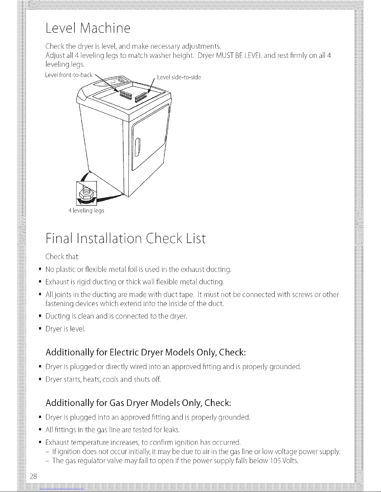
Final Installation Check List
Check that:
• No plastic or flexible metal foil isused in the exhaust ducting.
• Exhaustis rigid ducting or thick wall flexible metal ducting.
• All joints in the ducting are made with duct tape. It must not be connected with screws or other
fastening devices which extend into the inside of the duct.
• Ducting is clear] and isconnected to the dryer.
• Dryer is level.
Additionally for Electric Dryer Models Only, Check:
• Dryer is plugged or directly wired into an approved fitting and is properly grounded.
• Dryer starts,heats,cools and shuts off
Additionally for Gas Dryer Models Only, Check:
• Dryer is plugged into an approved fitting and is properly grounded.
• All fittings in the gas line are tested for leaks.
• Exhausttemperature increases,to confirm ignition hasoccurred.
- If ignition does not occur initially, it may be due to air in the gas line or low voltage power supply.
- The gas regulator valve may fail to open if the power supply falls below 105Volts.

Features
Extra Care
• Use this option to minimize the wrinkles in clothes. This option provides
approximately 15minutes of no heat tumbling after the clothes aredry.
This option car] only be used with the Automatic cycles.
Hint: If the Signal option is selected, the Signal will sound at the end of the drying
time and will sound severaltimes during the ExtraCarecycle. This will remind you
that the cycle iscomplete.
o
Signal
This signal will sound just before the end of the cycle to remind you to remove the
clothes.
Ifyou selected the ExtraCareoption a signal will sound a the end of the drying
time and will sound severaltimes during the ExtraCarecycle.
This will remind you that the dry cycle iscomplete and you should remove your
clothes.
Note:
• Removegarments promptly at the sound of the signak Placeclothes or] hangers
so wrinkles won't set in.
• Usethe Signal especially when drying fabrics like polyester knits and permanent
press.These fabrics should be removed promptly so wrinkles won't set in.
o
Reset Options
Selecting ResetOptions canceB all options that have beer] selected.
Drum Lamp
A handy light inside the dryer to help make unloading easier.
Drying Rack (Optional or] some models)
A handy drying rack may be used for drying articles such as stuffed
toys, pillows or washable sweaters.
Hook the rack over the lint filter so the rackextends into the dryer
drum.
Note:
The drying rack must be used with the Timed cycle. Do not use this
drying rack when there are other clothes in the dryer.
\\
29
Operating Instructions Control
Automatic Drying Cycles
(Cycleautomatically sensesdryness)
Panel
There aretwo automatic dryness levels:More Dry (+) and Less Dry (-).
Thesetwo settings dry your clothes to different degrees depending or] the level of dryness you
would like.
Automatic Permanent Press - Forsynthetic blends. Select More Dry (+) for heavier fabrics,
Less Dry (-) for light fabrics.
Automatic Permanent Press - Forlingerie and special care fabrics. Select More Dry (+) for
larger fabrics, Less Dry (-) for smaller fabrics.
Automatic Cottons - Forcottons and most linens. For most loads select the preferred Regular
Setting marked with an _. Settowards More Dry (+) for heavier fabrics, Less Dry (-) for lighter
fabrics.
_ii \ F_bdc Cam
Ha Hem'm_ Mad Lew
\ Heat Hea_ Heat Heet
<:) , <:
RuH C#H## Pem_#e#¢ KM_
_eg_ r Press Dd_eaCes
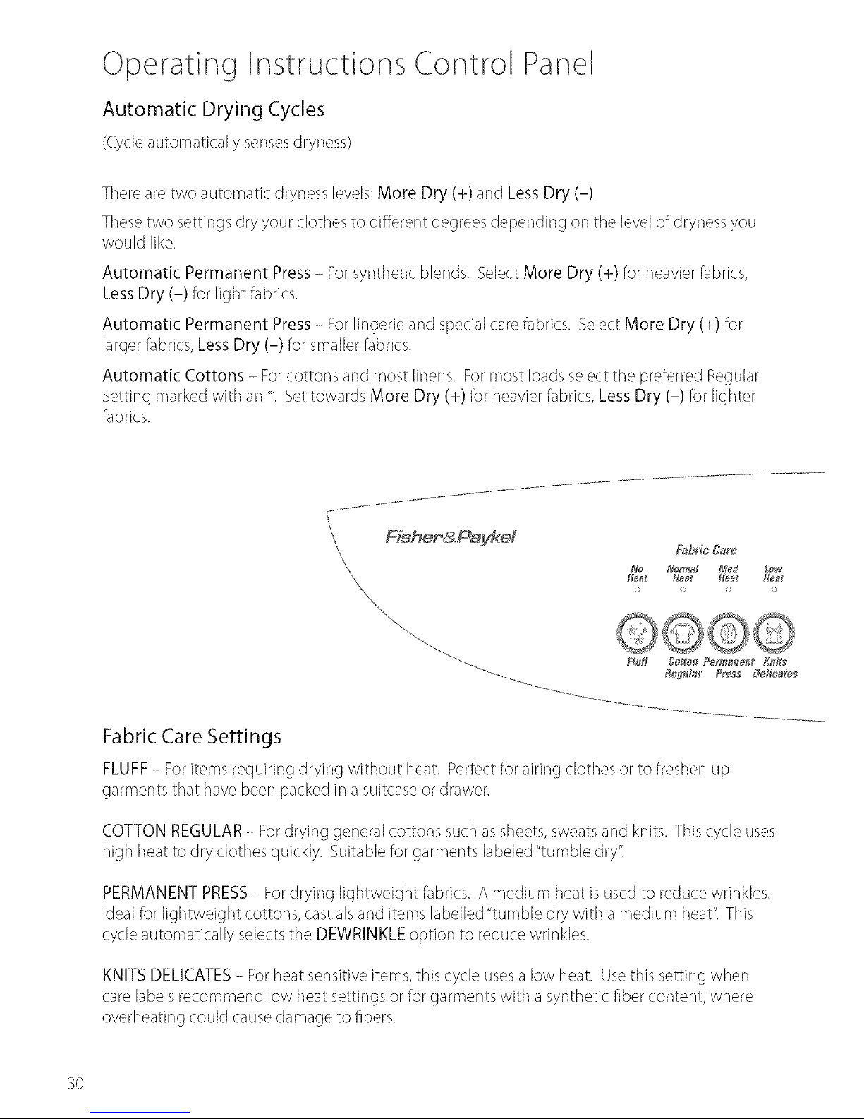
Fabric Care Settings
FLUFF- Foritems requiring drying without heat. Perfect for airing clothes or to fresher] up
garments that have beer] packed in asuitcase or drawer.
COTTON REGULAR- Fordrying general cottons such as sheets, sweatsand knits. This cycle uses
high heat to dry clothes quickly. Suitable for garments labeled "tumble dry't
PERMANENT PRESS- Fordrying lightweight fabrics. A medium heat is used to reduce wrinkles.
Ideal for lightweight cottons, casualsand items labelled "tumble dry with a medium heat't This
cycle automatically selectsthe DEWRINKLE option to reduce wrinkles.
KNITS DELICATES- For heat sensitive items, this cycle usesa low heat. Usethis setting when
care labels recommend low heat settings or for garments with a synthetic fiber content, where
overheating could causedamage to fibers.
3O
 Loading...