

Fisher & Paykel DishDrawer DD24D Series, DishDrawer DD24S Series, DishDrawer DD60D Series, DishDrawer DD60S Series Service Manual

Service Manual
DishDrawer™
Models:
DD24D
DD24S
DD60D
DD60S
599735A

599735A
2

599735A - APRIL 2009
PRODUCTS
Brands Fisher & Paykel
DCS
Standard Product Codes
Double Models Description – Markets
DD24DCB6 Double, Prefinished Black 88531 - US
DD24DCW6 Double, Prefinished White 88526 - US
DD24DCX6 Double, Prefinished Brushed Stainless 88527 - US
DD24DDFX6 Double, Designer, Brushed Stainless 88532 - US
DD24DI6 Double, Integrated 88529 - US
DD60DCB6 Double, Prefinished Black 80576 - NZ/AU
DD60DCHB6 Double, Prefinished Black, Water Softener 89227 - GB
DD60DCHW6 Double, Prefinished White, Water Softener 89240 - DK
DD60DCHX6 Double, Brushed Stainless, water softener 89225 - GB
89241 - DK
89234 - EU
DD60DCM6 Double, Iridium Stainless 80591 - NZ/AU
DD60DCW6 Double, Prefinished White 80588 - NZ/AU
DD60DCX6 Double, Brushed Stainless 80589 - NZ/AU
DD60DDFHX6 Double, Designer, Brushed Stainless, Water Softener 89228 - GB
89236 - EU
89243 - DK
DD60DDFM6 Double, Designer, Iridium 80592 - NZ/AU
DD60DDFX6 Double, Designer, Brushed Stainless 80593 - NZ/AU
DD60DI6 Double, Integrated 80590 - NZ/AU
DD60DIH6 Double, Integrated, Water Softener 89226 - GB
89235 - EU
89242 - DK
3

599735A
Standard Product Codes
Single Models Description – Markets
DD24SCW6 Single, prefinished, white 88519 - US
DD24SCX6 Single, prefinished, Brushed Stainless 88520 - US
DD24SCB6 Single, prefinished, Black 88524 - US
DD24SI6 Single Integrated 88522 - US
DD24SDFX6 Single, designer, Brushed Stainless 88525 - US
DD60SCHW6 Single, Prefinished White, Water Softener 89229 - GB
89244 - DK
DD60SCHX6 Single, Brushed Stainless, Water Softener 89230 - GB
89237 - EU
89245 -DK
DD60SIH6 Single, Integrated, Water Softener 89231 - GB
89238 - EU
89246 - DK
DD60SCHB6 Single, Prefinished Black, Water Softener 89232 - GB
DD60SDFHX6 Single, Designer, Brushed Stainless, Water Softener 89233 - GB
89239 - EU
89247 - DK
DD60SCHLI6 Single, Integrated, Long Door 89248 - DK
DD60SDFM6 Single, Designer, Iridium Stainless 80601 - NZ/AU
DD60SDFX6 Single Designer, Brushed Stainless 80602 - NZ/AU
DD60SI6 Single, Integrated 80596 - NZ/AU
DD60SCB6 Single, Prefinished Black 80583 - NZ/AU
DD60SLX6 Single, Brushed Stainless 80597 - NZ/AU
DD60SCM6 Single, Iridium Stainless 80600 - NZ/AU
DD60SLFX6 Single, Long Door 80603 - NZ/AU
DD60SCHW6 Single, Water Softener, Prefinished White 89173 -TW
DD60SCHX6 Single, Water Softener, Brushed Stainless 89174 - TW
DD60SIH6 Single , Water Softener, Integrated 89175 - TW
Tall Tub Product Codes
Double Models Description – Markets
DD24DDFTX6 Double Designer, Brushed Stainless Tall Tub 88502 - US
DD24DTI6 Double Integrated, Tall Tub 88504 - US
DD24DCCTX6 Double Curved Door, Curved Handle, Tall Tub 88518 - US
DD24DCTX6 Double, Brushed Stainless, Tall Tub 88511 - US
DD24DCHTX6 Double, Brushed Stainless, Water Softener 88528 - US
DD24DHTI6 Double, Integrated, Water Softener 88530 - US
DD24DCTW6 Double, Tall Tub, Prefinished White 88514 - US
DD24DCTB6 Double, Tall Tub, Prefinished Black 88509 - US
DD24DUT Double, Tall Tub 88542 - DCS US
4

599735A
Tall Tub Product Codes
Single Models Description – Markets
DD24SDFTX6 Single, Designer, Tall Tub, Brushed Stainless 88503 - US
DD24STI6 Single Integrated, Tall Tub 88505 - US
DD24SCTX6 Single, Brushed Stainless Steel 88512 - US
DD24SCCTX6 Single Curved Door, Curved Handle, Tall Tub 88513 - US
DD24SCTW6 Single, Tall Tub, Prefinished White 88515 - US
DD24SCTB6 Single, Tall Tub, Black 88510 - US
DD24SCHTX6 Single, Brushed Stainless, Water Softener, Tall Tub 88521 - US
DD24SHTI6 Single, Integrated, Water Softener, Tall Tub 88523 - US
DD60SHTI6 Single, Integrated, Tall Tub, Water Softener 89271 - GB
89273 - EU
89275 - DK
DD60SDFHTX6 Single, Designer, Brushed Stainless, Tall Tub, Water
Softener.
89272 - EU
89274 – DK
89270 - GB
DD60SDFTX6 Single, Designer, Brushed Stainless, Tall Tub 80644 - NZ/AU
DD60SDFTM6 Single, Designer, Iridium Stainless, Tall Tub 80645 - NZ/AU
DD60STI6 Single Integrated, Tall Tub 80646 - NZ/AU
DD24SUT Single, Tall Tub 88541 - DCS US
The specifications and servicing procedures outlined in this manual are subject to change without
notice.
The latest version is indicated by the reprint date, and replaces any earlier versions.
Fisher & Paykel Appliances Ltd
78 Springs Road,
East Tamaki,
PO Box 58-732, Greenmount,
Auckland,
New Zealand
Phone: 09 273 0600
Fax: 09 273 0656
Email: customer.care@fp.co.nz
Fisher & Paykel Appliances
Unit D2
North Dublin Corporate Park
Swords
Co Dublin
Ireland
Telephone: 1800 625 174
Facsimile: 1800 635 012
E-mail: customer.care@fisherpaykel.ie
Fisher & Paykel Customer Services Pty Ltd
PO Box 798, Cleveland, QLD 4163
A.C.N. 003 3335 171
19 Enterprise Street
Cleveland, QLD 4163
Australia
Telephone: (07) 3826 9100
Facsimile: (07) 3826 9164
E-mail: customer.care@fp.com.au
Fisher & Paykel Appliances Inc
5800 Skylab Rd,
Huntington Beach
California, CA92647
USA
Telephone: 888 936 7872
E-mail: customer.care@fishpaykel.com
5
Fisher & Paykel Appliances Ltd U.K
Maidstone Road
Kingston
Milton Keynes
Buckinghamshire
MK10 0BD
England
Telephone: 0845 066 2200
Facsimile: 0845 331 2360
E-mail:
customer.care@fisherpaykel.co.uk

599735A
CONTENTS
1 SERVICE REQUIREMENTS......................................................................................................9
1.1 Health & Safety....................................................................................................................9
1.1.1 Electrical Safety .............................................................................................................9
1.1.2 Electrostatic Discharge ..................................................................................................9
1.1.3 Good Working Practices ................................................................................................9
1.1.4 Isolate Water Supply......................................................................................................9
1.1.5 Water Leak Check .........................................................................................................9
1.1.6 Insulation Test................................................................................................................9
1.1.7 Solvent and Excessive Heat Damage............................................................................ 9
1.1.8 Sheet Metal Edges......................................................................................................... 9
1.1.9 Diagnostics ..................................................................................................................10
1.2 Specialised Tools ..............................................................................................................10
1.2.1 Static Strap ..................................................................................................................10
1.2.2 Fisher & Paykel Smart Tool .........................................................................................10
2 DIMENSIONS & SPECIFICATIONS........................................................................................11
2.1 Dimensions ........................................................................................................................11
2.2 Specifications ....................................................................................................................11
2.2.1 Electrical ......................................................................................................................11
2.2.2 Components................................................................................................................. 11
2.2.3 Performance ................................................................................................................13
2.2.4 Wash Profiles...............................................................................................................13
3 TECHNICAL OVERVIEW ........................................................................................................15
1.1 Chassis ..............................................................................................................................15
1.2 Drawer Fronts ....................................................................................................................15
3.1 Electronics .........................................................................................................................15
3.1.1 Tub Home Sensor........................................................................................................16
3.1.2 Touch Switches............................................................................................................ 16
3.2 Motor..................................................................................................................................16
3.2.1 Rotor ............................................................................................................................16
3.2.2 Spray Arm .................................................................................................................... 16
3.3 Wiring Cover ......................................................................................................................16
3.4 Lid System .........................................................................................................................16
3.4.1 Lid Operation ...............................................................................................................16
3.4.2 During a Power Failure ................................................................................................17
3.5 Tub.....................................................................................................................................17
3.6 Filling .................................................................................................................................17
3.6.1 Water Inlet.................................................................................................................... 17
3.6.2 Dispensing Detergent and Rinse-aid ...........................................................................17
3.6.3 Amount of Water .......................................................................................................... 18
3.6.4 Flood Protection...........................................................................................................18
3.7 Heating ..............................................................................................................................18
3.7.1 The Heating Element ...................................................................................................18
3.7.2 Heating the Water ........................................................................................................ 18
3.7.3 Maintaining the Temperature ....................................................................................... 18
3.7.4 Overheat Protection ..................................................................................................... 18
3.8 Motor and Heater Plate Locknuts ......................................................................................18
3.9 Drain Cycle ........................................................................................................................19
3.10 Filter Plate..........................................................................................................................19
3.10.1 The Filter System........................................................................................................19
3.10.2 Removing and Cleaning the Drain Filter and Filter Plate............................................ 19
3.11 Drying Cycle ......................................................................................................................19
3.12 Water Softener (Where Fitted)...........................................................................................20
3.12.1 Delivering Softened Water..........................................................................................20
3.12.2 Regeneration ..............................................................................................................20
3.12.3 Salt..............................................................................................................................20
6

599735A
4
OPTION ADJUSTMENT MODE..............................................................................................21
4.1 Rinse Aid Setup (rA)..........................................................................................................21
4.2 Water Supply Hardness Setup (hd)...................................................................................21
4.3 Auto Power Option (AP) .................................................................................................... 22
4.4 End of Cycle Beeps (EC) .................................................................................................. 22
4.5 Closed Drawer Option (Ld)................................................................................................22
4.6 Clean/Dirty Dish Symbol (dS)............................................................................................22
4.6.1 Option Adjustment Quick Reference Charts................................................................ 23
5 DIAGNOSTICS ........................................................................................................................25
5.1 DishDrawer™ Diagnostics ................................................................................................ 25
5.1.1 Optical LED Download / Fault Display......................................................................... 25
5.1.2 Clearing Fault Logs...................................................................................................... 25
5.1.3 Hardware Output Diagnostic Test Mode...................................................................... 26
5.1.4 Fast Test Cycle............................................................................................................ 27
5.1.5 Continuous Cycle Test Mode....................................................................................... 28
5.1.6 Cycle Count Retrieval .................................................................................................. 28
5.1.7 Temperature & Voltage Display Mode......................................................................... 28
5.1.8 Show Off / Showroom Wash Mode.............................................................................. 29
5.2 Diagnostics Quick Reference Charts ................................................................................ 30
5.2.1 Fault Display/Download Mode ..................................................................................... 30
5.2.2 Hardware Output Test Mode ....................................................................................... 30
5.2.3 Fast Test Cycle............................................................................................................ 31
5.2.4 Continuous Cycle......................................................................................................... 31
5.2.5 Temperature & Voltage Display Mode......................................................................... 31
6 FAULT CODES AND POOR PERFORMANCE......................................................................32
6.1 Fault Code Description Chart ............................................................................................ 33
6.2 Fault Code Problem Solving Charts .................................................................................. 35
6.3 Poor Dry Performance.......................................................................................................40
6.4 Poor Wash Performance ................................................................................................... 40
7 WIRING DIAGRAMS ...............................................................................................................43
7.1 Power Distribution Concept ............................................................................................... 43
7.2 Wiring Diagram..................................................................................................................44
8 SERVICE PROCEDURES....................................................................................................... 45
8.1 Component Testing ........................................................................................................... 45
8.2 Drawer Front ..................................................................................................................... 46
8.3 Handle and LCD Display ................................................................................................... 47
8.4 Toe Kick Removal .............................................................................................................47
8.5 Lower Tub Cowling............................................................................................................47
8.6 Tub Removal ..................................................................................................................... 48
8.7 Drying Duct - Top Tub Only...............................................................................................48
8.8 Drying Fan and Flap Valve ................................................................................................ 49
8.9 Water Softener (Where Fitted) ..........................................................................................49
8.10 Strainer (Where Fitted)......................................................................................................50
8.11 Detergent Dispenser .........................................................................................................50
8.12 Electronic Controller .......................................................................................................... 51
8.13 Filter Plate .........................................................................................................................51
8.14 Rotor.................................................................................................................................. 51
8.15 Wiring Cover...................................................................................................................... 52
8.16 Tub Disconnection............................................................................................................. 52
8.17 Hall Sensor........................................................................................................................53
8.18 Heater Plate and Motor Assembly..................................................................................... 53
8.19 Lid...................................................................................................................................... 54
8.20 Yoke ..................................................................................................................................55
8.21 Lid Actuator .......................................................................................................................55
8.22 Slide Rail Replacement ..................................................................................................... 56
8.23 Mains Filter Cover and PCB Mains Filter .......................................................................... 56
8.24 Water Inlet Valve ............................................................................................................... 57
7

599735A
Fill Hose, Drain Hose, Wiring Harness Replacement........................................................57
8.25
8.26 Link Support Wire Position ................................................................................................57
8.27 Front Trim Replacement....................................................................................................58
8
599735A
1 SERVICE REQUIREMENTS
1.1 Health & Safety
Note: When servicing the DishDrawer™, Health and Safety issues must be considered at all
times. Specific safety issues are listed below with their appropriate icon. These are illustrated
throughout the service information to remind service people of the Health and Safety issues.
1.1.1 Electrical Safety
Ensure the mains power has been disconnected before servicing the DishDrawer™. If
the mains supply is required to be on to service the DishDrawer™, make sure it is
turned off when removing any electrical component or connection to avoid electrical
shock.
1.1.2 Electrostatic Discharge
An anti-static strap is to be used as electrical static discharge (ESD) protection when
servicing electronic components.
1.1.3 Good Working Practices
Ensure the work area is in a tidy and orderly condition at all times so as not to cause a
hazard while service work is being completed. Always clean and tidy the DishDrawer™
and work area after service is completed.
1.1.4 Isolate Water Supply
Turn off the water connection tap before servicing.
1.1.5 Water Leak Check
Check for water leaks as part of the testing after the service has been completed.
1.1.6 Insulation Test
Megger test to check insulation.
Warning: Short together the phase and neutral pins on the plug so as not to damage
any electronic circuitry.
1.1.7 Solvent and Excessive Heat Damage
Solvents and excessive heat can damage plastic surfaces.
1.1.8 Sheet Metal Edges
When working around cut sheet metal edges use appropriate gloves or protection to
eliminate the chance of receiving a laceration.
9

599735A
1.1.9 Diagnostics
While in diagnostics some safety devices are bypassed.
Ensure you do not run components unattended. They may overheat, flood, burnout or
cause water damage.
1.2 Specialised Tools
For servicing this product specialised tools are required.
1.2.1 Static Strap
To be used as ESD (electrostatic discharge) protection when replacing or handling electronic
components.
1.2.2 Fisher & Paykel Smart Tool
Handheld palm computer supplied in a protective case with F&P diagnostics software and service
information loaded:
Part Number 813141 (includes light pen Part Number 425930).
Smart Tool Software is available to download from service website “Cool Blue World” for laptop /
pocket PC’s. Refer to list of compatible devices on the web site.
www.cbw.fp.co.nz
10
2 DIMENSIONS & SPECIFICATIONS
2.1 Dimensions
599735A
Standard Product Product
Size
(mm)
Height (double) 819.5 -
879.5
Height (single) 409mm 161/8 inch 412mm 161/4 inch
Width 595mm 237/16 inch 600mm 235/8 inch
Depth 570mm 227/16 inch 580mm 227/8 inch
Drawer Open (inc
cabinet)
Tall Tub Product Product
Height (Double) 863.5 –
Height ( Single) 453mm 173/16 inch 456mm 1715/16 inch
Width 595mm 237/16 inch 600mm 235/8 inch
Depth 570mm 227/16 inch 580mm 227/8 inch
Drawer Open (inc
cabinet)
1090mm 42
Size
(mm)
923.5
1090mm 42
Product Size
(inches)
32¼ inch – 345/8
inch
7
/8 inch
Product Size
(Inches)
34inch – 363/8
inch
7
/8 inch
Minimum
Cavity Size
(mm)
822.5 -
882.5mm
Minimum
Cavity Size
(mm)
864 -926.5 34 inch – 361/2
Minimum Cavity
Size (inches)
325/16 inch – 343/4
inch
Minimum Cavity
Size (Inches)
inch
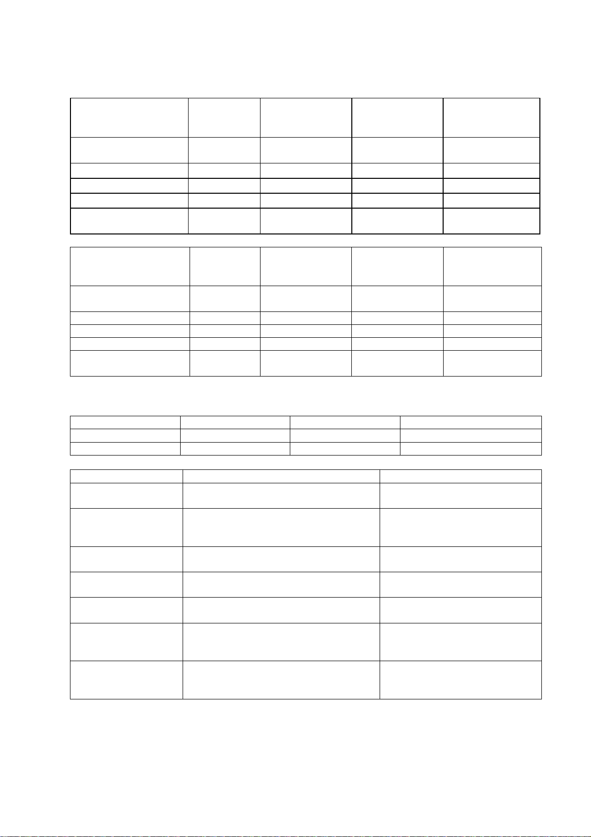
2.2 Specifications
2.2.1 Electrical
Market Voltage Frequency Current Double / Single
NZ/AUS/GB/EU/DK 230/240V AC 50/60 Hz 10 A / 5 A max
USA/TW 110/120V AC 60 Hz 10.6 A / 5.3 A max
2.2.2 Components
Component Specifications Comments
Controller – 2 types 120V
230V
Water Inlet Valve 24V DC
65+/- 10 Ohms per coil
2.5litres/min (0.65 US gal/min)
Dispenser coils
Rinse Aid tank
capacity
PCB Mains Filter – 2
types
Motor
Drain speed
Wash speed
Stator 8.0 +/- 5 Ohms (per winding), 16
24V DC per coil
65+/- 10 Ohms per coil
50mls (approximately 25 washes)
3.05 cubic inches
230V AC
110V AC
80V DC 3 Phase Brushless
4200 RPM
2300 - 2850 RPM
ohms phase to phase from the
controller connector
US, TW, 110V NZ/AU
NZ, AU, GB, EU, DK
All markets
NZ, AU, GB, EU, DK
US, TW, 110V NZ/AU
Pump out rate 5 litres / min.
11

599735A
Component Specifications Comments
Heater Plate 230V
Water Heater Track
Power Supply
230V AC
50 Ohms +/- 4 Ohms
98 Ohms +/- 7 Ohms
NZ, AU, GB, EU, DK
Resistor
Heater Plate 110V
Water Heater Track
Power Supply
Resistor
Temperature Sensor 12000 Ohms @ 20OC (68OF)
120V AC
24 Ohms +/- 3 Ohms
24 Ohms +/- 3 Ohms
8300 Ohms @ 30
3000 Ohms @ 60
O
O
C (86OF)
C (140OF)
US, TW 110V NZ/AU
Located on the heater Plate
Fusible Link 268 – 302OC (514 – 576OF) Located on the heater plate
Water Inlet Hose 1000Kpa / 145 P.S.I.
1561 mm from LHS
1344 mm from RHS
Water pressure 1 MPa (145 psi) max, 0.1 MPa (14.5
psi) min
1 MPa (145 psi) max, 0.03 MPa (4.3
Pressure rating
Length from chassis edge
(viewed from the front)
Water softener models
Non water softener models
psi) min
Drain Hose
Power Cord 1776 mm from LHS (69 Inches)
Drying Fan 24V brushless DC motor 0.27A
2011mm from LHS (79 inches)
1794 mm from RHS (71 inches)
1559 mm from RHS (61 Inches)
Approximately 2 to 3 Meg Ohms
Length from chassis edge
(viewed from the front)
Length from chassis exit
(viewed from the front)
Polarity sensitive
Meter +ve to red wire, -ve to
black wire
Diverter Valve
Softener Assy
Brine Pump Assy 24V DC Coil
24V DC Coil
65 +/- 10 Ohms Coil
65 +/- 10 Ohms Coil
Water Softener 500 grams Salt Capacity
Approximately 14 regenerations
290+/- 10ml Resin
Lid Actuator
Hall Sensor 4.13, and 3.43 mOhms
24 V DC
Approximately 30 Ohms
measured +ve in centre, -ve to outside
LCD LCD has back light 5 volt rail between pins 2 & 5
12
2.2.3 Performance
Europe, GB, IE (Per Tub)
Energy Wash Dry
A A A
0.64 kWh/cycle 8 litres/cycle
USA
Based on 4 wash loads per week
Product Energy
Single 160 kWh/year
Double 314 kWh/year
NZ, Australia
Based on 7 wash loads per week, using normal eco programme
Product Energy Water
Single 141 kWh/year – 3 star 7.4 Litres/wash – 3.5 star
Double 282 kWh/year – 3 star 14.7 Litres/wash – 3.5 star
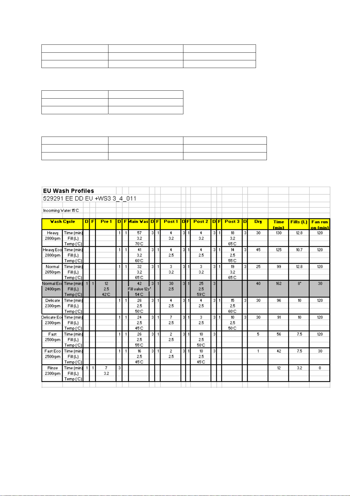
2.2.4 Wash Profiles
2.2.4.1 Europe, Great Britain, Ireland
599735A
13
599735A
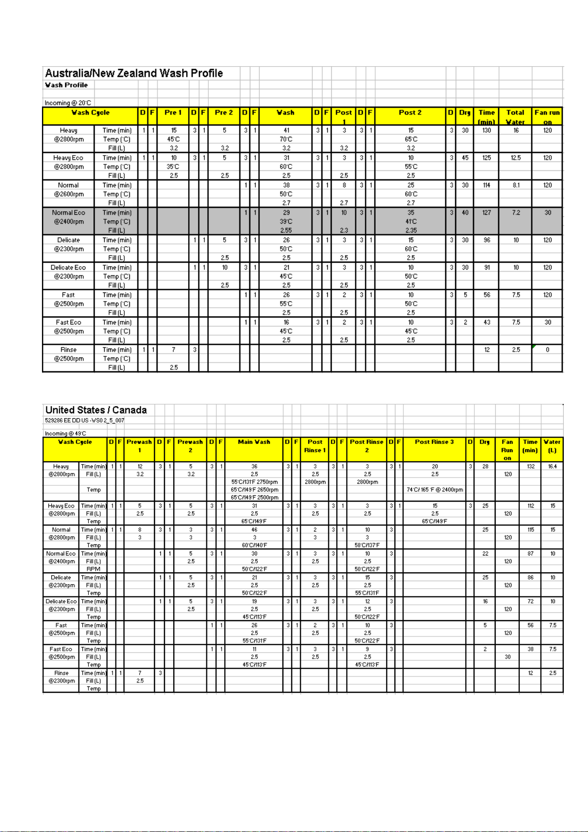
2.2.4.2 Australia, New Zealand
2.2.4.3 Canada, U.S.A.
14

599735A
3 TECHNICAL OVERVIEW
1.1 Chassis
The DishDrawer™ chassis is one complete assembly composed of 5 steel metal components
locked together by a proprietary riveting process. The chassis exterior is made of a lacquered
electro-galvanised material.
Unlike most other dishwashers, the chassis assembly is a load carrying structure designed to
impart stiffness to the product and to ensure deflection is minimised.
The feet of the double cabinet are assembled into the chassis by means of four steel inserts that
are clinched in place to form a permanent threaded connection.
The tub extends 520mm (20
on either side of the tub.
1.2 Drawer Fronts
Prefinished drawer fronts are formed from a painted, brushed or Iridium finish stainless steel blank.
The drawer fronts are attached to the tub by means of formed hooks and two pins that are inserted
through either side of the tub.
On the integrated model, the front panel supplied on each drawer is the mounting panel for the
joinery finished drawer front. The joinery finished drawer front is supplied by the customer.
15
/32”) out of the cabinet by travelling along two rigidly attached slides
3.1 Electronics
In the DD24 / DD60 (Phase 6) electronic controller, the functions of controlling the motor as well as
controlling the user interface console are combined into a single 16-bit micro controller on the main
printed circuit board.
This micro controller also controls a transformerless 85w switch mode power supply. This power
supply utilises a large dropping resistor on the heater plate in conjunction with phase control of the
mains voltage in order to produce a variable voltage supply for the motors, solenoids and drying
fan. From this the controller can supply voltages from 5V to 85V to the various components in the
DishDrawer™.
A separate 24volt dc power supply on the PCB mains filter board (located within the mains filter
housing in the lower left corner of the chassis) supplies power to the microcontroller and LEDs in
the electronic controller.
An isolation relay is mounted on the PCB mains filter and will disconnect power to major
components when signalled to by the controller under certain fault conditions. Once the fault has
been cleared, it will require the power to be disconnected from the product for the isolation relay to
reset.
NOTE: - With power supplies of this nature, all components, regardless of supply voltage,
should be treated as live to earth, i.e. at supply voltage.
The user interface comprises a printed circuit board for front controls and a touch switch panel for
internal controls.
The electronics can connect to a computer service tool via an optical light pen for fault finding and
product information.
The element is switched by one single pole relay. Overheat protection is provided by a thermal
fuse in series with the water heater track on the heater plate. In an over-heat situation, this gravity
fuse drops off and disconnects the water heater element from the supply voltage.
A non-serviceable fuse is mounted within the controller to provide additional safety protection.
15

599735A
3.1.1 Tub Home Sensor
The tub home sensor determines when the tub is closed. The tub home sensor consists of an
infrared sender and receiver mounted on the right side of electronic controller. When the tub is
fully closed, infrared light is transmitted from the sender through a light pipe on the side of the tub,
through a prism mounted in the chassis trim, then back through the other light pipe to the receiver.
If the tub is not fully closed, the circuit is not complete and the appliance will not operate.
3.1.2 Touch Switches
Two touch switches are used on the secondary control panel. The one on the left is used to select
the required wash cycle and the one on the right is used to turn the ECO option on or off. (ECO
times are not necessarily shorter than non-ECO times, but will use less energy.) They are
capacitive touch switches and are supplied with an analogue signal from the controller that will
change in the presence of an earthed mass (i.e. customer’s finger).
3.2 Motor
The motor is a fully electronically controlled 80V, 60w, 3 phase, 6 pole brushless DC motor,
running on wash at between 2300-2850rpm depending on the cycle selected, and at approximately
4200 rpm on drain.
3.2.1 Rotor
The rotor is a four-pole permanent magnet rotor with a graphite bearing at each end of the vertical
shaft. At the lower end of the rotor shaft is the drain impellor and at the upper end is the wash
impellor.
The rotor can only be placed in one position within the motor housing (refer to Section
fitting instructions).
3.2.2 Spray Arm
The spray arm is shaped for most efficient water flow. The holes are positioned for best
penetration into the wash load, with the water jets angled to ensure the spray arm rotates at the
most efficient speed. The pressure of the water being pumped from the spray arm produces
enough downwards pressure to ensure the spray arm does not lift off the rotor. There is a flap
valve moulded into the top of the spray arm. This lets air escape through the spray arm when the
DishDrawer™ is filling with water.
8.14 for
3.3 Wiring Cover
The wiring cover protects the customer from all electrical components in the motor area
underneath the tub. All electrical components, regardless of voltage, should be treated as live with
respect to earth. It also serves to protect the motor assembly, drain and fill hoses from damage
when opening and closing the drawers. The wiring cover acts as a cosmetic part of the product.
The centre of the cover is made from rubber to prevent the transmission of noise from the motor to
other components.
3.4 Lid System
3.4.1 Lid Operation
The lid is a single piece of polymer plastic with a diaphragm/seal co-injection moulded into it. The
centre of the lid can move relative to the seal. Each side of the lid is clipped into a yoke, which is
in turn connected to a worm drive lid actuator assembly containing a small brushed DC 24 volt
motor.
When the product is first plugged in and switched on at the wall, the lid motors are powered up to
ensure that the lid is fully raised. At the beginning of each wash cycle, both lid motors are powered
up to pull the lid down onto the tub in approximately 2 to 3 seconds. The lid remains down for the
duration of the cycle and is only lifted when the DishDrawer™ beeps to signal the end of the cycle,
or if the customer pauses it to gain access to the tub.
16
599735A
3.4.2 During a Power Failure
If power to the DishDrawer™ fails with the lid down, the tub can still be forced open manually if
access is required. It is very difficult however to close the tub again without raising the lid. The lid
actuators can be wound up manually with the tub fully removed. Failure to raise the lid before
closing the drawer can result in the lid seal being damaged.
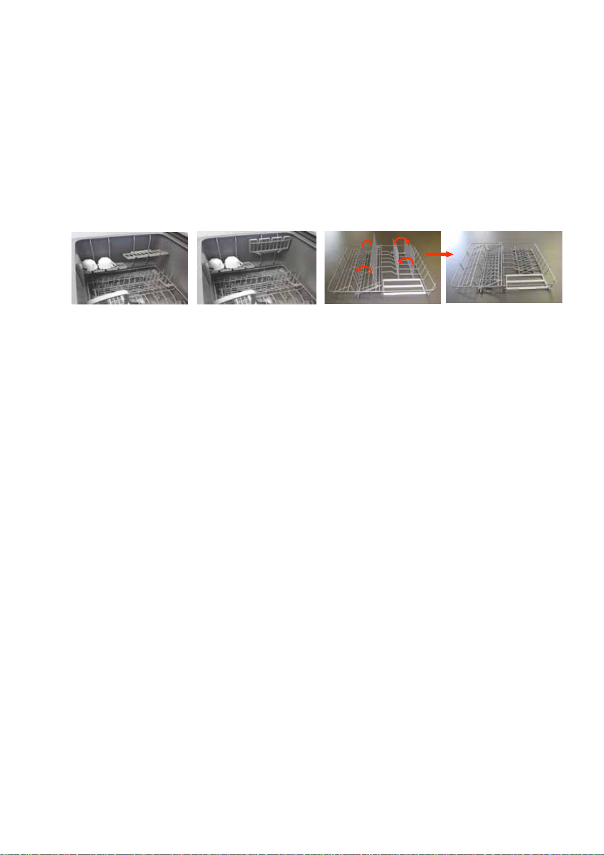
3.5 Tub
The tub is the main cavity where all the wash activity occurs. The tub is a polymer plastic
receptacle that houses the basket ware that includes adjustable cup racks and basket with fold
down tines along with a wash pump and spray arm at the base. The tub also has guide vanes
around its walls which direct falling water from the wash cycle in a clockwise direction around the
filter plate. This clears the filter plate of food particles and washes them into the sump where they
are trapped by the drain filter or pumped out during the drain cycle.
3.6 Filling
3.6.1 Water Inlet
The tub of the DishDrawer™ fills by a single water inlet hose. Hot water connection is
recommended for USA and Japanese products, and a cold water connection recommended for the
Australasian, UK and European products. From the connection to the water supply tap in the
kitchen, the inlet hose enters the cabinet of the dishwasher at the base, onto a dual water valve.
On double models, each tub is supplied water independently via one of the dual valve coils and a
fill hose that runs through a customised link assembly at the back of each tub and travels along the
base of the tub under the wiring cover to the front. At the front of the tub, the fill hose connects to
the water softener (if fitted) then to the detergent dispenser, which directs water into the tub.
Depending on the market and cycle chosen, the product fills through the pre-rinse section of the
dispenser for the pre-rinse cycles and secondly through the main wash section for all other cycles.
In a double product, the controller allows only one inlet valve to operate at a time. This has been
done to reduce EMC emissions. The top tub has priority. This restriction does not apply in
diagnostics mode.
3.6.2 Dispensing Detergent and Rinse-aid
The dispenser is mounted in the front wall of the wash tub.
The detergent dispenser consists of two detergent chambers, one for pre wash and the other for
the main wash.
The detergent dispenser door is opened manually for detergent loading and then manually closed
ready for the detergent to be transported to the wash tub by the inlet water. To enable each
detergent chamber to be dispensed separately, an inlet water diverter valve controlled by the
electronics is required.
Additionally, a positive displacement pump unit and storage tank is incorporated within the
dispenser to supply rinse aid. The rinse aid dispensed volume can be adjusted by the customer in
option adjustment mode. A glowing red light on the tank filler cap indicates an empty rinse aid
tank. The pump frequency is 1 Hz, and makes a slight beeping sound.
17

599735A
3.6.3 Amount of Water
The tub fills with approximately 2.5 litres / 0.8 US gallons of water, almost level with the base of the
spray arm. Once this level is reached, the wash pump (which has load-sensed the fill via the
electronics) becomes primed and pumps the water through the spray arm causing it to rotate. The
load on the wash pump is constantly monitored throughout the wash cycle and the water level
adjusted if necessary. If the wash pump loses prime, the electronics will top up the water level by
opening the fill valve for approximately 5 seconds. It will do this up to 3 times before carrying on
regardless.
3.6.4 Flood Protection
A flood sensor mounted on the side of the mains filter housing provides flood protection. If a flood
is detected, the drain pump will run and an F1 fault code will be signalled to the customer
3.7 Heating
3.7.1 The Heating Element
The heater plate is a porcelain enamelled steel plate with a thick film resistive circuit printed onto
the dry side. A gravity thermal fuse is mounted on the heater plate in series with the heating
element. A large dropping resistor is also printed onto the heater plate which forms part of the
controllers power supply. The element is clamped in place by a locknut and supports the motor at
the base of the tub.
3.7.2 Heating the Water
The heater plate is positioned beneath the filter plate. A flow through water heating system is
created during the wash cycle by allowing water to flow through the filter plate, over the surface of
the element and into the wash pump.
3.7.3 Maintaining the Temperature
A printed circuit board with a temperature sensitive thermistor is mounted on the heater plate.
Sensor components are unserviceable and if they fail a new heater plate is required.
3.7.4 Overheat Protection
The heater plate is only activated during the wash cycles. It is not used for drying. The
temperature is monitored by the thermistor. If a failure occurs with the electronic control of the
heater plate, overheat protection is effected by the thermal fuse on the heater plate.
The thermal fuse consists of a gravity fuse in series with the water heater track that will melt at a
relatively low temperature, 268 –
This fuse does not isolate the dropper resistor and so does not remove power from the controller.
302OC (514 – 576OF) and disconnect the power to the element.
3.8 Motor and Heater Plate Locknuts
There are two locknuts holding the heater plate and motor housing assembly into the base of the
tub to form a watertight seal. They do this by compressing two seals, one between the heater
plate and tub, and the other between the heater plate and the motor assembly.
When reassembling the motor, it is important that a motor shim is placed between the inner locknut
and the inner element seal.
The outer locknut has locations that hold the drain hose, fill hose and wiring loom in place.
Another function of the larger outer locknut is to support and clip the wiring cover.
18
 Loading...