

Fisher & Paykel Dishdrawer DD60SI, Dishdrawer DD60DI Preparation And Installation Manual

Dishdrawer®
Integrated panel preparation
NZ AU GB IE
DD60SI and DD60DI models
Important!
Read these instructions completely and carefully.
Ensure the product is not plugged in.
Installation of DishDrawer® panels requires basic mechanical and electrical skills.
Installation must comply with your local building and electricity regulations.
Failure to install the Dishdrawer® panels correctly could invalidate any warranty or liability
claims.
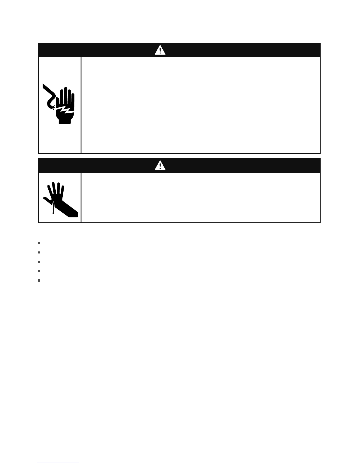
WARNING!
Cut Hazard
Take care - panel edges are sharp.
Failure to use caution could result in injury or cuts.
Safety and warnings
WARNING!
Electrical Shock Hazard
WARNING – To reduce the risk of electric shock, fire, or injury to persons, the
installer must ensure that the DishDrawer® is completely enclosed at the time
of installation.
Before fitting the integrated panel(s) and connecting the integrated badge,
make sure that the DishDrawer® is completely enclosed by cabinetry, and
disconnected from the power supply.
The integrated badge must be electrically connected by a suitably qualified
installer.
Failure to follow these warnings may result in electrical shock, injury or fire.

1
Contents
Double models
Product preparation
2
Single models
Product preparation
4
Panel installation
Badge cut-out, handle, and panel bracket
6
Securing the panel bracket(s)
7
Reconnecting the wires and fitting the
8
panel(s) and a custom toe kick (double models only)
Important!
SAVE THESE INSTRUCTIONS
The models shown in this document may not be available in all markets and are
subject to change at any time. For current details about model and specification
availability in your country, please visit our local website listed on the back cover
or contact your local Fisher & Paykel dealer.
2
(min. 311.5 mm)
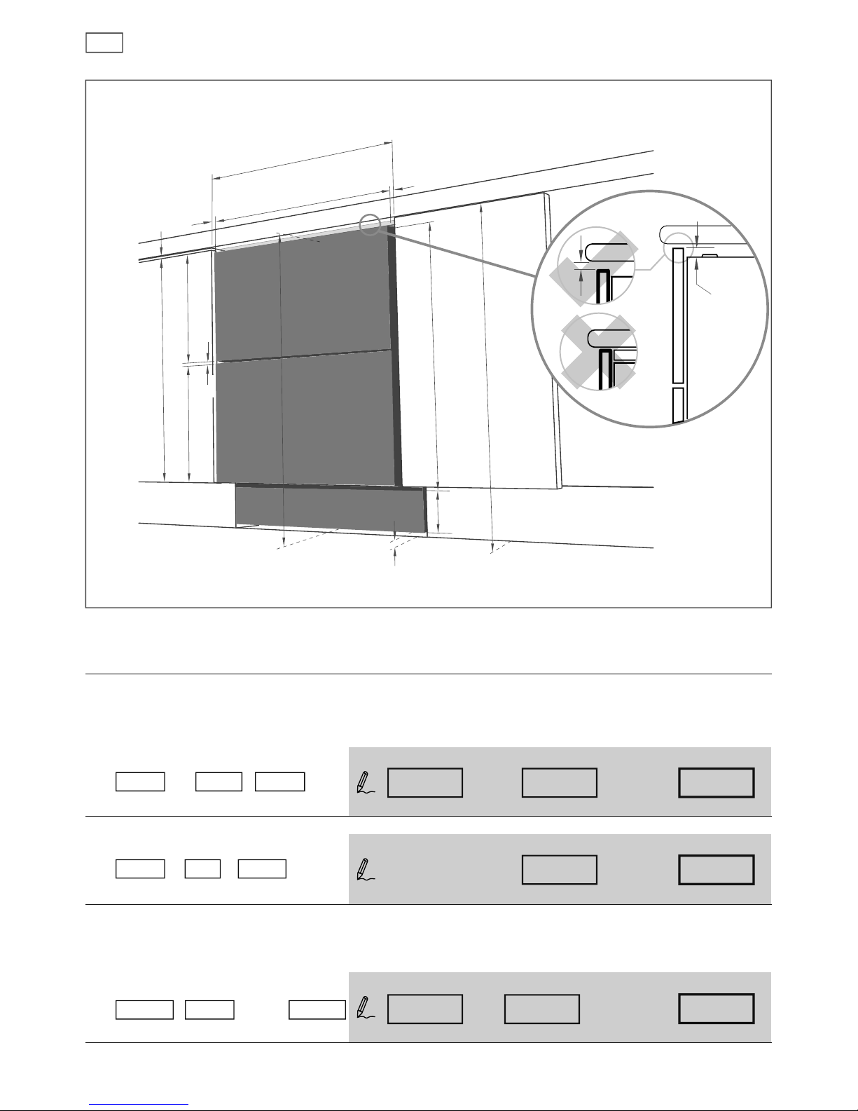
Product preparation
DD60DI models
A
C
Installation diagrams for illustration purposes only
The following calculations assume the top of the upper panel is aligned with the top of the
adjacent cabinetry. The nal panel/cabinetry alignment is achieved by adjusting the feet:
width of ALL panels
Measure
A (
the width between adjacent door/drawer fronts) and write it in the rst box below,
then complete the equation.
eg 600 mm - 2 x 2.5 mm = 595 mm - 2 x =
height of upper panel
eg 398 mm + 0 mm = 398 mm 398 mm + =
height of lower panel
Measure
C (
door/drawer height (or equivalent)) and write it in the rst box below,
then complete the equation.
eg 717.5 mm - 398 mm - 8 mm = 311.5 mm - - 8 mm =
Note: The ‘door extension’ B allows for the top of the upper panel to be above the DishDrawer® where required.
min. 2.5 mm
width of ALL panels
min. 2.5 mm
min. 2 mm
min.
2 mm
upper
panel
height of
upper panel
A
door clearance panel width
A
width ALL panelsdoor clearance
(min. 595 mm)(min. 2.5 mm)
Air gap
lower
panel
toe kick panel
B
height of
lower panel
819.5 - 879.5 mm
735 mm
D
height of
toe kick
panel
8 mm
Air gap
B
height
upper panel
standard height
B door extension
(0 mm recommended)
C
height
upper panel
height
lower panel
C
(min. 717.5 mm + B)
height upper panel
Air gap
height lower panel
height upper panel
min.
12 mm
 Loading...