

Fisher & Paykel DishDrawer DD605 Prefinished LCD, DishDrawer DD605 Integrated, DishDrawer DD605 Prefinished Flat Door Installation Instructions Manual
Important!
SAVE THESEINSTRUCTIONS
The models shown in this documen_ moy not be _vaildble in all markets and are subject to _hange a_ any time. For _urren_ details about model and specification availability in your _ountry, please go to our website www.
_sherpaykel.com or _onta_ t your lo_ al Fisher& Paykel dealer.
SAFETY AND WARNINGS
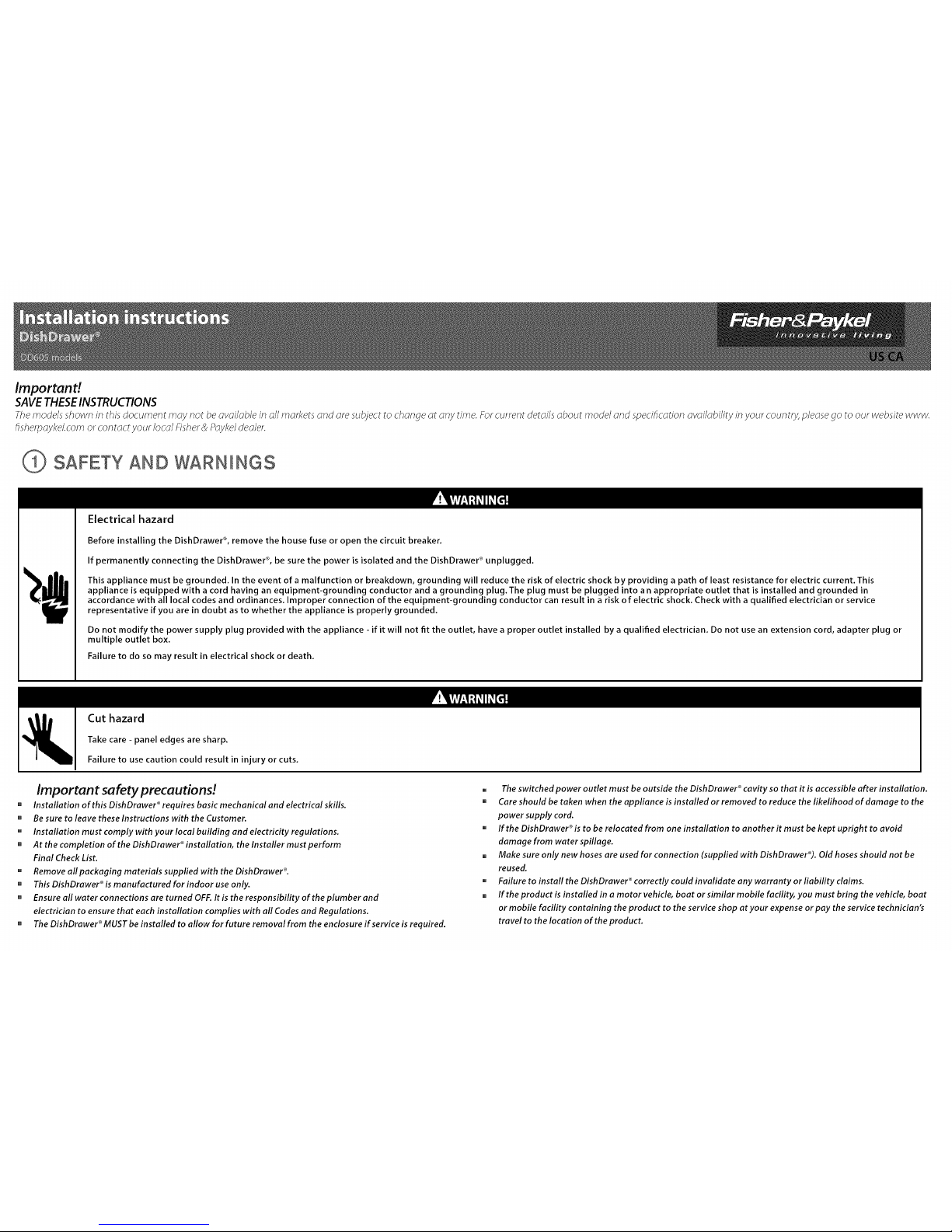
Electrical hazard
Before installing the DishDrawer ®,remove the house fuse or open the circuit breaker.
If permanently connecting the DishDrawer ®,be sure the power is isolated and the DishDrawer ® unplugged.
This appliance must be grounded. In the event of a malfunction or breakdown, grounding will reduce the risk of electric shock by providing a path of least resistance for electric current. This
appliance is equipped with a cord having an equipment-grounding conductor and a grounding plug.The plug must be plugged into an appropriate outlet that is installed and grounded in
accordance with all local codes and ordinances. Improper connection of the equipment-grounding conductor can result in a risk o f electric shock. Check with a qualified electrician or service
representative if you are in doubt as to whether the appliance is properly grounded.
Do not modify the power supply plug provided with the appliance - if it will not fit the outlet, have a proper outlet installed by a qualified electrician. Do not use an extension cord, adapter plug or
multiple outlet box.
Failure to do so may result in electrical shock or death.
Cut hazard
Take care - panel edges are sharp.
Failure to use caution could result in injury or cuts.
Important safety precautions!
[] Installation of this DishDrawer ®requires basic mechanical and electrical skills.
[] Be sure to leave these Instructions with the Customer.
u Installation must comply with your local building and electricity regulations.
[] At the completion of the DishDrower ®installation, the Installer must perform
Final Check List.
u Remove all packaging materials suppfied with the DishDrawer ®.
[] This DishDrawer ®is manufactured for indoor use only.
[] Ensure all water connections are turned OFF.It is the responsibility of the plumber and
electrician to ensure that each installation complies with all Codes and Regulations.
[] The DishDrawer ®MUST be installed to allow for future removal from the enclosure if service is required.
u The switched power outlet must be outside the DishDrawer ®cavity so that it is accessible after installation.
[] Care should be taken when the appliance is installed or removed to reduce the likelihood of damage to the
power supply cord.
u If the DishDrawer ®is to be relocated from one installation to another it must be kept upright to avoid
damage from water spillage.
[] Make sure only new hoses are used for connection (supplied with DishDrawer®). Old hoses should not be
reused.
u Failure to install the DishDrawer ®correctly could invalidate any warranty or liability claims.
[] If the product is installed in a motor vehicle, boat or similar mobile facility, you must bring the vehicle, boat
or mobile facility containing the product to the service shop at your expense or pay the service technician's
travel to th e location of the product.
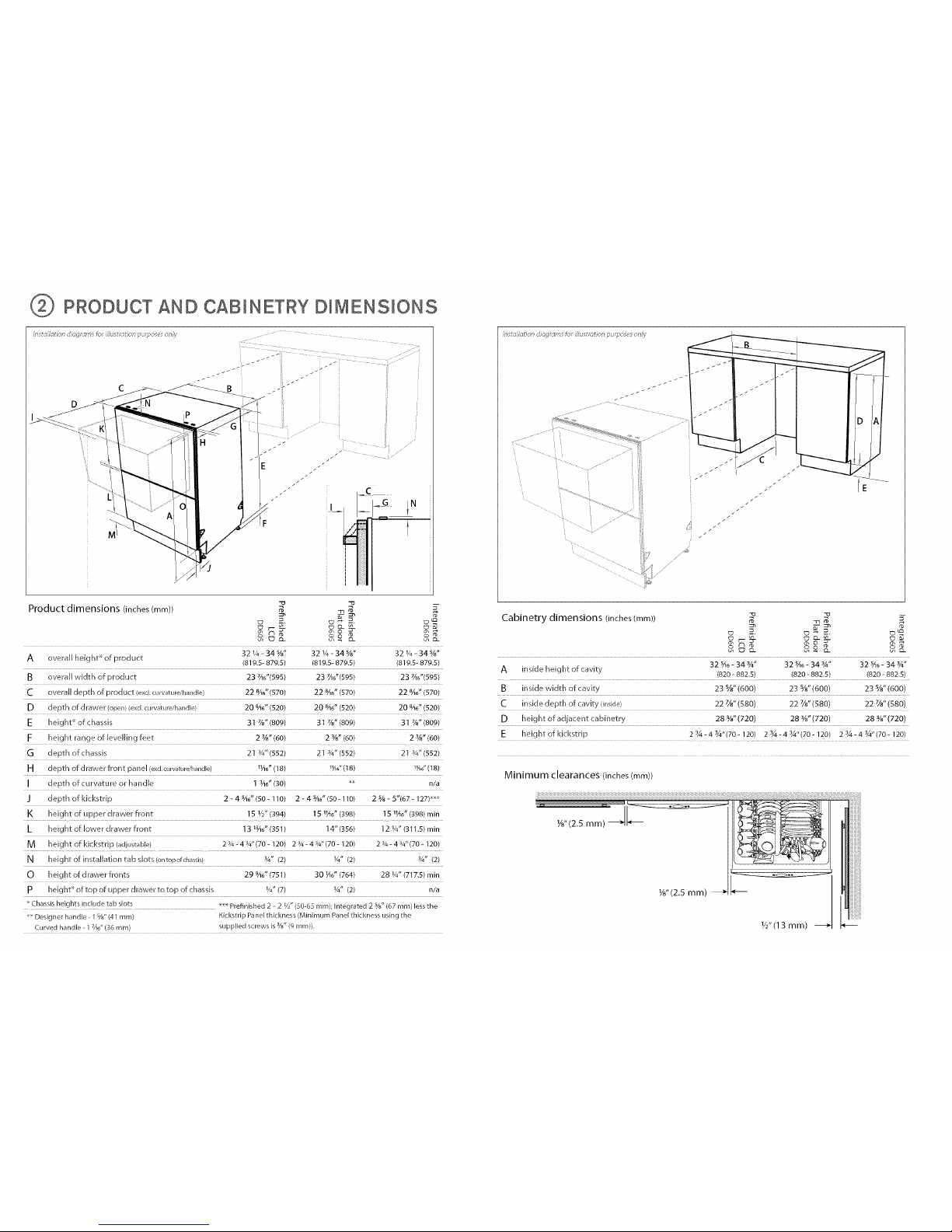
PRODUCT AND CABINETRY DIMENSIONS
/?sta/lat on <iiag!ar, sro_ i//u£!atio ! pu@oses o ?,_y
Product dimensions (inches (mm)) _ -a _ 5"
32¼-34%" 32 ¼-34%" 32¼-34%"
A overall height_ of product (819.5-879.5) (819.5-879.5) (819.5-879.5)
B overall width of product 23 %6"(595) 23 7A6"(595) 23 7A6"(595)
C overall depth of product (exd.curvature/harldle) 22 8A6"(570) 22 846"(570) 22 8A6"(570)
D depth of drawer (open}(exd (Llrvature/har/dle} 20 8A6"(520) 20 8A6"(520) 20 8A6"(520)
E heigh¢of chassis 31 7/8"(809) 31%"(809) 31 7/a"(809)
F height range of [eveihng feet 2 3/8"(60) 2 %" (60) 2 ¥8" (60)
O depth ofchassis 21%"(552) 21%"(552) 21%"(552)
H depth of drawer front pa rrel (exc[curvature/handle) _1A6"(18) "A_"(18) "A6"(t 8)
I depth of curvature or handle 1sac"(30) _ n/a
J depthofkickstrip 2 - 4 SA6"(50-110) 2 - 4 SA6"(50-110) 2 %- 5"(67-127) _
K height of upper drawer front 15 1/2"(394) 15 hA6" (398) 15 1¼o"(398) min
L height of lower drawer front 13 t3A6"(351) 14" (356) ] 2 1A"(311.5) min
M height of kickstrip (adjustable) 2 %- 4 %"(70-120) 2 %- 4 %"(70-120) 2 %- 4 %"(70-120)
N height of insta%tion tab slots (ontopofchassis) 3_,, (2) Y4" (2) ¾" (2)
0 height of drawer fronts 29 9A6"(751) 30 H6" (764) 28 ¼" (717.5) rain
p height_ of top of upper drawer to top of drassis ¼"(7) _/4" (2) n/a
......Chassisheights include tab slots _ Prefinished 2 _2 /2"(50 6:_mm}; Integrated 2 5_/8,,(67 ram) lessthe
Designer handle 1%" (41 ram) Kickstrip Panel thickness (Minimum Panelthickness using the
7 3
Curved handle 1 Ze" (36ram) supplied screws is Y_"(9 ram)).
///
//
Cabinetry dimensions (inches (ram)) =_ ---n_ _5-
c_ -=. c_- =. c_
w
32 SA_- 34 %" 32 SAo_34 %" 32 SA_- 34 %"
A inside height of cavity (820 - 882.5) (820 -882.5) (820 -882.5)
B inside width of cavity 23 %" (600) 23 %" (600) 23 %" (600)
C inside depth of cavity (inside) 22 7/8,,(580) 22 7/8"(580) 22 7/8"(580)
D height of adjacent cabinetry 283/W' (720) 28 _/_"(720) 28 _/W'(720)
E heightof kickstrip 23A-43A"(70-120) 23A-43_"(70-120) 23_-43A"(70-120)
Minimum clearances (inches(mm))
W'(13 mm) -_
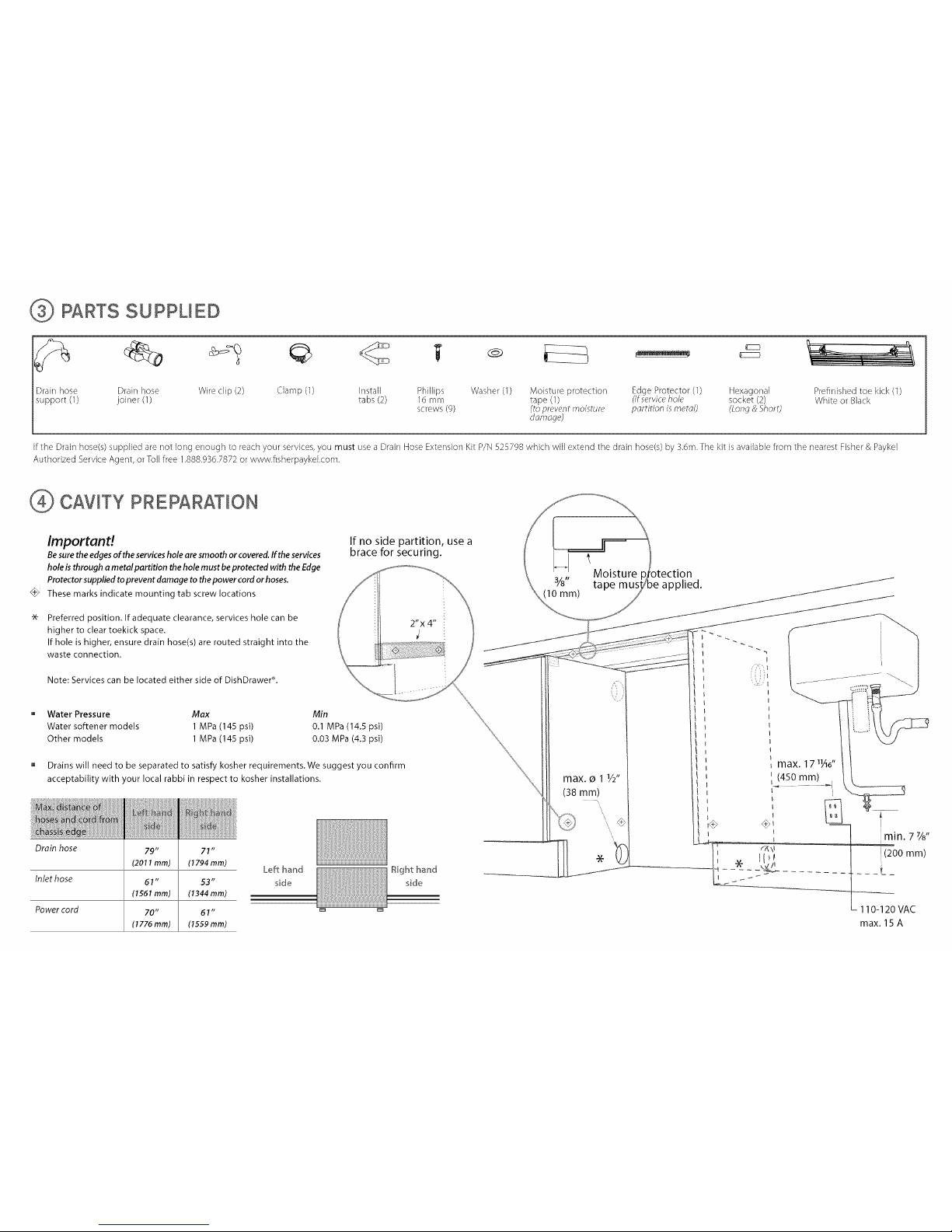
PARTS SUPPUED
Drain hose Drain hose Wire clip (2) Clamp (3) Install Phillips Washer (3) Moisture protection Edge Protector (1) Hexagonal
support (1) joiner (1) tabs (2) 16 mm tape (1) (ifservice hole socket (2)
screws (g) (to prevent moisture pordtion isr'netol) (Long & Short)
dorn_ge)
Prefinished toe kick (1)
White or Black
If the Drain hose(s) supplied are not long enough to reach your services, you must use a Drain Hose Extension Kit P/N 525798 which will extend the drain hose(s) by 3.6m. The kit is available from the nearest Fisher & Paykel
Authorized Service Agent, or Toll free 1.888.936.7872 or www.flsherpaykekcom.
CAVITY PREPARATION
Importand
Besure the edges of the services hole are smooth or covered. If the services
hole is through a metal partition the hole must be protected with the Edge
Protector supplied to prevent damage to the power cord or hoses.
_F These marks indicate mounting tab screw locations
Preferred position. If adequate clearance, services hole can be
higher to clear toekick space.
If hole is higher, ensure drain hose(s) are routed straight into the
waste connection.
Note: Services can be located either side of DishDrawePL
If no side partition, use a
brace for securing.
u Water Pressure Max Min
Water softener models 1 MPa (145 psi) 0.1 MPa (14.5 psi)
Other models 1 MPa (145 psi) 0.03 MPa (4.3 psi)
[] Drains will need to be separated to satisfy kosher requirements. We suggest you confirm
acceptability with your local rabbi in respect to kosher installations.
Drain hose
Inlet hose
Power cord
79"
(2011mm)
61"
(1551mm)
70"
(1776mm)
71"
(1794 ram)
53"
(1344 mm)
61"
(1559 ram)
Left hand
side
Right hand
sale
Moisture
3/8" applied.
(10mm)
max. _ 1 V2"
(38 ram)
,
',
\
max. 17_¼6"
(4.50 ram)
min. 7%"
[(200 ram)
- 110-120 VAC
max. 15 A
 Loading...