

Fisher & Paykel DD605BK-88464A, DD605FD-88468A, DD605HSS-88466A, DD605I-88469A, DD605IH-88470A Installation Guide
...Page 1

Installation instructions
DD605 and DS605 model
OishDl a _e_
Page 2

Safety and warnings
Electrical hazard
Before installing the DishDrawer ®, remove the house fuse or open the circuit
breaker.
if permanently connecting the D[shDrawer% be sure the power is isolated
and the DishDraweF _unplugged.
Failure to do so may result in eJectrica[ shock or death
Take care ,_pane[ edges are sharp.
Cut Hazard
Failure to use caution could result in injury or cuts.
InstaHution of this DishDrawer _ requires basic mechanical and dectrical skills.
Be sure to Jeave these instructions with the Customer.
Installation must comply with your !ocal buiMing and electridty regulations.
At the c_m_Ieffon of the DishDrawer_ inst_ation_ @e inst_ffer must perform Fin_l Check LisL
Remove aH packaging materials suppfi'ed with the DishDrawerX
This dishwasher is manufactured for indoor use only.
Ensure aH water connections are turned OFF. it is the responsibility of g_e plumber and
dectridan to ensure that each installation complies with aft Codes and Regtdations.
The DishDrawer _ MUST be instaNed to allow for future removal from the enclosure if service is
required.
The sv_itched p_wer _u_et must be _utside the DishDrawer® c_vity s_ that it is accessibfe after
instaHaffon.
Care should be taken when the appfiance is installed or removed to reduce the likeflhood of
damage to the power supply cord.
if the DishDrawer _"is to be rdocated &am one instafiafion to another it must be kept uproht to
avoM damage &om water spiflage.
Make sure on_y new hoses ore used for connection (suppfled with DishDrawerO. Old hoses
should not be reused.
Failure to install the DishDrawer correctly could invalidate any warranty or liability claims.
Page 3
DOUBLIE/VIODIE/,,,,S
PIl°oductalsd calbilset_°ydimensions
Installation
Cavity ip_epal_atio_
Route rise Ihosesand move i_sto rise cavity
Removit_g rise tub alsd leveIH_"_gthe pll°oduct
Secur@3gthe iplL°oductand refitting the b4b
Plumbilr_ 9 and drainage - OIPTION I
Plumbing alnd @ailr_age OPTION 1(connection
Plumbing and @ahsage OPTION 2
Plumbing and @ailnage - OPTION 2 (connection
Fitting _he _oekick
SINGI,,,,IEMODH,,,,,S
Piioduct alrsdcabine_'y dimelrssions
Installation
Route the Ibosesand move hr_tothe cavity
Removhsg the tub and secudln9 the product
ReFitting the Iub
PIumbilr_9 and drainage - OPTION I
Plumbing and drainage --OPTION 1(connection
Phmbing and @ainage OPTION 2
Phmbhsg and @ailnage OPTION :;t(connection
4
5
5
7
8
9
10
11
12
14
16
17
18
19
20
21
22
23
Final checklist
Importand
SAVETHESEINSTRUCTIONS
The models shown in this User Guide moy not beavoilobl_ _in oll mork_>t__nd ore
subject to chonge ot ony time. For currant d_>toi/_obout model _nd specifk:ofion
owi/obi/ity in your country, p/_)asego to our w_bsite www.fisherpoyk_/.com or
contodt your bccTIFisher & PoyMI d_a/_<
24
Page 4

Product dimensions
/ S ,iii i'f !i !:)!//_, ,i i )_!_, :)
Product dimensions
(mm)
A overallheight* of pFocJ_c_ 819.5 - 879.5 819.5- 879.5 819.5 - 879.5
B ove_a Iwclth of: p_oduct 595 595 595
C overall cleplh of D_oduct e×cl curw¢ ire/harMle) 570 570 570
D depth of @awe (operO(e×c[.curvatu_'e/_andle) 520 520 520
E height of d_assis 809 809 809
F heght _al_ge of levelling feet 60 60 60
G del:)tl'l of c__assis 552 552 552
H depth of draweL, front panel (exc[curvatireli_nd[e) 18 18 18
I depth of c/ vatu_e o_ har_dle 30 _"_ n/a
J depth of k ( kstr p 50 - 65 50 - 65 67 - 127'_
K t_eigb.t of upDel (_ ,_wel f_ont 394 398 398 min
L heightoflowe_cbawerfront 312.5 311.5 311.5 min
M heght o k ckstrip (adjust_ble) 70-120 70-120 70-120
N heigh_ of r_sta[ a_io__tab slots (on topof cha'_si) 2 2 2
0 _eight o_@awel flonts 719.5 717.5 717.5 min
P Iegh'_of l:op of upper d_awe_ to top of chas?, s 7 2 n/a
Chassis height'_ include tab slots Pref:lni bed 5065 mm [ntegra ed 07 mm le the Kickstrip
.............................................................................................................. Paise[ thickness (Minimum Panel thickness using _he supplied
DesigneH]andle 41ram Curved handle 3dram so_,wsisgmm).
Page 5
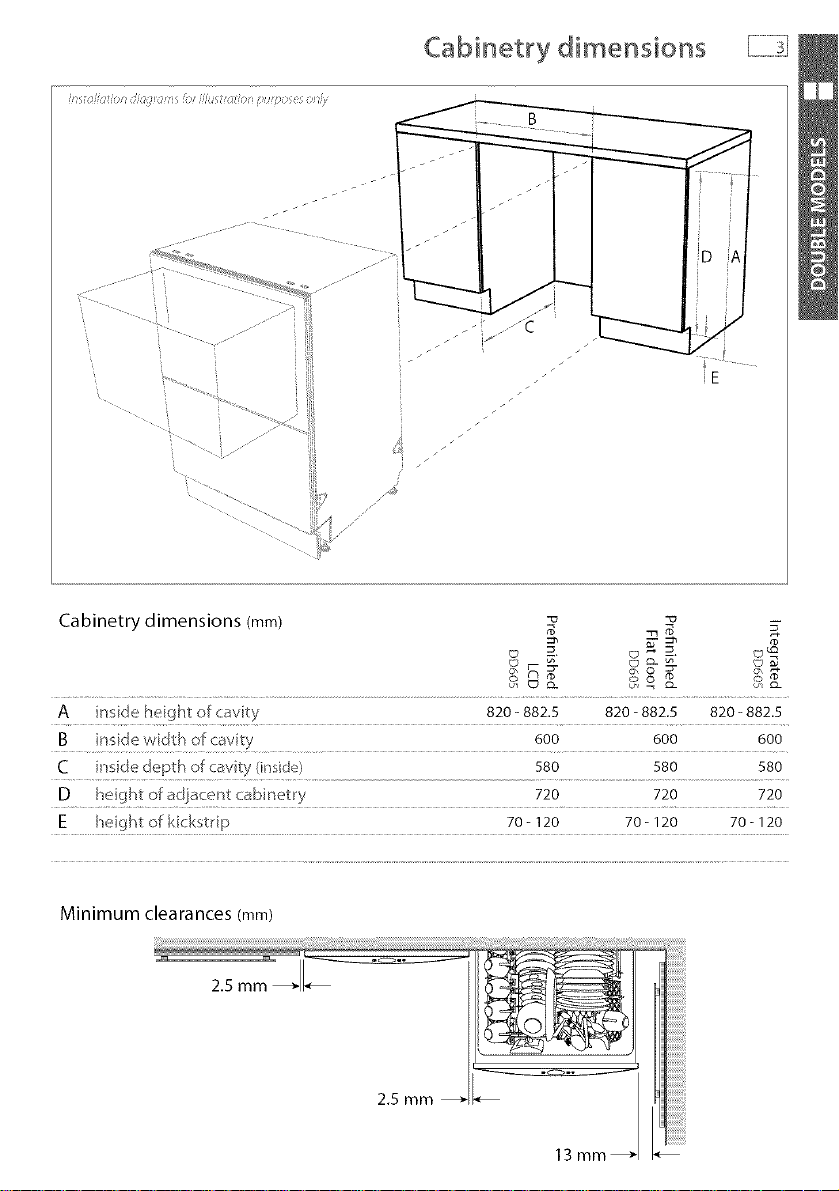
Cabinetry dimensions
?",,,, ......
f
/y"
iiiiiiiiii?iiiiiiii?iiiiiiiiiiiiiiiiiiiiiiiii
Cabinetry dimensions (ram) _ "_
A in_:,_e hegh_ of o_vty 820- 882.5 820- 882.5 820- 882.5
B 600 600 600
C r_de depth o_ cavity (in id_) 580 580 580
D 720 720 720
E heigh_of kick_,t_ ip 70 - 120 70 - 120 70 - 120
Minimum clearances (ram)
13mm _ _.
Page 6
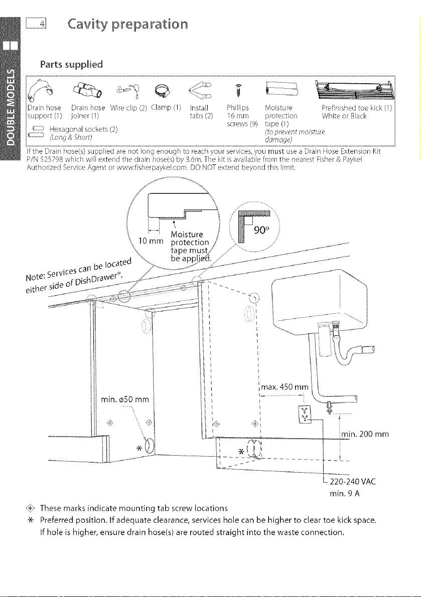
Cavity pt_epa_ation
Parts supplied
Drain hose Wireclip (2) Clamp (1) Install
Ifthe Drain hose(s)supplied arenot long enough to reachyour services,you must usea Drain HoseExtension Kit
P/N525798which will extendthe drain hose(s)by 3.dm.The kit isavailablefrom the nearestFisher& Paykel
Authorized ServiceAgent or www.fisherpaykeLcom. DONOTextend beyond this limit.
tabs (2)
Phillips Moisture
16 mm protection
screws (% tape (1)
ddmdge)
14 o,sture
10mm protection
ote Services can be located
_ithe'r side of DishDr_
_max. 450 mm
min. o50 mm
....I_ '..... _ _n. 2OOmm
_E_0--?40vAc
rain. 9 A
@ These marks indicate mounting tab screw locations
-_ Preferred position. If adequate clearance, services hole can be higher to clear toe kick space.
If hole is higher, ensure drain hose(s) are routed straight into the waste connection.
Page 7

Route the hoses and move into the cavity
i ....................I/iSIIII]IIIIII]
/............iiiiiiii.............i
i i i
"_'Tetogether to avoid kinking
ii
Ii
ii
Ii
.............................. If top two tabs are being
s. _) used, ensure they're securely
_ _'. _" fitted before sliding product
/ into cavity.
Loosen feet first, but /
do not fully extend
until product is in cavity.
optional
Ensure hoses and cord
are not kinked or twisted.
Page 8
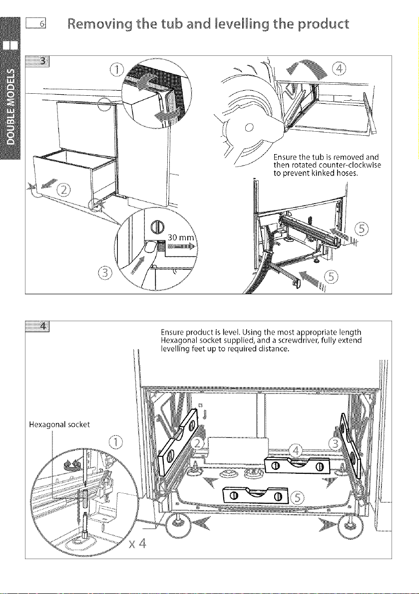
_] Removin9 the tub and _eveHin9 the product
Ensure the tub is removed and
then rotated counter-clockwise
to prevent kinked hoses.
Hexagonalsocket
Ensure product is level. Using the most appropriate length
Hexagonal socket supplied, and a screwdriver, fully extend
levelling feet up to required distance.
×4
Page 9

Secudn9 the product and refitting the tub
The mounting tabs
arein pairs,one on
each sideof the
product. At least two
setsof tab pairs must
be used.
A and B tab pairs
ORB and Ctab pairs
or all three pairs.
Ensurethe sound i
insulation is
repositioned
correctly.
Ensure the tub is
now rotated
clockwise back.
Ensure the tub clips on
both sides are reset.
Before refitting the tub,
ensure the hoses are not
twisted and the latches at
the rear of each drawer
runner are facing forward.
Page 10

Humbing and drainage -OPTmON 1
DishDrawer ®and Standpipe O38 mm
min. R200 mm
Drain hose 2011 mm 1794 mm
Inlet hose 1561 mm 1344 mm
Powercord 1776 mm 1559 mm
Water Pressure Max Min
Water softener models 1 MPa (145 psi) 0.1 MPa (14.5 psi)
Other models 1 MPa (145 psi) 0.03 MPa (4.3 psi)
Drains will need to be separated to satisfy Kosher requirements. We suggest you confirm
acceptability with your local Rabbi in respect to Kosher installations.
Page 11

Humbing and drainage - OPTION 1 (connection
DishDrawer ®and Standpipe _38 mm
............................If space is limited
..................................... height
for fixing, push hose --
through drain hose
.......... support to required
...................................... ,,,,,,%
"%
Page 12

P_umbing and drainage - OPTmON2
DishDrawer ®using sink trap with drain hose joiner
E
min. R200 mm
Page 13

Humbing and drainage : OPTION 2 (connection
DishDrawer ®using sink trap with drain hosejoiner
Ifspace is limited
............................. for fixing, push hose
................ _ support to requir
43.
..... through drain hose
height
: f
Z50-
i882.5
imm
sarerout :,_
omer. Rempv_
material if_
%
Page 14

_i] Fittin9 the toekick
Important!
Do not overtighten screw,
Page 15

Page 16

Product dimensions
C °_ B
Product dimensions (mm) _
F _K
A overall height o[pr(duct 409 409 409
B overa Iwidth of p_oduct 595 595 595
C overall depth of product (ex[ curvature/handlu) 570 570 570xx
D dept] of drawe_ (open) (excl curvat lie/handle) 520 520 520
E heght _ o[ chassis 409 409 409
F depfl_ o[ chass s 552 552 552
O depl[" of @awer hont panel (exd curva ure/h ndle) 18 18 18
H depth of _/ vatule o_ bar,die 30 _"_ n/a
I height of dawe[ fon_: 394 398 398 min
J hegh_ of wmtng area a_base of p_oducl 7 9 9
K height of nstaHation tab slots (ontopof cha si ) 2 2 2
L height of top of d_avve_to top of chassis 7 2 n/a
Chassis heigi]ts inc[ ide tab slots Panel t[fid<ness 18 mm Designer hal_d[e 41 ram, Cul'ved harldle- 36 him
No[e: for PL'e/inished Flat door models, the heigh[ f_on] the top of handle _o the top of door 595mm
Page 17

Cabinet y dimensions
i! :Iii_Fio_ <1;,'<t<;,' 5/<:t //( FIiFP,f ,,: tp s ,<:!_2
i
I
Cabinetry dimensions (mm) _ -_
A 412 412 412
B 600 600 600
C insde depth of cav _)' (inqde} 580 580 580
D c ealal_ce below benc _top Minimum 3 _ Minimum 3 _ Minimum 32
Clearai_ce is measured from ............................................................................................................
Minimum clearances (mm)
13mm _
Page 18

Cavity preparation
Cavity
Ifthe Drain hose(s)supplied arenot Eongenough to reachyour services,you must use aDrain HoseExtension Kit
P/N525798which will extendthe drain hose(s)by 3.6m.The kit is availablefrom the nearestFisher& Paykel
Authorized ServiceAgent or www.fisherpaykelcom. DO NOTextend beyond this limit.
t
10 mm protection
• "ces can be located
Note. SerVl _nishDrawer <_.
either side oF
Moisture
.s E............ z_ -J
I
max. 450 mm
t
[ min. 200 mm
',, 1[Importantl min.4.5A
I I /,extendabovecavitybase
These marks indicate mounting tab screw locations
Note: To align drawer front to adjacent cabinetry, the product to counter top clearance can be
increased to 3 mm.
Preferred position. If adequate clearance, services hole can be higher.
If hole is higher, ensure drain hose(s) are routed straight into the waste connection.
Adjacentc_binetrymustnot
Page 19

Route the hoses and move into the cavity
Tie together to avoid kinking
Ensure hosesand cord
are not kinked ortwisted.
Page 20

Et Removin9 the tub and securin9 the product
©
Ensure the tub is removed and
then rotated counter-clockwise
to prevent kinked hoses.
The mounting tabs are in
pairs, one on each side of
the product.
Ensure the sound insulation
is repositioned correctly.
Page 21

+! Ensure the tub clips on
! 1_:_, both sides are reset.
ku: _ }
Ensure the tub is
now rotated "g_
clockwise back.
Refittin9 the tub
_,' " ..... ,111111%
Before refitting the tub,
ensure the hoses are not
twisted and the latches at
the rear of each drawer
runner are facing forward.
Page 22

Humbing and drainage -OPTmON 1
DishDrawer ®and Standpipe O38 mm
cO
Drain hose 2011 mm 1794 mm
Inlet hose 1561 mm 1344 mm
Powercord 1776 mm 155g mm
Water Pressure Max N/in
Water softener models 1 MPa (145 psi) 0.1 MPa (14.5 psi)
Other models 1 MPa (145 psi) 0.03 MPa (4.3 psi)
Page 23

Humbing and drainage : OPTION 1 (connection
DishDrawer ®and Standpipe _38 mm
If spaceis limited
for fixing, push hose --
through drain hose
support to required
ii i ii
iii
Page 24

Humbin9 and drainage -OPTmON 2
DishDrawer ®using sink trap with drain hosejoiner
Lfb
_q
cO
cO
>
HIGHLOOP
min. 150 mm
Page 25

Humbing and drainage - OPTION 2 (connection
DishDrawer ®using sink trap with drain hosejoiner
............. If space is limited
................ for fixing, push
.................................. support to requi
JJ
/,
through drain hose
.....h#ight
..................
Page 26

Final checklist
Check all parts are installed.
Ensure product is level, securely fastened to the cabinetry and opens and closes freely. The
DishDrawer ®must be free to fully close with no resistance from the cabinetry.
Ensure inlet hose to water supply has rubber washer fitted and is tightened a further half turn
after seal contact.
Ensure any knockouts or plugs in drain connection have been drilled out and drain connection
has been made.
The drain hose connector must not support the weight of excess hoses. Keep hoses asfully
extended as possible to prevent sagging. Any excess length of hose should be kept on the
dishwasher side of the high loop.
If using Plumbing and Drainage OPTION 2, ensure the Highloop is a minimum 150 mm
higher than the drain hose connector.
Turn on the power and water supply. Then press the power button to turn the DishDrawer ®on.
The DishDrawer ®should beep and cycle select lights light up.
Check the sprayarm(s) are in place and free to rotate.
Add three cups of water into the DishDrawer ®.
On the Wash Programme Selector Panel press Rinse
and close the drawer(s). Start the programme by pressing
the Start/Pause button.
After the Rinse programme has finished, ensure machine has run and drained correctly.
Check water supply and drainage connection for leakage.
Repeat for each Drawer.
Troubleshooting
Excessive water remaining above the filter pJate, after the rinse cycle
Check for kinked drain hoses or blocked waste connection, high loop not properly installed or
drain hoses not routed correctly.
No water supply (_ shows on display)
Check water is connected, turned on and the spray arm(s) is correctly fitted and free to rotate.
DishDrawer '_does not _ight up when the tub is opened
Ensure power is connected and is switched on. Check if Auto Power option is on.
Water around water supply and drainage connections
Check connections, existing plumbing and hoses for leaks. Check washer and hose clamps are
correctly fitted.
If product is tipping
Ensure the product is secured to the cabinetry. Refer to page 7 or 18.
If front panels are misaligned
Check and relevel product. Check the cabinetry is square.
Drawer(s) don't close properly
Ensure nothing is obstructing the drawer(s) from closing properly ie sound insulation, hoses or
tub latches.
If a problem occurs, consult the Troubleshooting section of the User Guide.
If after checking these points you still need assistance, please refer to the Service & Warranty
book for warranty details and your nearest Authorized Service Centre, or contact us through our
website, www.fisherpaykel.co m.
Page 27

Co syr/gnr o k sher & Pay tel 2007. AI £_[s _eservea
eCLiLCa_lor',sn mls DO©K(_LdbE
l//8 JOOC('tS c](_ r XJttels tie RDOQ a[ IN6
_)l >su(t UHU('I )[G(3[]YIIISOU _ ) )(b,:/_
l_1"1@ YOU IU LI/U ©[©/@ t[ _CK WIll VOU W(-d( [C
x _ [Ih/ IOOOKIO]" CO rOC{ (5('btItIJeb ll]©
" i_[ Q_l]{ avails r
[I]OSI s SIz_ _ L-_Jk u_ J_ H a Br3 f1(_[ _ ST
wwwoi_ishe_paykel°¢om
_ZAU GB tE
DishDrawer inslallatior- instructions
Pu_l_shed: 06/2007
Pa_t No° 529322 A
 Loading...